Loading ...
Loading ...
Loading ...
4° _R HEAD _ F_ures 8 _ 9
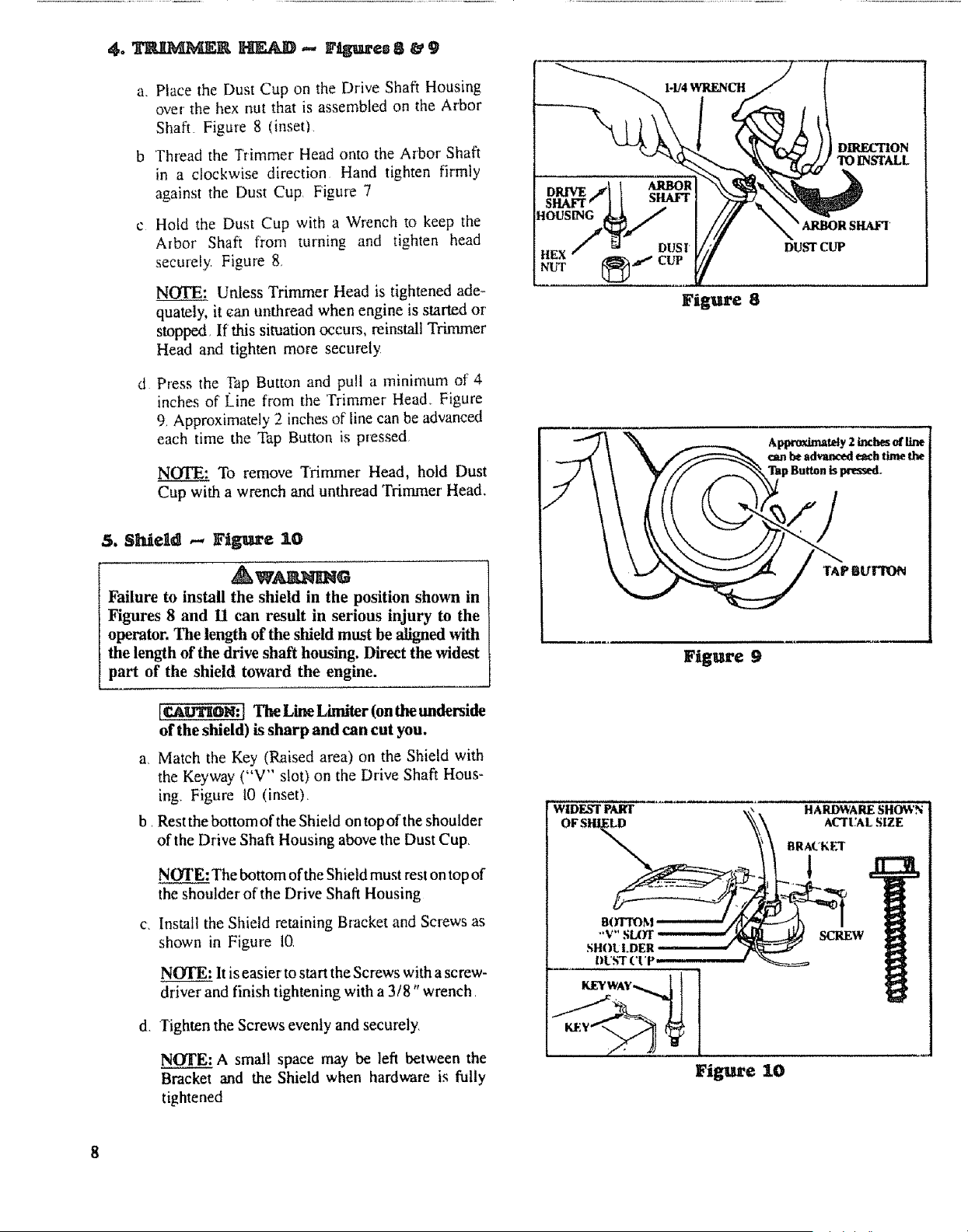
a_ Place the Dust Cup on the Drive Shaft Housing
over the hex nut that is assembled on the Arbor
Shaft. Figure 8 (inset)
b Thread the Trimmer Head onto the Arbor Shaft
in a clockwise direction Hand tighten firmly
against the Dust Cup Figure 7
d
Hold the Dust Cup with a Wrench to keep the
Arbor' Shaft from turning and tighten head
securely Figure 8
NOTE: Unless Trimmer' Head is tightened ade-
quately, it can unthread when engine is started or
stopped If this situation occms, reinstall Trimmer
Head and tighten more securely
Press the Pap Button and pull a mininmm of 4
inches of Line from the Trimmer Head+ Figure
9_ Approximately 2 inches of line can be advanced
each time the Tap Button is pressed
NOTE______S+:To remove Trimmer Head, hold Dust
Cup with a wrench and unthread Trimmer Head.
5. $Meld ,-, Fllgure 10
.Aw_G
Failure to install the shield in the position shown in
Figures 8 and I1 can result in serious injury to the
operator. The length of the shield must be aligned with
the length of the drive shaft housing. Direct the widest
part of the shield toward the engine.
[CA_ON: l The Line Limiter (on the underside
of the shield) is sharp and can cut you.
a Match the Key (Raised area) on the Shield with
the Keyway ("V" slot) on the Drive Shaft Hous-
ing Figure 10 (inset)
b Rest the bottom of the Shield on top of the shoulder
of the Drive Shaft Housing above the Dust Cup,
d,
NOTE: The bottom of the Shield must rest on top of
the shoulder' of'the Drive Shaft Housing
Install the Shield retaining Bracket and Screws as
shown in Figure 10
NOI'E: It is easier to start the Screws with a screw-
driver and finish tightening with a 3/8" wrench
Tighten the Screws evenly and securely.
NOTE: A small space may be left between the
Bracket and the Shield when hardware is fully
tightened
DRIVE ARBOR
SHAVFf SHAFT
Figure 8
Approxim_y 2 inches of line
_TAP BtYlTON
Figure 9
WIDEST PART HARDWARE SHOWN :
OF SHIELD ACTUAL SIZE
sun" scow
SHOt LDER ..... +" "
I)US'T ('I'P.
KEYWA¥_ 1t
Figure 10
Loading ...
Loading ...
Loading ...