Loading ...
Loading ...
Loading ...
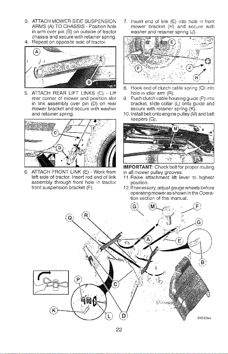
3. ATTACH MOWER SIDE SUSPENSION
ARMS (A) TO CHASSIS - Position hole
in arm over pin (B) on outside of tractor
chassis and secure w_th retainer spr_ng.
4. Repeat on opposite stcie of tractor.
5. ATTACH REAR LIFT LINKS (C) o Lift
rear corner of mower and position slot
in hnk assembly over pin (D) on rear
mower bracket and secure wEth washer
and retainer spnng,
7. Insert end of link /E) into hole in front
mower bracket (H) and secure w_th
washer and retainer spring /J).
8, Hook end of clutch cablespr;ng (Q) into
hole In tdler arm (R).
9 Push clutch cable housing guide IP) _nto
bracket, slide collar (L) onto gu{de and
secure wtth retainer spring (K).
10. Install belt onto eng}ne pulley (M) and belt
keepers (G).
6. ATTACH FRONT LINK (E) - Work from
left stde of tractor. Insert rod end of link
assembly through front hole in tractor
front suspension bracket (F).
IMPORTANT: Check beit for proper rout=ng
in all mower pulley grooves.
11,Raise attachment ttft lever to h=ghest
pos=fion.
12, If necessary, adiust gauge wheels before
operattng mower as shown inthe Opera-
tion section of thEs manual.
/
D)
03042te_
22
Loading ...
Loading ...
Loading ...