Loading ...
Loading ...
Loading ...

- 16 - - 9 -
5. HEALTH AND SAFETY INFORMATION
LOCATION:
1. Posture
Ensure when mounting the machine that the chosen location does not lead to unhealthy
posture or repetitive strain during normal operation.
2. Lighting
Adequate lighting must be provided to ensure no operations are light impaired possibly
leading to injury. Light should be from multiple sources to avoid any strobing effects from
flourescent or LED sources.
3. Reach
Do not reach over or around the machine at any time.
UNEXPECTED START-UP:
1. Remove the plug
Remove the plug from the socket before carrying out adjustment, servicing or maintenance.
ERRORS OF FITTING:
1. Tools
Ensure a suitable tool for the job in hand is securely and correctly fitted prior to starting the
machine.
Guards shall be fitted and in place at all times.
STABILITY:
1. Toppling
The drill shall be securely bolted down to a suitable and level surface to prevent the machine
from overturning leading to injury.
2. Slipping
Ensure the area is clean of any residue cutting/lubrication fluid and other materials which
may lead to a slip, trip or other such hazard.
5.3 CONNECTION TO THE POWER SUPPLY
Make sure the power supply information on the machine’s rating plate are compatible with the
power supply you intend to connect it to.
The Drill comes supplied with a UK standard 3 pin plug fitted. It is designed for connection to a
domestic power supply rated at 230V AC.
Because it is constructed mostly of metal parts, it is a Class 1 machine; meaning, it must have
an earth connection in the power supply. This is to prevent electrocution in the event of a
failure.
Apart from replacing the fuse in the plug, no other electrical work is recommended on this drill.
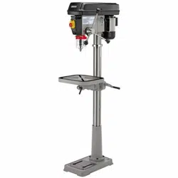
9. SETTING THE BENCH DRILL
FIG.14
FIG.15
%
9.2 DRILL BIT INSTALLATION/
REPLACEMENT - FIG. 14
The drilling machine is equipped with a geared
chuck and a separate key to secure the bit in
the chuck jaws.
Selection of the correct accessory is dependent
on material type and the intended application.
Ensure the selected accessory is suitable and
speed compatible with the drilling machine.
Place the bit into the chuck. Insert the chuck
key into apertures % engaging the
teeth.
Rotate the key clockwise to grip. All three
apertures should be tightened to make certain
of a firm grip.
Always use a good quality sharp drill bit/cutter.
WARNING: The drill bit will be hot after use.
9.3 NO-VOLT SWITCH - FIG. 15
In the event of a power supply disruption the
machine will require manually restarting once
power has been returned.
To switch the machine on, press the green
button marked ‘I’
To switch the machine off, press the red button
marked ‘O’. However, the yellow cover with
integral red stop button must be left covering
the switches so, in the event of an accident or
emergency striking the stop button will activate
the off switch.
Prior to starting the drilling machine make a
visual check, to ensure the guards are in place
and correctly functioning, the bit is correctly
installed with the chuck key removed and no
other parts are damaged proving a potential
hazard.
Ensure all locking handles are tight prior to
starting the drilling machine.
Loading ...
Loading ...
Loading ...