Loading ...
Loading ...
Loading ...
8. ASSEMBLY
8. ASSEMBLY
- 12 - - 13 -
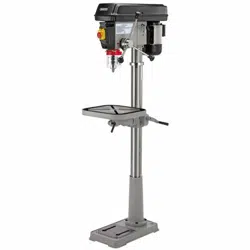
FIG.1
WARNING: The headstock, and consequently
when fully assembled the drilling machine,
are extremely heavy. Care shall be taken
when manoeuvring. The use of a hoist should
be employed to ensure safety.
NOTE: Remove the plug from the socket
before carrying out adjustment, servicing or
maintenance.
8.1 BASE TO COLUMN -
FIGS. 1 - 3
Align the column base onto the base
and secure with the four 16mm bolts
.
NOTE: Do not overtighten the bolts as this
may crack the casting.
Lock column to column base with grub screw
$.
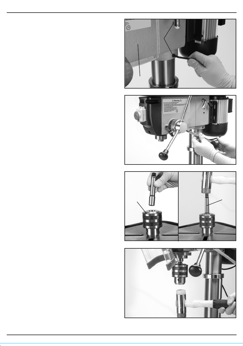
FIG.2
FIG.3
$
FIG.4
8.2 TABLE - FIG. 4
Slot the table into the table bracket and tighten
locking handle .
FIG.5
$
FIG.6
FIG.7
FIG.8
8.3 HEADSTOCK - FIG. 5
WARNING: The headstock assembly poses a
significant health and safety hazard while
being lifted and positioned into place. Seek
assistance.
Lift the headstock onto the top of the
column. When aligned and located down
onto the column fully, tighten grub screws
$ with the hex. key supplied.
NOTE: Adjust the drill head over the table
and base before securing. The use of a level
may be beneficial to improve accuracy.
8.4 PLUNGE HANDLES - FIG. 6
Screw plunge handles onto hub, hand
tighten.
8.5 CHUCK AND ARBOR -
FIGS. 7-8
The drill chuck, arbor and headstock spindle
join together with an interference fit formed by
the matched tapers of the mating surfaces.
Ensure all mating surfaces are clean as any
debris will cause the taper to mis-align
possibly resulting in the chuck or arbor
coming loose creating a potential hazard.
Using the chuck key provided open the chuck
until the jaws are completely recessed and
protected from damage.
Insert the short taper end of the arbor
into the back of chuck . A sharp tap with a
soft blow mallet will securely join them
together.
NOTE: Ensure the chuck is on a surface that
will not absorb the force of the mallet. If the
chuck does not mate securely, repeat the
process.
Insert the long taper end of arbor (P) into the
spindle. Rotate the chuck assembly until the
arbor locates allowing complete insertion.
Tap the chuck to securely locate it in place.
FIG.7b
Loading ...
Loading ...
Loading ...