Loading ...
Loading ...
Loading ...
9
E
N
G
L
I
S
H
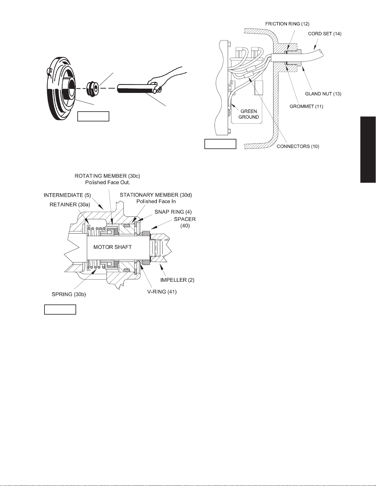
Lightly oil stationary member (30d), and with lapped surface
facing motor, press stationary member (30d) with seal pusher
into intermediate (5) until it seats against rotating member
(30c) and replace snap ring (4), see FIGURE 4.
Place v-ring (41) and seal spacer (3) onto shaft until seated.
Assemble volute and impeller as outlined in paragraph
F-2.2.
Assemble cord set (14) into housing end piece (21) as
outlined in paragraph F-5. Assemble screen (7) as outlined in
paragraph F-3.2. Replace oil as outlined in paragraph F-1.3
and pressure test per paragraph F-1.4.
F-5) Cord Assembly:
Place gland nut (13), one friction ring (12), grommet (11) onto
cord and slide cord through housing end piece (21). Make
wire connections as outlined in paragraph C-3, FIGURE 2,
using terminal connectors (10). Place o-ring (26) into groove
on housing end piece (21) and slide end piece (21) into
housing tube (27) being careful not to cut or damage o-ring
(26). Place pump support (25) onto the lower studs (28)
and place lock washers (23) and hex nuts (22) onto studs
(28) and tighten. Insert grommet (11), friction ring (12) into
housing end piece (21). Apply pipe sealant to gland nut (13)
and screw into housing end piece (21). Torque gland nut (13)
to 17.5 ft. lbs. to prevent water leakage see FIGURE 6.
SECTION: G REPLACEMENT PARTS
G-1 ORDERING REPLACEMENT PARTS:
When ordering replacement parts, ALWAYS furnish the
following information:
1. Pump serial number and date code. (G-4)
2. Pump model number. (G-3)
3. Pump part number.(G-2)
4. Part description.
5. Item part number.
6. Quantity required.
7. Shipping instructions.
8. Billing Instructions.
G-2 PART NUMBER:
The part number consist of a six (6) digit number, which
appears in the catalog. A one or two letter suf! x may follow
this number to designate the design con! guration. This
number is used for ordering and obtaining information.
G-3 MODEL NUMBER:
This designation consist of numbers and letters which
represents the discharge size, series, horsepower, motor
phase and voltage, speed and pump design. This number is
used for ordering and obtaining information.
G-4 SERIAL NUMBER:
The Serial Number block will consist of a six digit number,
which is speci! c to each pump and may be preceded by
a alpha character, which indicates the plant location. This
number will also be suf! xed with a four digit number, which
indicates the date the unit was built (Date Code).
EXAMPLE: A012345 0490.
Reference the six digit portion (Serial Number) of this number
when referring to the product.
Stationary Member (30d)
Polished Face Out
Intermediate (5)
Seal Pusher
FIGURE 4
FIGURE 5
FIGURE 6
Loading ...
Loading ...
Loading ...