Loading ...
Loading ...
Loading ...
Part No. 80106286
Revision C
37
Maintenance
Electronic Governing Check
12. After setting the proper clearance, hold the adjusting
screw while torquing the locknut to 70 in-lb (8 N·m).
13. Repeat these steps for cylinder no. 2.
14. Connect the negative (-) cable at the battery.
15. Install the 15-amp fuse into the fuse holder.
16. Close and lock the roof.
17. Restore utility power to the generator.
18. Push the ON/OFF switch on the back of the
generator to the ON (I) position.
19. Set the generator mode to auto.
Figure 24
Electronic Governor System
The engine electronic governor system oers improved
control and increased generator performance compared
to mechanically governed systems. The result is a smooth
steady-state operation without the “hunting” common to
many mechanical governors. The system also reduces
speed variations under engine loading and unloading
and significantly reduces frequency fluctuation when the
engine runs under higher loads.
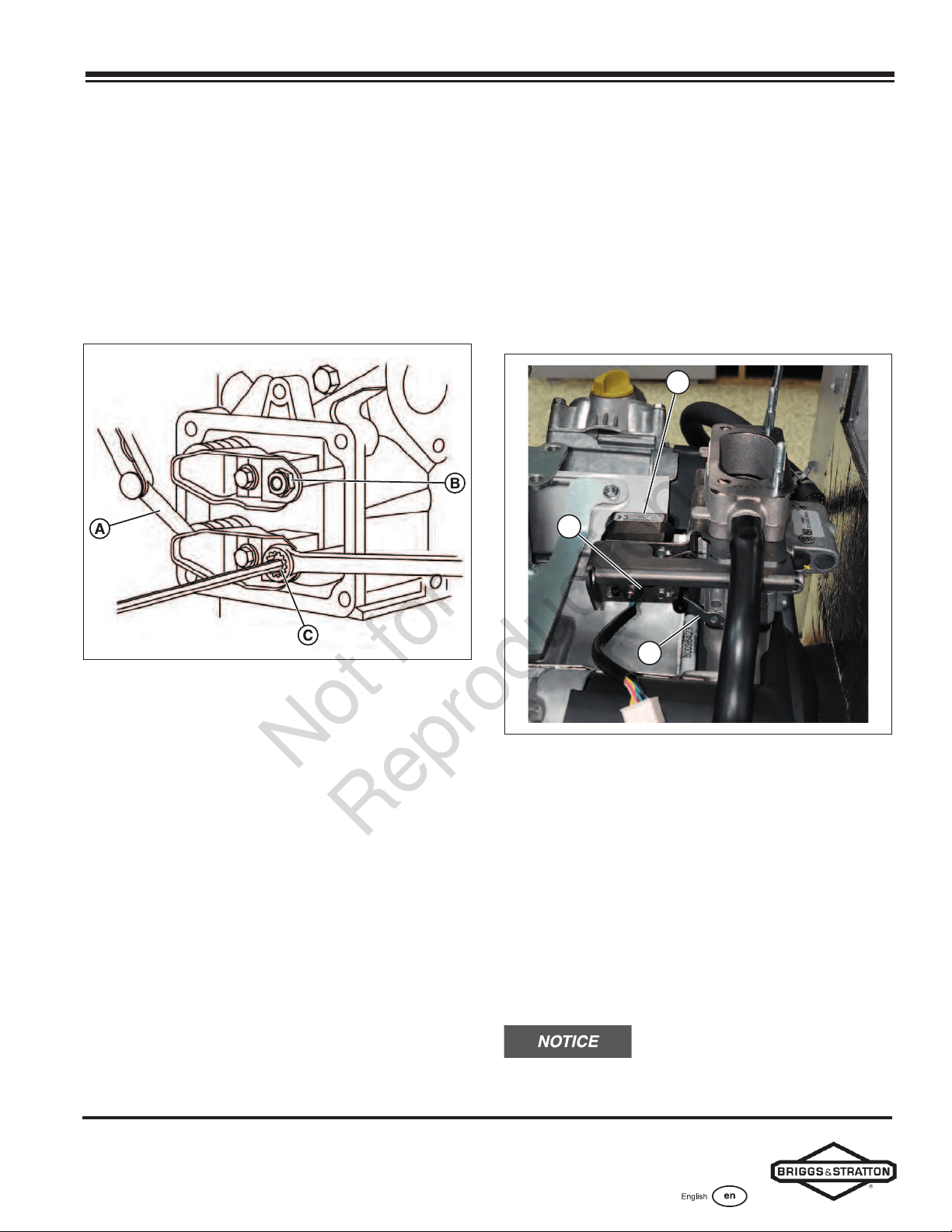
The electronic governor system features a stepper motor
(B), stepper motor throttle control linkages (C), and
throttle side linkage (A). The controller contains a digital
controller that processes engine speed information and
sends appropriate commands to the stepper motor to
control the position of the engine throttle.
Since the electronic governing system controls the
engine throttle demand based on generator load, the
following service codes and/or conditions could arise
from an electronic governing system issue:
• Engine does not start
• Overspeed
• Under-frequency
• Unstable no-load engine control
While troubleshooting any of these conditions, use the
controller’s actuator test to initiate a verification of the
electronic governor system.
B
A
C
Figure 25
Electronic Governing Check
The generator has an electronic governing check feature
that will turn on the stepper motor and move the throttle
linkage clockwise and counterclockwise within the
throttle limits. The test will rotate the stepper motor and
move the throttle arm between the wide open throttle and
dead idle limits for up to ten seconds. This check lets you
visually verify whether or not the stepper motor functions
correctly and whether or not the control linkages are
connected. The engine will not attempt to start during
this test. If the stepper motor does not move or if a
linkage binds, the generator requires service.
If the stepper motor does not move,
ensure the stepper motor connector is attached.
Not for
Reproduction
Loading ...
Loading ...
Loading ...