Loading ...
Loading ...
Loading ...
26
Part No. 80106286
Revision C
InstallationElectrical Field Connections
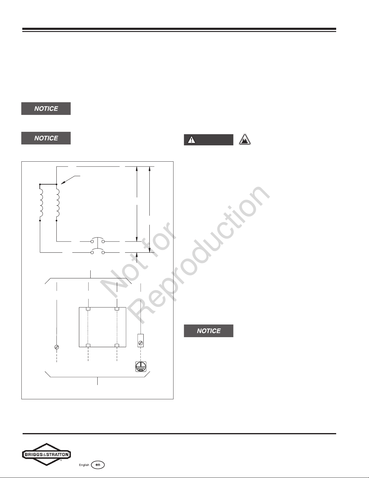
Generator AC System Connection
The generator uses a single-phase, three-wire AC
connection system. The stator assembly consists of a
pair of stationary windings with two leads appearing
from each winding. The junction of leads 22 and 33 forms
the neutral lead, as shown schematically and as a wiring
diagram.
Neutral is not bonded to the ground at
the generator.
Only use the generator with a listed
transfer switch that is compatible with the generator.
240V
11
22
44
120V
120V
1122 44 0
Neutral
Circuit
Breaker
Circuit
Breaker
NL2L1
Power Winding
To Tr ansfer Switch
To Alternator
To Chassis
Ground
Figure 15
Grounding the Generator
Unless mandated by local code, additional chassis
grounding to earth at the generator is not required. Any
grounding at the generator must use metal piercing lock
washers (or their equivalent). Also, any listed terminals
must be installed per the terminal supplier’s instructions.
All grounding and terminal installations must comply with
national electrical codes and local requirements.
Power Connections from the Generator to
the Transfer Switch
WARNING
Failure to isolate the
generator from the utility power could result in death
or serious injury to electric utility workers due to the
backfeed of electrical energy.
• Use a listed transfer switch to connect to a
building’s electrical system.
Utility Circuit Connection
Route all 240V utility leads in conduit. The 240V utility
leads deliver power to the generator’s circuit board, and
optional battery, oil sump, and fuel regulator warmers.
This power also charges the battery. The generator starts
when power on these leads is lost. Using the installer-
supplied minimum 300V #14 AWG (2.50 mm2) wire,
connect each control circuit terminal in the generator
(25 and 26) to the fuse block in the automatic transfer
switch.
Generator Power Connection
Using the installer-supplied minimum 300V wires and the
table located in the Electrical Field Connections section,
connect the generator power output L1, L2, neutral (N),
and ground to the corresponding L1, L2, neutral (N), and
ground in the transfer switch.
Refer to the National Electric Code
(NEC) for correct electrical field connections and wire size
calculations.
Not for
Reproduction
Loading ...
Loading ...
Loading ...