Loading ...
Loading ...
Loading ...
28
Part No. 80106286
Revision C
InstallationInitial Start-Up (No Load)
System Controller
See the separate online manual titled
Operation Instructions GC1030 SERIES GENSET Controller
(part number 80086364) for details on setup and
operation.
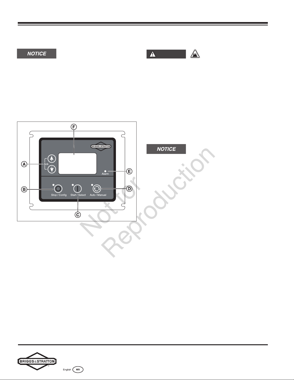
The generator controller, located inside the generator
housing, appears in the following figure.
Controls Used During Installation
Generator Controller
Figure 16
(A) Menu/Programming Navigation Buttons
(B) Stop/Config Button
(C) Start/Select Button
(D) Auto/Manual Button
(E) Alarm
(F) Digital Display — Displays generator mode, menu options,
and alarms
Detailed descriptions of the controls appear in the
Description of Control Keys section of the online manual
titled Operation Instructions GC1030 SERIES GENSET
Controller (part number 80086364).
Initial Start-Up (No Load)
WARNING
Exhaust heat/gases could
ignite combustibles, causing a fire and resulting in
death or serious injury.
• Remove all combustible materials from in and
around the generator compartment.
The unit has been set up for natural gas operation at
the factory. To complete fuel conversion, do so before
performing the following steps. See the Fuel Conversion
section.
Before operating the standby generator or putting it into
service, inspect the entire installation carefully. Then
begin testing the system without any electrical loads
connected, as follows:
When the generator starts for the very
first time, it purges air from the gaseous fuel lines. This
process can cause the engine to run roughly for a few
minutes.
1. Remove the two screws (A) retaining the control box
wiring cover. Remove the cover.
2. Connect an accurate multimeter to the line side of
the generator’s main circuit breaker.
3. Set the generator’s main circuit breaker to the ON
(closed) position.
4. Install a 15-amp fuse in the fuse holder below the
controller.
5. Push the start/select button on the controller. The
engine starts in Low Idle Mode (LIM).
6. Push the button again to bring the engine to full
speed.
7. Listen for unusual noises, vibrations, or other
indications of abnormal operation. Check for oil leaks
while the engine runs.
8. Let the engine warm up for approximately five
minutes to allow the internal temperatures to
stabilize.
9. Check the generator output at the load side of the
circuit breaker. The voltage should be 225-250 volts
and the frequency should be 59.0-61.0 Hz.
10. Check the generator output between one generator
connection lug and a neutral lug, then between the
other generator connection lug and a neutral lug. In
both cases, the voltage reading should be 112-125
volts.
Not for
Reproduction
Loading ...
Loading ...
Loading ...