Loading ...
Loading ...
Loading ...
24
Part No. 80106286
Revision C
InstallationElectrical Field Connections
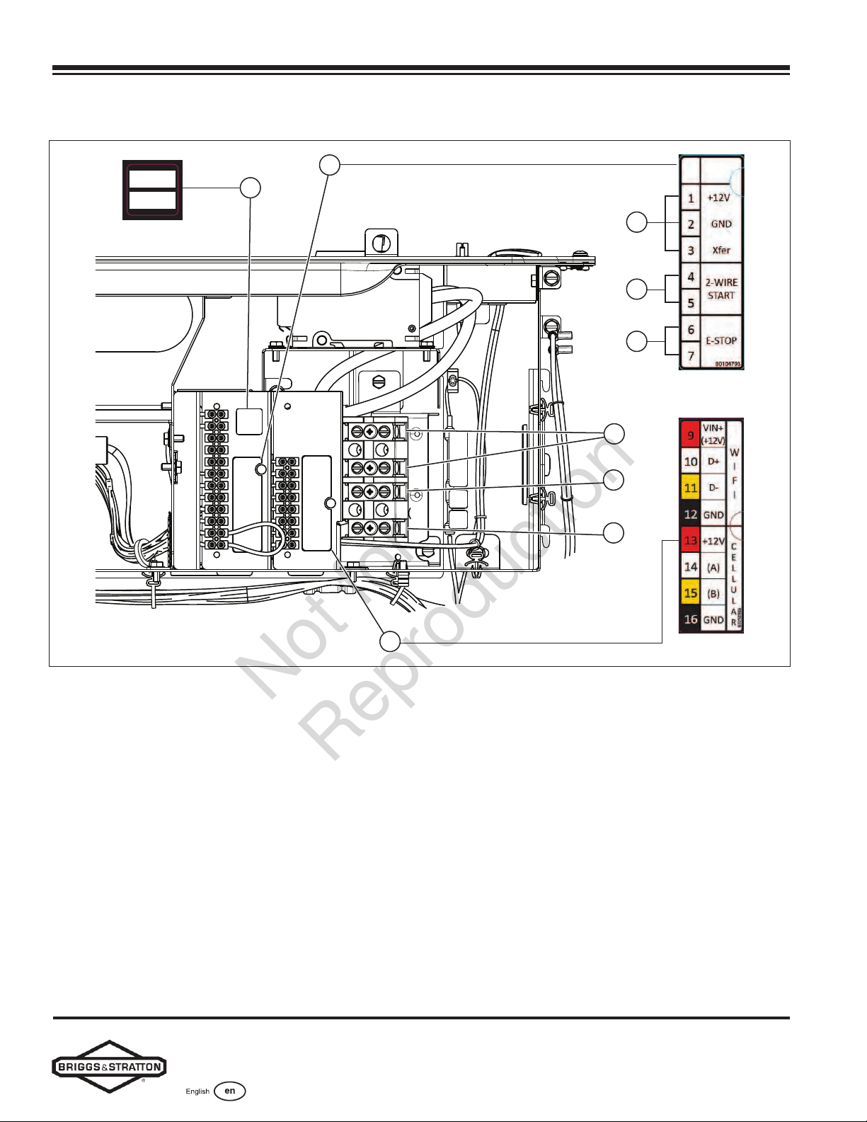
System Connector Location
H
G
E
A
J
B
C
D
F
25
26
80014586
Figure 14
Legend for System Connector Location:
(A) Utility Connection — Connects utility 240VAC from the fuse
block in ATS to the controller. Connect only one wire per
terminal. Use #14 AWG (2.50 mm2) minimum 300V wire
(B) Transfer Switch Connection — Controls the transfer switch
contactor
(C) Two-wire Start — Helps provide optional remote start
contact
(D) E-Stop — Use with the optional external E-Stop
(E) Field Connections Terminal Block - Reference the following
table
(F) Power Connection (L 1 and L2) — Oers power
connection to the transfer switch
(G) Ground Connection — Connects to the transfer switch
ground wire
(H) Neutral Connection — Connects to the transfer switch
neutral wire
(J) Communications Terminal Block — Reference the
following table
Not for
Reproduction
Loading ...
Loading ...
Loading ...