Loading ...
Loading ...
Loading ...
63
1/2"
(12.7)
15.4 15.8
5/8"
(15.9)
18.6 19.1
3/4" (19) 22.9 23.3
After flared the pipe, the opening part must
be seal by end cover or adhesive tape to
avoid duct or exogenous impurity come into
the pipe.
7. Drill holes if the pipes need to pass the
wall.
8. According to the field condition to bend the
pipes so that it can pass the wall smoothly.
9. Bind and wrap the wire together with the
insulated pipe if necessary.
10. Set the wall conduit
11. Set the supporter for the pipe.
12. Locate the pipe and fix it by supporter
For horizontal refrigerant pipe, the distance
between supporters should not be exceed
1m.
For vertical refrigerant pipe, the distance
between supporters should not be exceed
1.5m.
13. Connect the pipe to indoor unit and outdoor
unit by using two spanners.
Be sure to use two spanners and proper
torque to fasten the nut, too large torque
will damage the flare, and too small torque
may cause leakage. Refer the following
table for different pipe connection.
Pipe
Diameter
Torque Sketch map
(kgf.cm) (N.cm)
1/4" (6.35) 144~176 1420~1720
3/8" (9.52) 333~407 3270~3990
1/2" (12.7) 504~616
4
950~6030
5/8" (15.9) 630~770 6180~7540
3/4" (19) 990~1210 9270~11860
12.4.3 Installation for the first time
Air and moisture in the refrigerant system have
undesirable effects as below:
● Pressure in the system rises.
● Operating current rises.
● Cooling or heating efficiency drops.
● Moisture in the refrigerant circuit may
freeze and block capillary tubing.
● Water may lead to corrosion of parts in the
refrigerant system.
Therefore, the indoor units and the pipes
between indoor and outdoor units must be leak
tested and evacuated to remove gas and
moisture from the system.
Gas leak check (Soap water method):
Apply soap water or a liquid neutral detergent
on the indoor unit connections or outdoor unit
connections by a soft brush to check for
leakage of the connecting points of the piping. If
bubbles come out, the pipes have leakage.
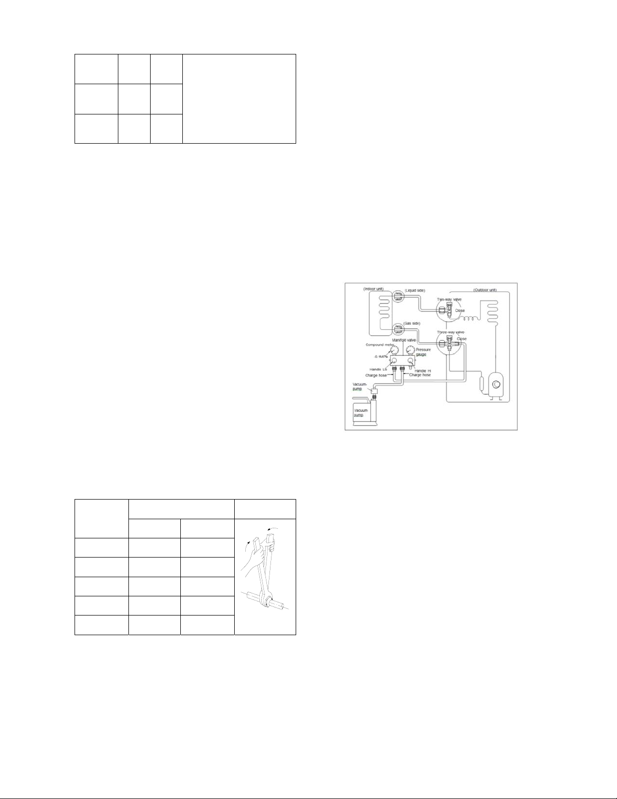
1. Air purging with vacuum pump
1) Completely tighten the flare nuts of the
indoor and outdoor units, confirm that both
the 2-way and 3-way valves are set to the
closed position.
2) Connect the charge hose with the push pin
of handle lo to the 3-way valves gas service
port..
3) Connect the charge hose of handle hi
connection to the vacuum pump.
4) Fully open the handle Lo of the manifold
valve.
5) Operate the vacuum pump to evacuate.
6) Make evacuation for 30 minutes and check
whether the compound meter indicates
-0.1Mpa (14.5Psi). If the meter does not
indicate -0.1Mpa (14.5Psi) after pumping 30
minutes, it should be pumped 20 minutes
more. If the pressure can’t achieve -0.1Mpa
(14.5Psi) after pumping 50 minutes, please
check if there are some leakage points.
Fully close the handle Lo valve of the
manifold valve and stop the operation of the
Loading ...
Loading ...
Loading ...