
Loading ...
Loading ...
Loading ...
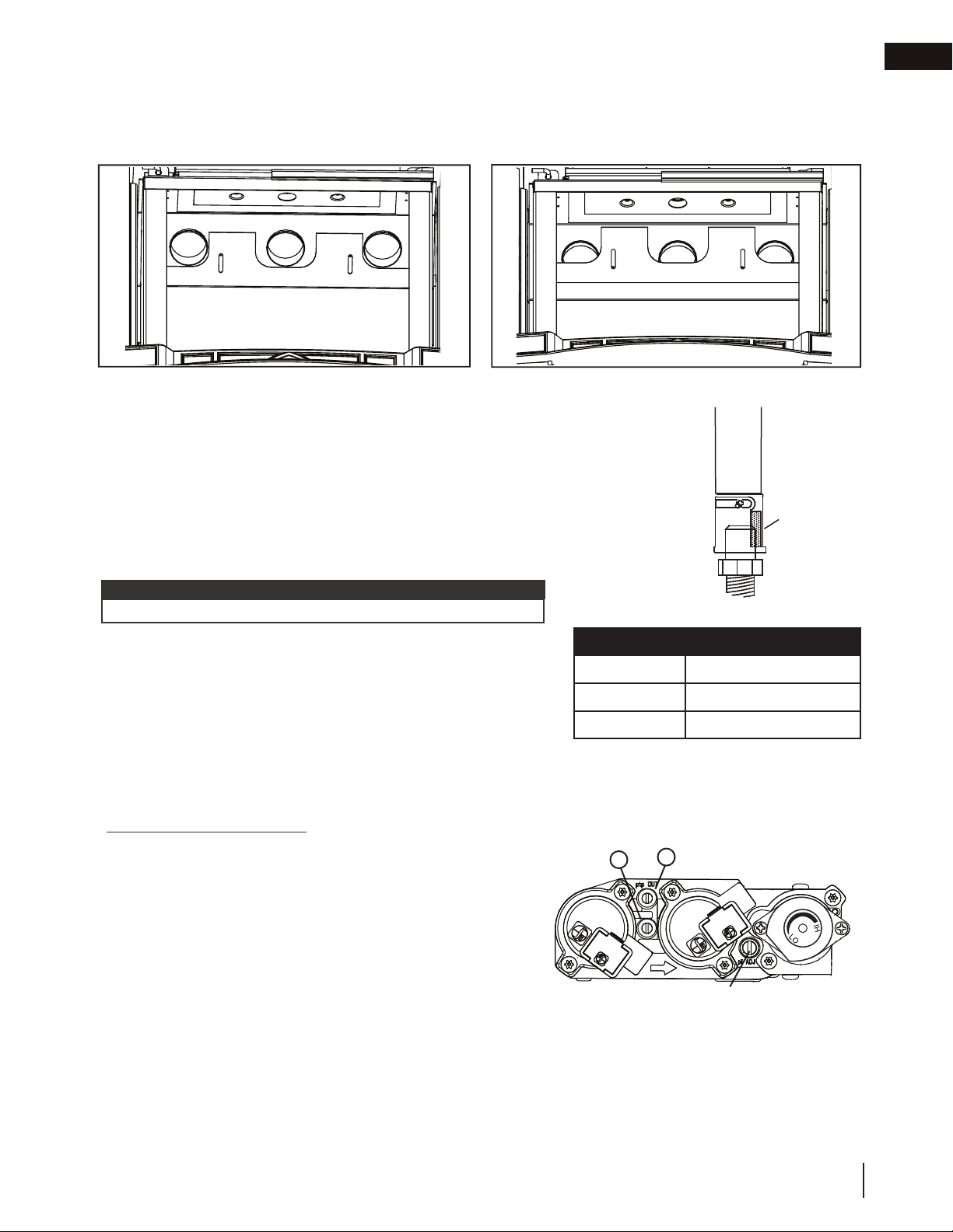
Remove the 2 screws securing the burner. Air shutters have been factory
set open according to the Venturi Adjustment Chart. These settings are for
(maximum) horizontal termination. Adjustment may be required depending
on fuel type, vent confi guration and altitude. After making adjustments
replace the burner ensuring that the venturi tube
fi ts over the orifi ce and replace the screws.
VENTURI ADJUSTMENT CHART
FUEL GDS25-1
NG 5/16” (8mm)
P 7/16” (11mm)
8.0 adjustment
This appliance has an air shutter that has been factory set open according to
the chart below:
Regardless of venturi orientation, closing the air shutter will cause a more
yellow flame, but can lead to carbonization. Opening the air shutter will cause
a more blue flame, but can cause flame lifting from the burner ports. The flame
may not appear yellow immediately; allow 15 to 30 minutes for the final flame
colour to be established.
AIR SHUTTER ADJUSTMENT MUST ONLY BE DONE BY A QUALIFIED
INSTALLER.
AIR
SHUTTER
OPENING
VENTURI
BURNER
ORIFICE
It is important that the orifice is securely inserted into the venturi.
note:
RESTRICTOR SHOWN IN A
FULLY OPEN POSITION
RESTRICTOR SHOWN IN A
FULLY CLOSED POSITION
Vertical installations may display a very active fl ame. Loosen the two screws and slide the restrictor plate blocking the
exhaust path. This reduces the velocity of the exhaust gases, slowing down the fl ame pattern and creating a more
traditional fl ame appearance. For vertical vents greater than 15 ft (5m), this restrictor must be fully closed.
8.1 restricting vertical vents
8.2 venturi adjustment
8.3 pilot burner adjustment
Adjust the pilot screw to provide properly sized fl ame. Turn in a clockwise direction to reduce the gas fl ow.
Check Pressure Readings:
Inlet pressure can be checked by turning screw (A) counter-
clockwise 2 or 3 turns and then placing pressure gauge tubing
over the test point. Gauge should read as described on the chart
below. Check pressure with main burner operating on “HI”.
Outlet pressure can be checked the same as above using screw
(B). Gauge should read as described on the chart below. Check
pressure with main burner operating on “HI”.
After taking pressure readings, be sure to turn screws
clockwise fi rmly to reseal. Do not overtorque.
Leak test with a soap and water solution.
INSERT PILOT ASSEMBLY
A
B
PILOT SCREW
EN
W415-2347 / C / 09.21.20
35
Loading ...
Loading ...
Loading ...