
Loading ...
Loading ...
Loading ...
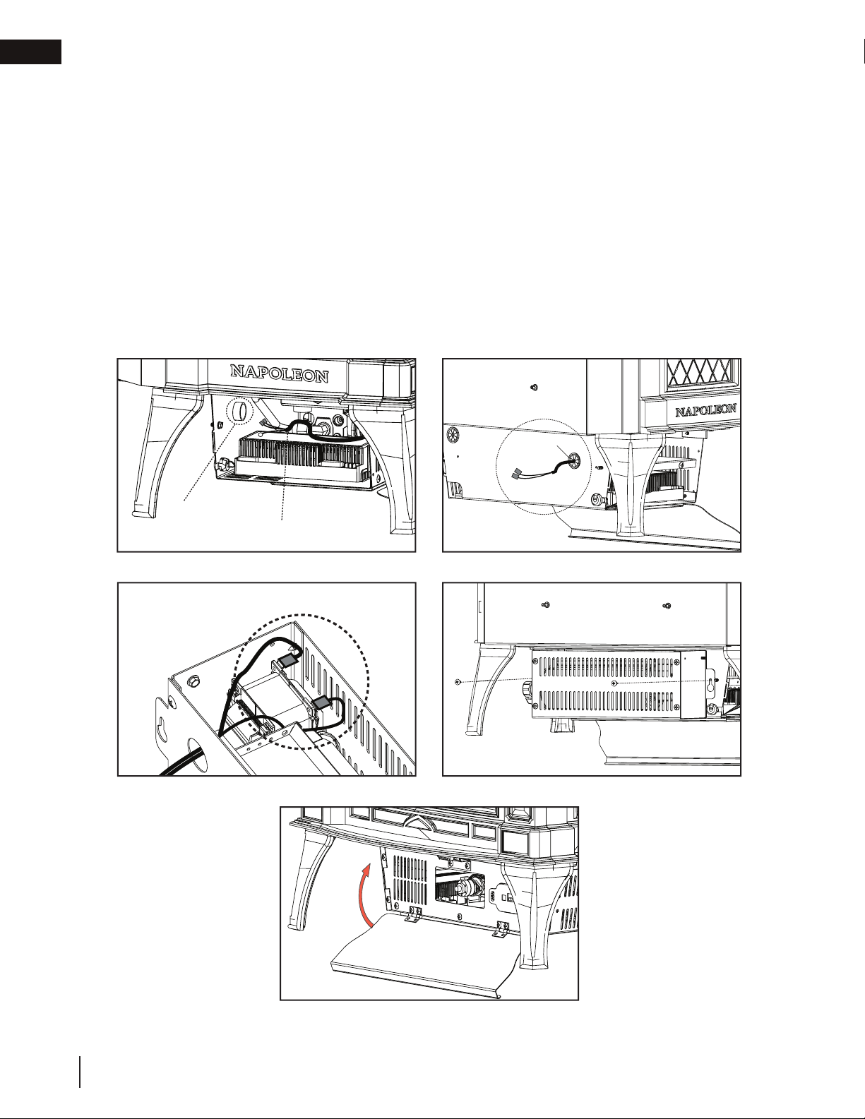
BUSHING
Spade Connectors
FIG. 6
FIG. 7
FIG. 8
FIG. 9
Rear Hole
Wire Harness
FIG. 5
E. Access blower wire leads. Remove 2 insulation connectors from blower wire leads.
F. Route the blower wire through the rear hole of the housing (FIG. 5 and 6).
G. Snap bushing over blower wire and press into rear hole of housing.
H. Place blower housing close to the rear of the appliance. Route wire through hole in blower housing and
connect the spade connectors to blower (FIG. 7).
I. Align the blower to the rear side of the control box and fasten it with 2 screws included with the kit
(FIG. 8).
J. Re-install control box side cover to the control box using the 2 screws previously removed in Step C.
K. Close the control door (FIG. 9).
L. Reconnect power supply to the appliance.
W415-2347 / C / 09.21.20
EN
28
optional blower installation
Loading ...
Loading ...
Loading ...