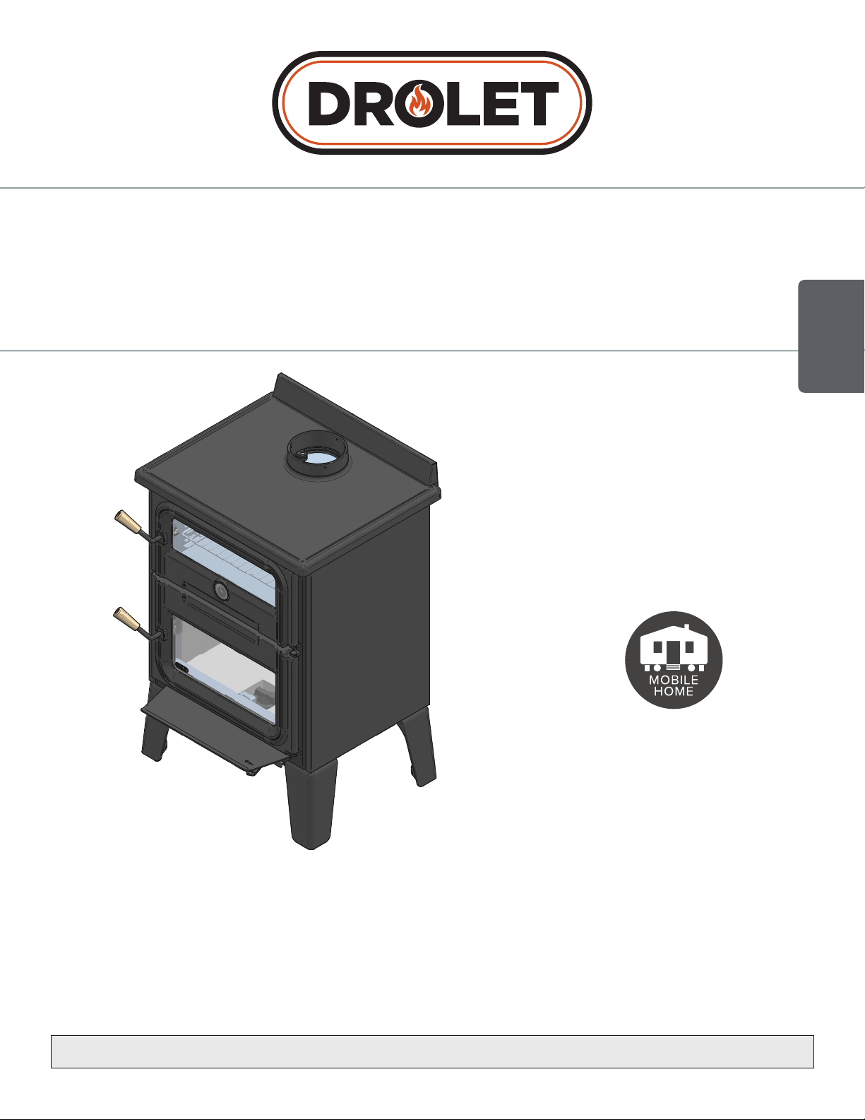
Installation and Operation Manual
BISTRO WOOD BURNING
COOKSTOVE
(DB04815 model)
Printed in Canada 45251A
2021-11-03
READ AND KEEP THIS MANUAL FOR REFERENCE
ENGLISH
Security test made according to
regulations ULC S627 and UL 1482
by an accredited laboratory.
MOBILE
HOME
CONTACT LOCAL BUILDING OR FIRE OFFICIALS ABOUT RESTRICTIONS AND INSTALLATION INSPECTION REQUIREMENTS
IN LOCAL AREA.
READ THIS ENTIRE MANUAL BEFORE INSTALLATION AND USE OF THIS WOOD STOVE. FAILURE TO FOLLOW THESE INSTRUCTIONS
COULD RESULT IN PROPERTY DAMAGE, BODILY INJURY OR EVEN DEATH.
U.S. ENVIRONMENTAL PROTECTION AGENCY: THIS UNIT IS NOT A CERTIFIED RESIDENTIAL WOOD HEATER. THE PRIMARY USE
FOR THIS UNIT IS FOR COOKING OR BAKING.
ISO PAGE 1


Page 3
Installation and operation manual - Bistro woodburning cookstove
ENGLISH
As one of North America’s
largest and most respected
wood stove and fireplace
manufacturers, Stove Builder
International takes pride in the
quality and performance of all
its products.
The following pages
provide general advice on
wood heating, detailed
instructions for safe and
effective installation, and
guidance on how to get the
best performance from this
cookstove.
It is highly recommended
that this cookstove be
installed and serviced by
professionals who are certified
in the United States by NFI
(National Fireplace Institute®)
or in Canada by WETT
(Wood Energy Technology
Transfer) or in Quebec
by APC (Association des
Professionnels du Chauffage).
Contact local building or fire
officials about restrictions
and installation inspection
requirements in your local
area.
A building permit might be
required for the installation
of this cookstove and
the chimney that it is
connected to. It is also highly
recommended to inform your
home insurance company.
Please read this entire manual
before installing and using this
cookstove.
THANK YOU FOR CHOOSING
THIS WOOD BURNING COOKSTOVE.
If this cookstove is
not installed properly,
combustible materials
near it may overheat
and catch fire.
To reduce the
risk of fire, follow
the installation
instructions in this
manual.
ONLINE WARRANTY REGISTRATION
If the unit requires repairs during the warranty period, proof of purchase must be provided. The
purchase invoice must be kept. The date indicated on it establishes the warranty period. If it
can not be provided, the warranty period will be determined by the date of manufacture of the
product.
It is also highly recommended to register the warranty online at
https://www.drolet.ca/en/warranty/warranty-registration/
Registering the warranty will help to quickly find the information needed on the unit.

Page 4
Installation and operation manual - Bistro woodburning cookstove
ENGLISH
TABLE OF CONTENTS
CERTIFICATION PLATE ................................................................................................................ 6
PART A - OPERATION AND MAINTENANCE .............................................................................. 7
1. Safety Information ................................................................................................................. 7
2. General information ............................................................................................................... 9
2.1 Specifications ............................................................................................................... 9
2.2 Cookstove Dimensions ................................................................................................10
3. Cookstove operation ........................................................................................................... 12
3.1 Components use ..........................................................................................................12
3.2 Gas path ......................................................................................................................15
4. Combustibles ....................................................................................................................... 16
4.1 Tree Species ................................................................................................................16
4.2 Log Length ..................................................................................................................17
4.3 Piece Size ....................................................................................................................17
4.4 Drying Time .................................................................................................................17
5. Efcient wood combustion ................................................................................................. 18
5.1 General Advice .............................................................................................................18
5.2 First Use ......................................................................................................................19
5.3 Lighting Fires ...............................................................................................................19
5.4 Combustion Cycles ......................................................................................................20
5.5 Rekindling a Fire ...........................................................................................................21
5.6 Air Intake Control .........................................................................................................21
6. Maintenance ........................................................................................................................ 23
6.1 Combustion Chamber ...................................................................................................23
6.2 Removing ashes ...........................................................................................................23
6.3 Grills and cast iron cooking surface ...............................................................................24
6.4 Cleaning and Painting ...................................................................................................24
6.5 Refractory Materials and Baffle ......................................................................................24
6.6 Glasses .......................................................................................................................25
6.7 Decorative Panels.........................................................................................................31
6.8 Optional Fresh Air Intake Kit Installation .........................................................................32
6.9 Air Tubes And Baffle Installation ....................................................................................33
6.10 Handles installation ......................................................................................................34
6.11 Mobile Home Installation ...............................................................................................35
6.12 Exhaust System ...........................................................................................................35

Page 5
Installation and operation manual - Bistro woodburning cookstove
ENGLISH
PART B - INSTALLATION ............................................................................................................. 37
7. General Information ............................................................................................................. 37
7.1 Security .......................................................................................................................37
7.2 Regulations Governing the Installation of the Cookstove .................................................38
7.3 Cookstove Positioning ..................................................................................................38
7.4 Location of the Certification Label .................................................................................38
8. Clearances to Combustible Material .................................................................................. 39
8.1 Floor Protection ...........................................................................................................42
8.2 Clearances Reduction to the Walls and the Ceiling .........................................................43
8.3 Clearances for Shield Installation ...................................................................................45
9. Evacuation System .............................................................................................................. 47
9.1 General Information ......................................................................................................47
9.2 Suitable Chimneys ........................................................................................................47
9.3 Minimum Chimney Height .............................................................................................49
9.4 Chimney Location .........................................................................................................49
10. Installing the Chimney Connector ....................................................................................... 51
10.1 Installation of Single Wall Chimney Connector ................................................................51
10.2 Installation of Double wall Chimney Connector ...............................................................53
11. Combustion Air .................................................................................................................... 54
11.1 Mobile home ................................................................................................................54
11.2 Conventional House .....................................................................................................55
12. Troubleshooting ................................................................................................................... 56
13. Parts List .............................................................................................................................. 57
Bistro Cooking Stove Limited Lifetime Warranty .......................................................................
60
Dealer:
Installer:
Phone Number:
Serial Number:

Page 6
Installation and operation manual - Bistro woodburning cookstove
ENGLISH
CERTIFICATION PLATE

Page 7
Installation and operation manual - Bistro woodburning cookstove
ENGLISH
PART A - OPERATION AND MAINTENANCE
U.S. ENVIRONMENTAL PROTECTION AGENCY: THIS UNIT IS NOT A CERTIFIED
RESIDENTIAL WOOD HEATER. THE PRIMARY USE FOR THIS UNIT IS FOR COOKING
OR BAKING.
1. Safety Information
• Operate only with doors fully closed. If door is left partly open, gas and flame may be drawn out of
the opening, creating risks from both fire and smoke.
• The cookstove is not designed to be used when the door is open. Open the door only to startup or
to reload the stove.
• Don’t leave unattended when the door is slightly open for startups. Always close the door after
ignition.
• HOT WHILE IN OPERATION, KEEP CHILDREN, CLOTHING AND FURNITURE AWAY.
CONTACT MAY CAUSE SKIN BURNS. GLOVES MAY BE NEEDED FOR COOKSTOVE
OPERATION.
• Using the cookstove with cracked or broken components, such as glass, firebricks or baffle may
produce an unsafe condition and may damage the cookstove.
• Open the air control fully before opening the combustion chamber door.
• Do not store fuel within cookstove minimum installation clearances.
• Do not store wood underneath the combustion chamber.
• Burn only seasoned natural firewood.
• Do not elevate the fire by using a grate.
• A smoke detector, a carbon monoxide detector and a fire extinguisher should be installed in the
house. The location of the fire extinguisher should be known by all family members.
• Paint used on this appliance is not food grade (including the cast iron cooking surface). It is strongly
not recommanded to cook directly on the painted surfaces.
• Radiant heat coming from the stove glass can cause intense heat or burning sensations. It is
recommanded to cook on the cast iron cooking surface from the side of the appliance.
• During cooking, keep the oven door closed to keep a constant temperature.
• Make sure the ash drawer is in place when the cookstove is in use (when it gives off heat).
Page 8
Installation and operation manual - Bistro woodburning cookstove
ENGLISH
• DO NOT USE CHEMICALS OR FLUIDS TO START THE FIRE.
• DO NOT BURN GARBAGE OR FLAMMABLE LIQUIDS SUCH AS GASOLINE, NAPHTHA,
FUEL OIL, ENGINE OIL, KEROSENE, CHARCOAL LIGHTER FUEL, SIMILAR LIQUIDS, OR
AEROSOLS TO START, REVIVE OR NEAR THE FIRE. KEEP ALL SUCH LIQUIDS WELL AWAY
FROM THE HEATER WHILE IT IS IN USE.
• This appliance should always be maintained and operated in accordance with these instructions.
WARNING: This product can expose you to chemicals including carbon monoxide,
which is known to the State of California to cause cancer, birth defects or other
reproductive harm. For more information go to www.P65warnings.ca.gov
Page 9
Installation and operation manual - Bistro woodburning cookstove
ENGLISH
2. General information
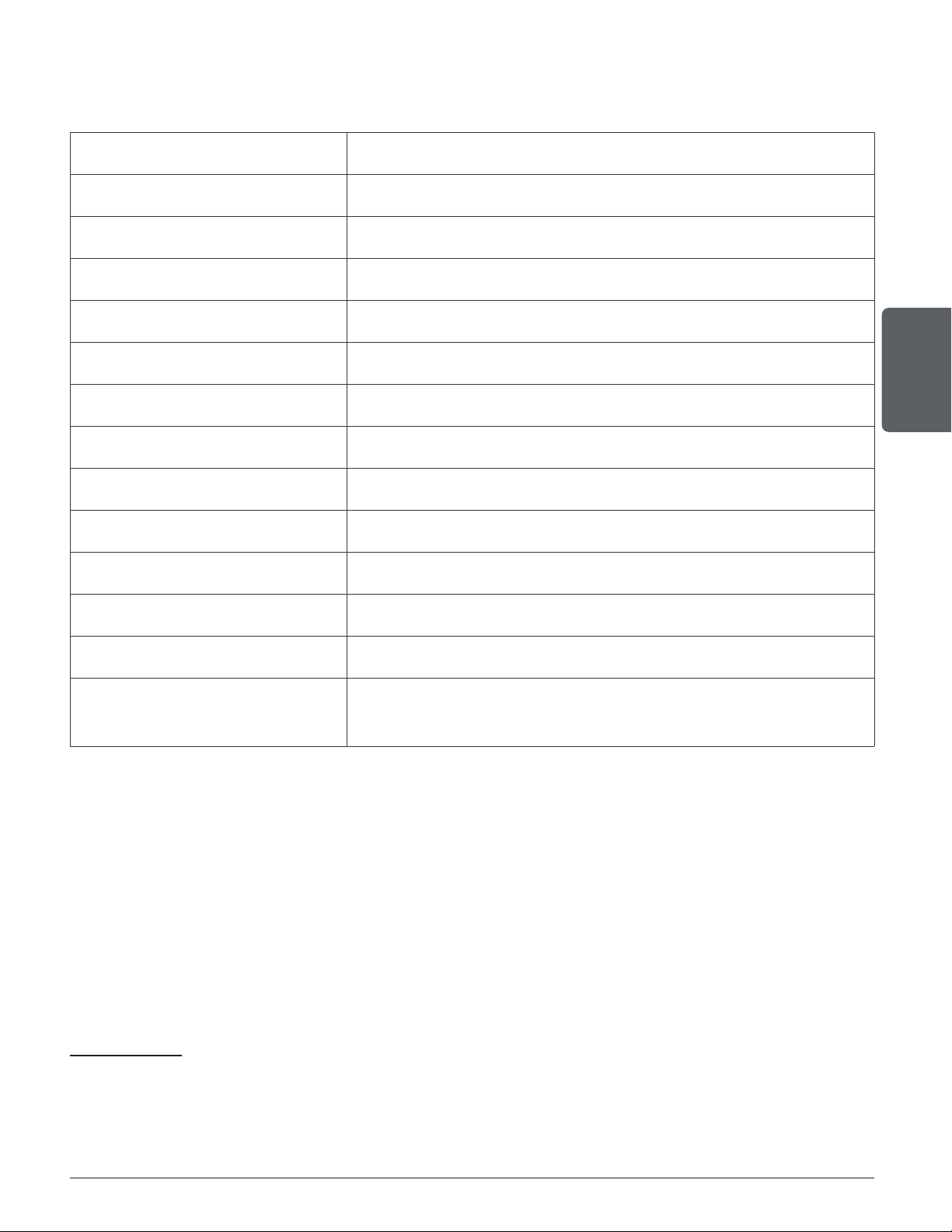
2.1 Specifications
Model Bistro woodburning cookstove (DB04815)
Fuel Type Dry Cordwood
Recommanded log length 16" (406 mm)
Maximum log length 20" (508 mm) east-west orientation
1
Flue outlet diameter 6 in (150 mm)
Chimney diameter 6 in (150 mm)
Type of chimney UL 103 HT, ULC S629
Necessary flue draft 0,05" H
2O (12 Pa)
Alcove installation Not approved
Mobile home installation
2
Approved
Shipping weight 575 lb (261 kg)
American standards (security) UL 1482
Canadian standards (security) ULC S627
Oven dimensions (W x D x H)
18" x 15-5/16" x 7-7/8"
457 mm x 177 mm x 381 mm
1
East-west orientation: longitudinal side of logs visible; north-south orientation: end of logs visible.
2
Mobile home (Canada) or prefabricated home (USA): The US department of Housing and urban development describes “prefabricated homes”
better known as “mobile homes” as follows; constructed buildings on fixed wheels and those transported on temporary wheels/axles installed on a
permanent foundation. In Canada, a mobile home is a dwelling which the assembly of each component is done or mostly done before moving it to a
location where it will be placed on foundations and connected to service facilities that meet the standards CAN/CSA-Z240 MH.
Page 10
Installation and operation manual - Bistro woodburning cookstove
ENGLISH
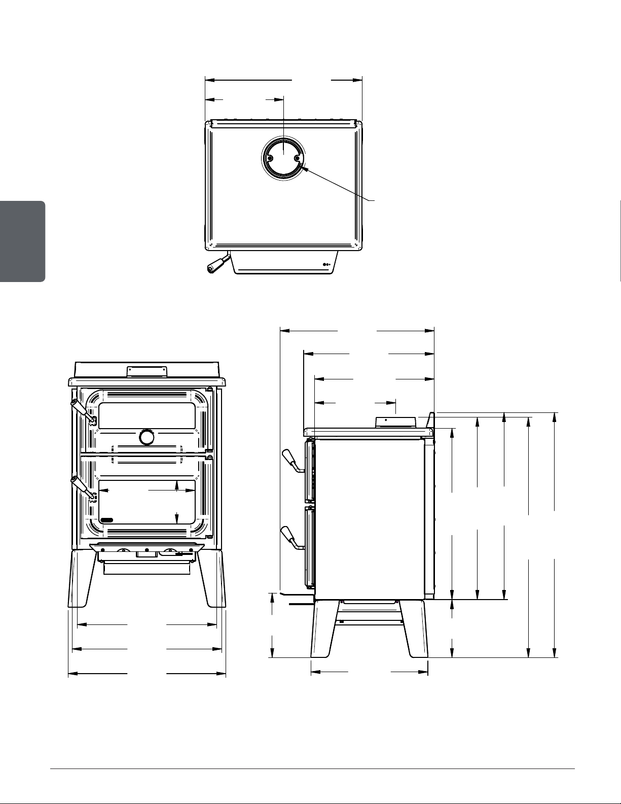
2.2 Cookstove Dimensions
13 7/16"
342mm
26 7/8"
683mm
O
6"
153mm
27"
686mm
23 7/8"
606mm
11 1/16"
280mm
20 1/16"
509mm
9 7/8"
251mm
29 5/16"
745mm
31 3/16"
792mm
32"
814mm
13 7/8"
353mm
20 7/16"
520mm
22 3/8"
568mm
26 3/8"
670mm
41 1/8"
1044mm
41 15/16"
1065mm
16 1/2"
419mm
7 7/16"
189mm
25 5/8"
651mm
Figure 1: Top view
13 7/16"
342mm
26 7/8"
683mm
O
6"
153mm
27"
686mm
23 7/8"
606mm
11 1/16"
280mm
20 1/16"
509mm
9 7/8"
251mm
29 5/16"
745mm
31 3/16"
792mm
32"
814mm
13 7/8"
353mm
20 7/16"
520mm
22 3/8"
568mm
26 3/8"
670mm
41 1/8"
1044mm
41 15/16"
1065mm
16 1/2"
419mm
7 7/16"
189mm
25 5/8"
651mm
13 7/16"
342mm
26 7/8"
683mm
O
6"
153mm
27"
686mm
23 7/8"
606mm
11 1/16"
280mm
20 1/16"
509mm
9 7/8"
251mm
29 5/16"
745mm
31 3/16"
792mm
32"
814mm
13 7/8"
353mm
20 7/16"
520mm
22 3/8"
568mm
26 3/8"
670mm
41 1/8"
1044mm
41 15/16"
1065mm
16 1/2"
419mm
7 7/16"
189mm
25 5/8"
651mm
Figure 2: Front view Figure 3: Side view
Page 11
Installation and operation manual - Bistro woodburning cookstove
ENGLISH
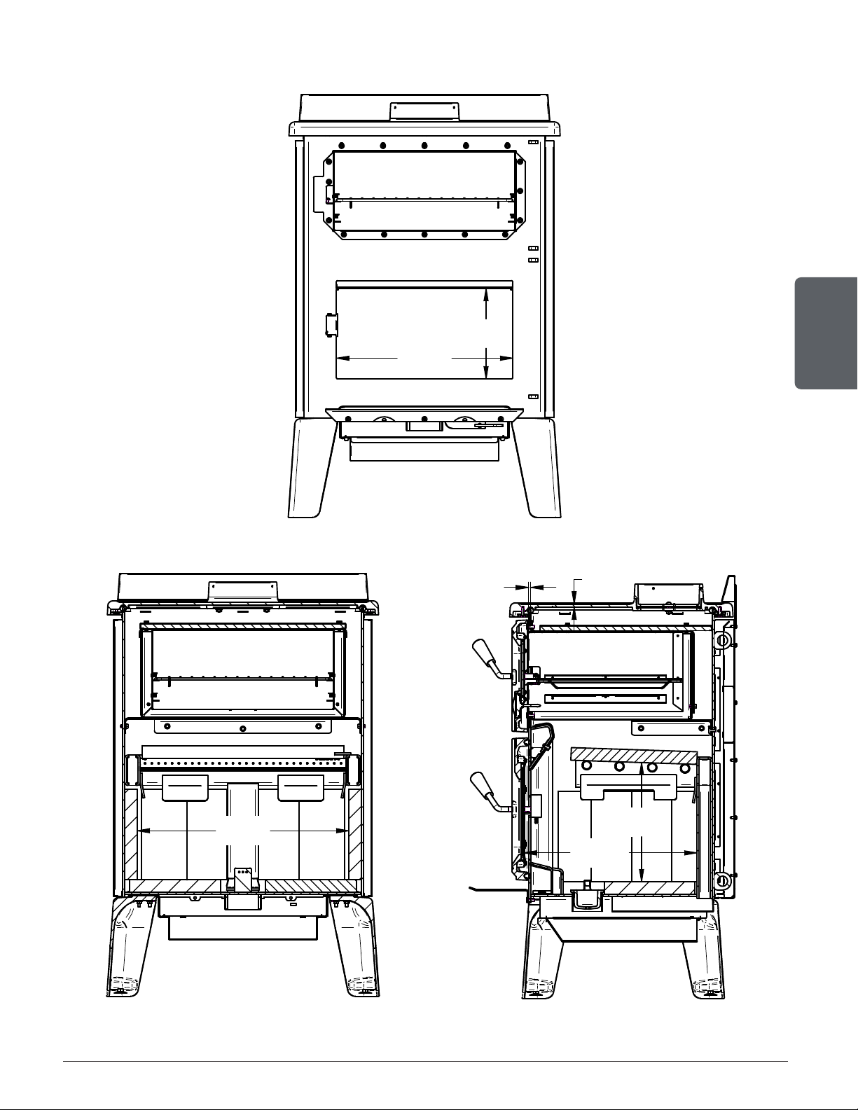
2.2.1 Combustion Chamber Dimensions
17 1/2"
444mm
9"
228mm
21"
533mm
17 3/16"
437mm
11 7/8"
301mm
5/16"
7mm
3/16"
5mm
Figure 4: Door opening
17 1/2"
444mm
9"
228mm
21"
533mm
17 3/16"
437mm
11 7/8"
301mm
5/16"
7mm
3/16"
5mm
17 1/2"
444mm
9"
228mm
21"
533mm
17 3/16"
437mm
11 7/8"
301mm
5/16"
7mm
3/16"
5mm
Figure 5: Front view : Combustion chamber Figure 6: Side view : Combustion chamber
Page 12
Installation and operation manual - Bistro woodburning cookstove
ENGLISH
3. Cookstove operation
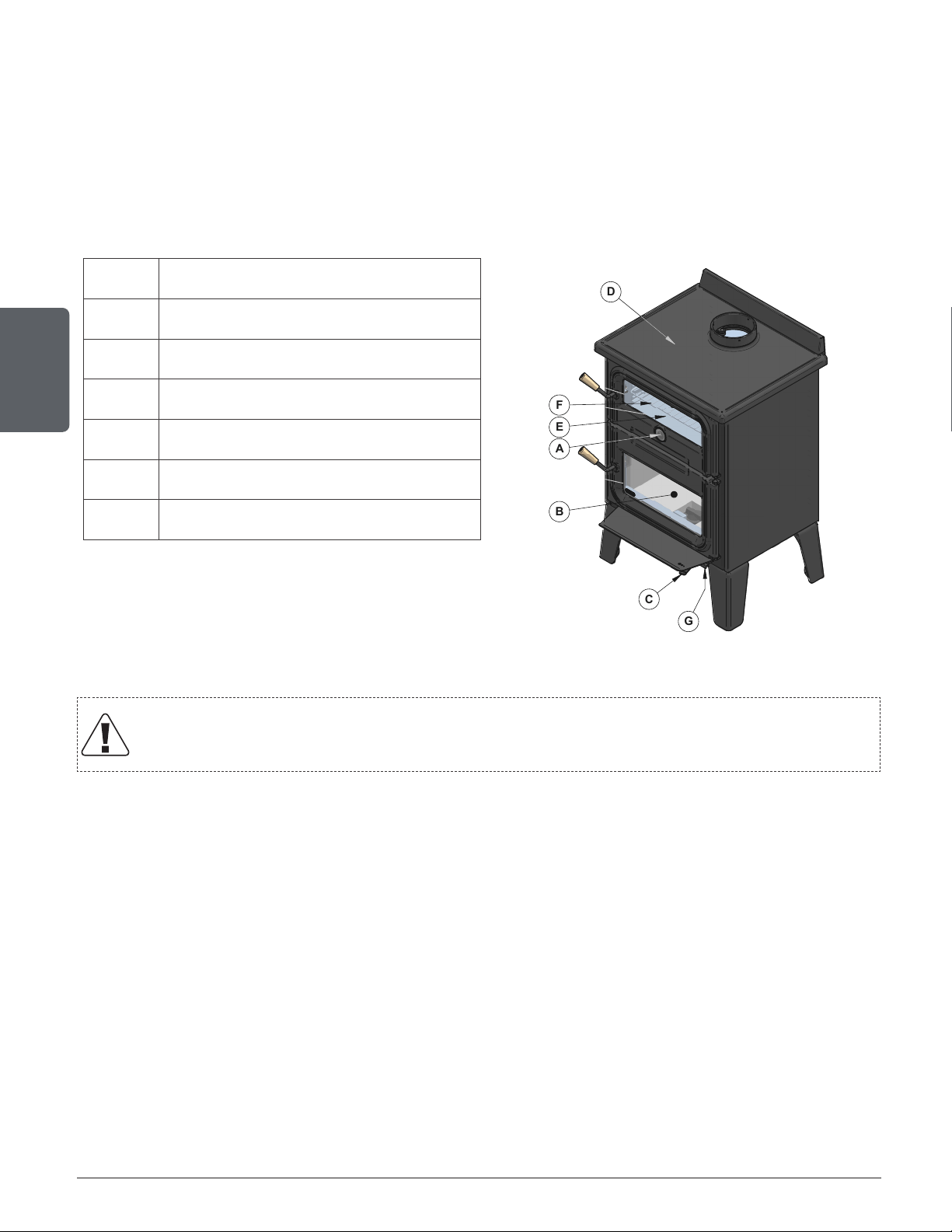
3.1 Components use
Cooking with a wood-burning cookstove is an art that requires several attempts to get to know
and control the appliance. Many factors can influence how the cookstove will heat the oven and
the cooking surface. Among them, the type of fuel used and its quality, the size of the logs and
when to load before cooking. It is therefore recommended to do several tests to make the Bistro
your own.
A Oven thermometer
B Combustion chamber
C Air control
D Cast iron cooking suface
E Stainless steel oven
F Cooking grills
G Ash pan
FIGURE 4
A
B
C
D
E
F
G
Figure 7: Component Location
It is prohibited to put or store inside the required appliance clearances: alcohol,
gasoline, liquid fuel, flammable materials, ashes, paper and wood in the accessory
compartment.
Page 13
Installation and operation manual - Bistro woodburning cookstove
ENGLISH
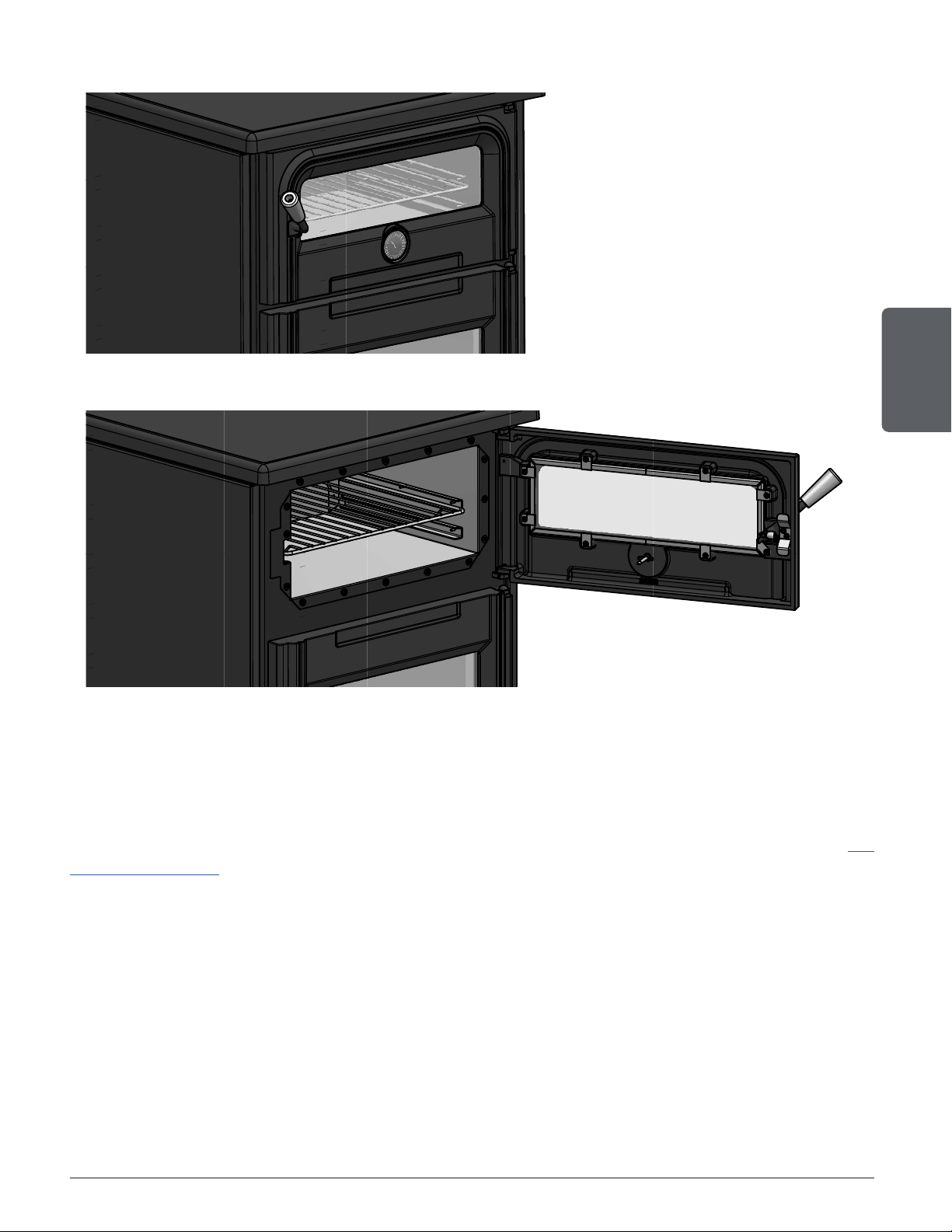
3.1.1 Oven
FIGURE 5
FIGURE 6
Figure 8: Oven door closed
FIGURE 5
FIGURE 6
Figure 9: Oven door open
The cooker has a stainless steel oven to cook or bake food. The panoramic glass of the oven
door allows you to watch your meal without having to open the door. During cooking, keep the
oven door closed to maintain a constant temperature.
The oven cooking temperature can be adjusted using the air intake control (see section "5.6
Air Intake Control") or by opening or closing the oven door. For even cooking, turn the kitchen
accessory used (plate, frying pan, dish, etc.) by 180 ° et half the cooking time.
A cooking grid is supplied with the cooker, allowing food to be cooked at center or bottom of
the oven.
The thermometer integrated in the oven door simplifies the temperature reading. The dial can
indicate temperatures ranging from 150°F to 750°F (Approximately 50°C to 400°C).
The ambient air inside the oven can vary by approximately 50°F between the hottest point and
the coldest point. Typically, the coldest spot is at the front left of the oven, near the doorknob,
and the hottest spot is at the rear right, completely opposite. The oven wall temperature is not
necessarily equal to room temperature. The thermometer indicates the ambient temperature at
a specific point in the oven, which is why the temperature indicated by the thermometer is for
reference only.

Page 14
Installation and operation manual - Bistro woodburning cookstove
ENGLISH
3.1.2 Cast iron cooking surface
FIGURE 7
Figure 10: Cast iron cooking surface
It is not recommended to cook food directly on the cast iron top, as the paint used is
not food grade.
The cast iron cooking surface on the top of the range is designed to provide intense heat to allow
food to be cooked. It was designed to cook with kitchen accessories (frying pan, saucepan,
etc.). It is recommended to use heat resistant cast iron or aluminum accessories for best results.
The temperature of the cooking surface is not necessarily uniform.
The temperature of Cast iron top cooking can be adjusted with the air intake control.
To reduce the discomfort due to the heat coming from the combustion chamber, it is recommended
to cook on the side of the appliance.
Page 15
Installation and operation manual - Bistro woodburning cookstove
ENGLISH
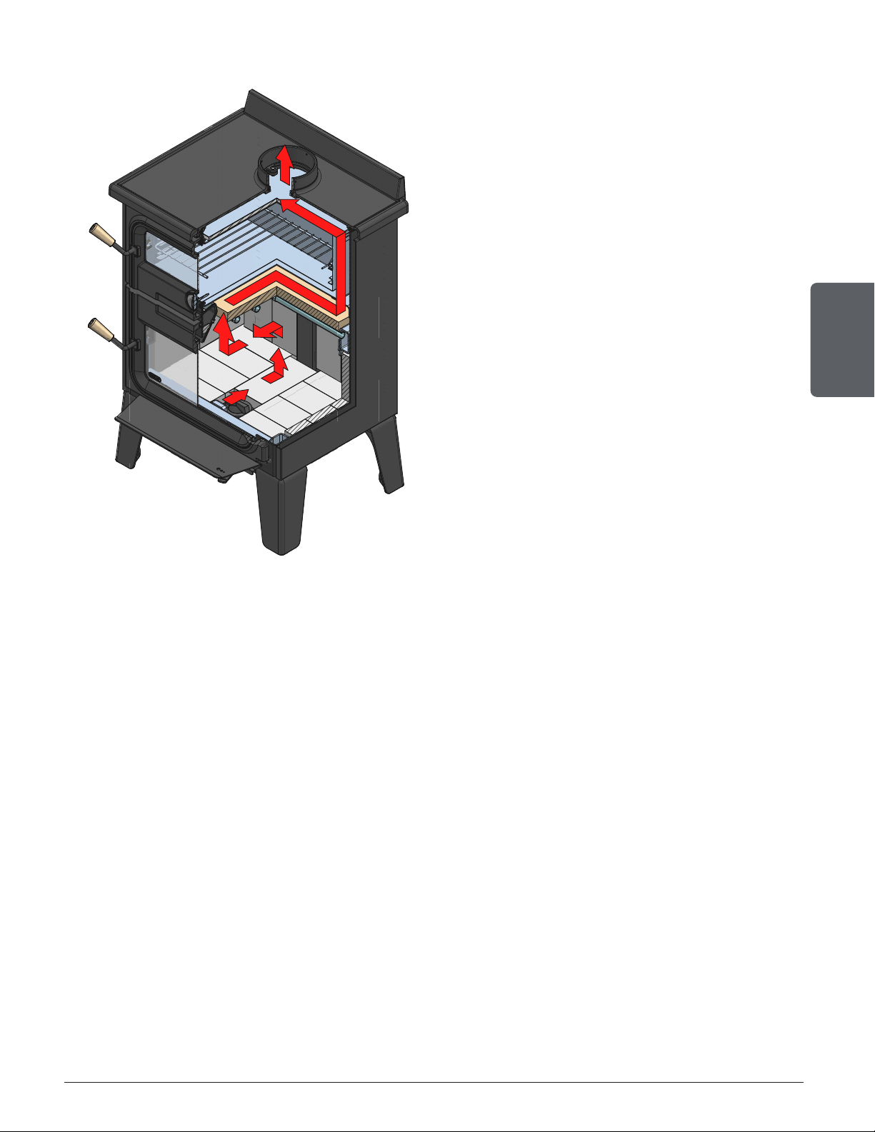
3.2 Gas path
FIGURE 8
Figure 11: Gas path
The gas path is in fact the circuit followed by the hot gases emitted by burning wood. This circuit
is used to heat the stainless steel oven and the cast iron cooking surface.
1. The primary air supply provided by the pilot feeds the wood combustion.
2. Wood burning in the combustion chamber gives off particles and hot gases heading upwards.
3. The secondary air supply from the tubes at the top of the combustion chamber burns a second
time gases and particles. This process makes the combustion cleaner and allows to regulate the
efficiency of the fire.
4. The gases burned twice are then guided by the baffle towards the front of the combustion chamber.
5. The gases then divide in two, passing through the ducts to the left and right of the oven and
joining between the oven and the cooking surface. This portion of the journey is the one that
allows for gases to transmit their heat to the oven and to the cooking surface. The path borrowed
by gases has an impact on heat distribution. For example, if the fire is further to the left in the
combustion chamber, the heat released may pass more through the ducts to the left of the device.
The temperature of the cast iron cooking surface may therefore vary according to the path taken
by the gases. On the other hand, the oven tends to keep a relatively uniform temperature thanks
to its insulation.
6. The gases finally escape through the chimney.

Page 16
Installation and operation manual - Bistro woodburning cookstove
ENGLISH
4. Combustibles
Good firewood has been cut to the correct length for the stove, split to a range of sizes and
stacked in the open until its moisture content is down to 15% to 20%.
DO NOT BURN:
• GARBAGE;
• LAWN CLIPPINGS OR YARD WASTE;
• MATERIALS CONTAINING RUBBER, INCLUDING TIRES;
• MATERIALS CONTAINING PLASTIC;
•
WASTE PETROLEUM PRODUCTS, PAINTS OR PAINT THINNERS, OR ASPHALT
PRODUCTS;
• MATERIALS CONTAINING ASBESTOS;
• CONSTRUCTION OR DEMOLITION DEBRIS;
• RAILROAD TIES OR PRESSURE-TREATED WOOD;
• MANURE OR ANIMAL REMAINS;
•
SALT WATER DRIFTWOOD OR OTHER PREVIOUSLY SALT WATER SATURATED
MATERIALS;
• UNSEASONED WOOD; OR
•
PAPER PRODUCTS, CARDBOARD, PLYWOOD, OR PARTICLE BOARD. THE
PROHIBITION AGAINST BURNING THESE MATERIALS DOES NOT PROHIBIT
THE USE OF FIRE STARTERS MADE FROM PAPER, CARDBOARD, SAW DUST,
WAX AND SIMILAR SUBSTANCES FOR THE PURPOSE OF STARTING A FIRE
IN AN AFFECTED WOOD HEATER.
•
BURNING THESE MATERIALS MAY RESULT IN THE RELEASE OF TOXIC FUMES
OR RENDER THE HEATER INEFFECTIVE AND CAUSE SMOKE.
4.1 Tree Species
The tree species the firewood is produced from is less important than its moisture content. The
main difference in firewood from various tree species is the density of the wood. Hardwoods are
denser than softwoods.
Note that hardwood trees like oak, maple, ash and beech are slower growing and longer lived
than softer woods like poplar and birch. That makes hardwood trees more valuable. The advice
that only hardwoods are good to burn is outdated. Old, leaky cast iron stoves wouldn’t hold a
fire over e longer period of time unless they were fed large pieces of hardwood. That is no longer
true.
Page 17
Installation and operation manual - Bistro woodburning cookstove
ENGLISH
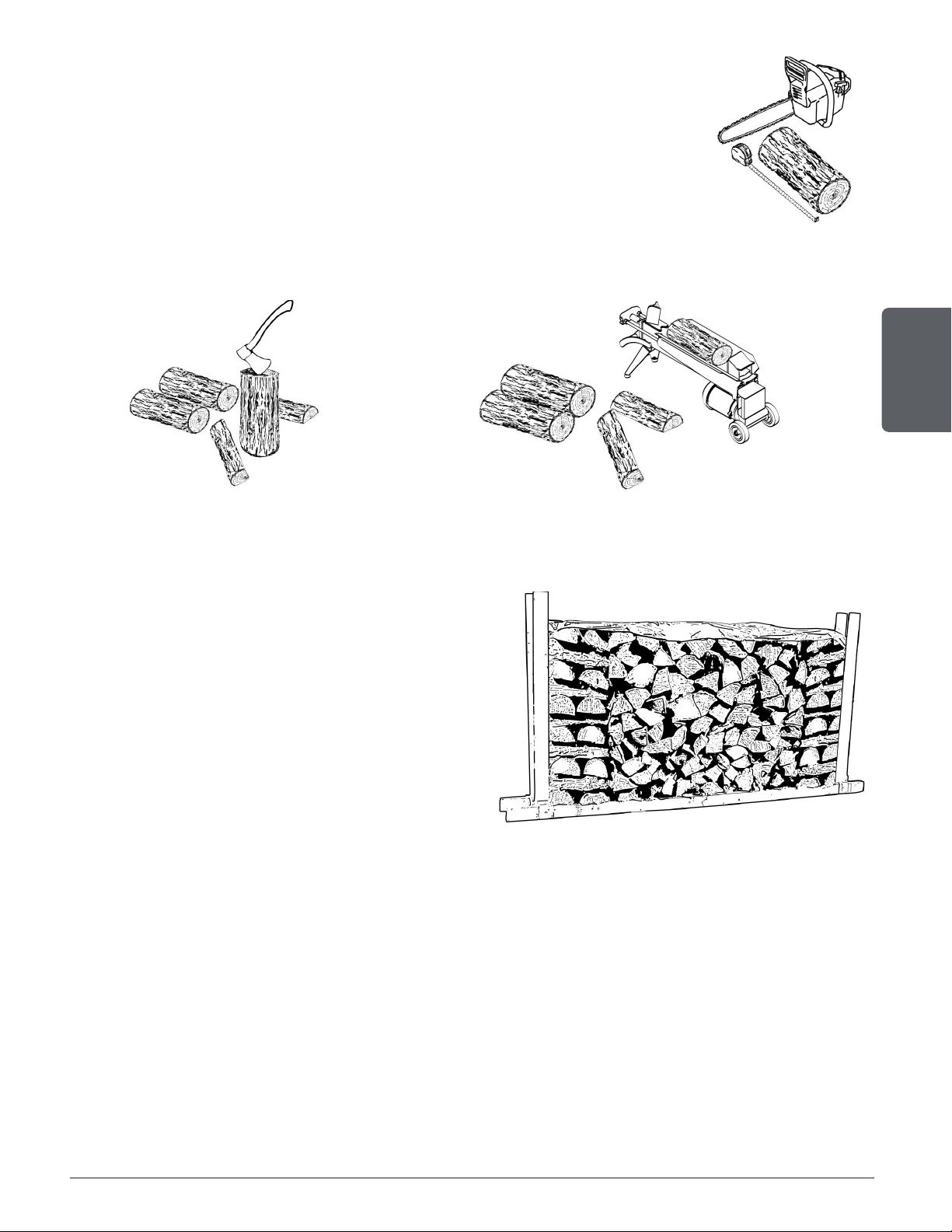
4.2 Log Length
Logs should be cut at least 1" (25 mm) shorter than the firebox so they fit in
easily. Pieces that are even slightly too long makes loading the stove very
difficult. The most common standard length of firewood is 16" (400mm).
4.3 Piece Size
Firewood dries more quickly when it is split. Large unsplit rounds can take
years to dry enough to burn. Even when dried, unsplit logs are difficult to ignite because they
don’t have the sharp edges where the flames first catch.
Wood should be split to a range of sizes, from about 3" to 6" (75 mm to 150 mm) in cross
section. Having a range of sizes makes starting and rekindling fires much easier.
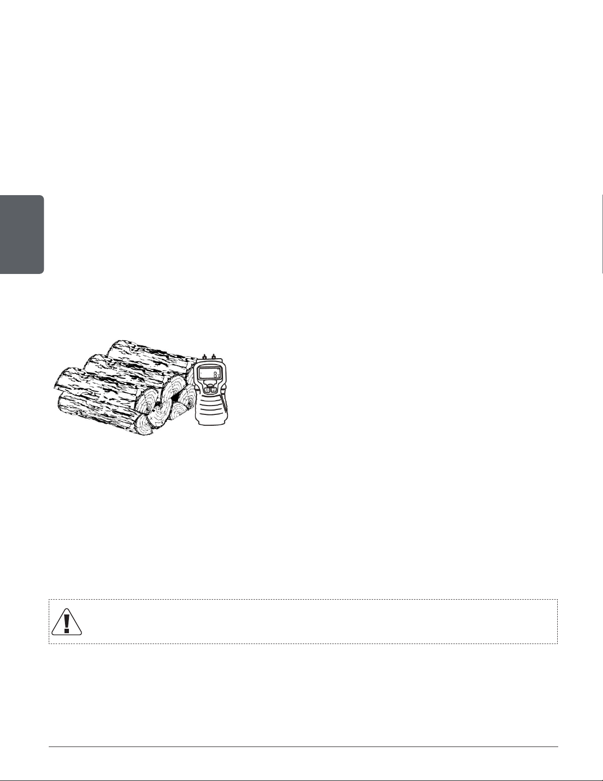
4.4 Drying Time
Firewood that is not dry enough to burn is
the cause of most complaints about wood
burning appliances. Continually burning green
or unseasoned wood produces more creosote
and involves lack of heat and dirty glass door.
Firewood with a moisture content between 15%
and 20% will allow the stove to produce its
optimal output.
Page 18
Installation and operation manual - Bistro woodburning cookstove
ENGLISH
Here are some facts to consider in estimating drying time:
− Firewood bought from a dealer is rarely dry enough to burn, so it is advisable to buy the wood in
spring and dry it yourself;
− Drying happens faster in dry weather than in a damp climate;
− Drying happens faster in warm summer weather than in winter weather;
− Small pieces dry more quickly than large pieces;
− Split pieces dry more quickly than unsplit rounds;
− Softwoods like pine, spruce, poplar, and aspen take less time to dry than hardwoods. they can be
dry enough to burn after being stacked to air dry only for the summer months;
− Hardwoods like oak, maple and ash can take one, or even two years to dry fully, especially if the
pieces are big;
− Firewood dries more quickly when stacked outside in a location exposed to sun and wind; it takes
much longer to dry when stacked in a wood shed;
− Ready-to-burn wood with a moisture content of 15% to 20% will allow the appliance to achieve
its optimal use.
Use these guidelines to find out if the firewood is dry enough to burn:
− Cracks form at the ends of logs as they dry;
− The wood turns from white or cream colored to grey or yellow;
− Two pieces of wood struck together sounds hollow;
− Dry wood is much lighter in weight than wet wood;
− The face of a fresh cut feels warm and dry;
− The moisture content read by a moisture meter is between
15% to 20%.
5. Efficient wood combustion
5.1 General Advice
Wood burns best in cycles. A cycle starts when a new load of wood is ignited by hot coals and
ends when that load has been consumed down to a bed of charcoal about the same size as it
was when the wood was loaded. Trying to produce a steady fire by placing a single log at regular
intervals is not recommended. Always place at least three, and preferably more pieces on the
fire at a time so that the heat radiated from one piece helps to ignite the pieces next to it.
Prolonged and continuous use at a very low rate of combustion or with very wet
wood can cause highly flammable creosote to build up in the flue.
Burning in cycles means the stove door does not need to be opened while the wood is flaming.
This is an advantage since it is preventing smoke leaking from the stove when the door is opened
as a full fire is burning. This is especially true if the chimney is on the outside wall of the house.
If the door must be open while the fire is flaming, fully open the air control for a few
minutes then open the door slowly.
Page 19
Installation and operation manual - Bistro woodburning cookstove
ENGLISH
5.2 First Use
Two things happen when burning the first few fires; the paint cures and the internal components are
conditioned. As the paint cures, some of the chemicals vaporize. The vapors are not poisonous,
but they smell bad. Fresh paint fumes can also trigger false alarms in smoke detectors. When
lighting the heater for the first few times, it may be wise to open doors and windows to ventilate
the house.
Burn two or three small fires to begin the curing and conditioning process. Then build bigger
and hotter fires until there is no longer paint smell from the stove. As hotter and hotter fires are
burned, more of the painted surfaces reach the curing temperature of the paint. The smell of
curing paint does not disappear until one or two very hot fires have been burned.
5.3 Lighting Fires
Each person cooking with wood develops its own favorite way to light fires. Regardless of the
method chosen, the goal should be to have a hot fire burning, quickly. A fire that ignites fast
produces less smoke and deposits less creosote in the chimney.
Consult the video using the following link to better visualize the ignition methods:
https://www.youtube.com/watch ?v=Y7O0v-nw7QQ&ab_channel=SBI
Never use gasoline, gasoline-type lantern fuel (naphtha), fuel oil, motor oil, kerosene,
charcoal lighter fluid, or similar liquids or aerosols to start or ‘freshen up’ a fire in this
wood stove. Keep all such liquids well away from the stove while it is in use.
Here are three popular and effective ways to ignite wood fires.
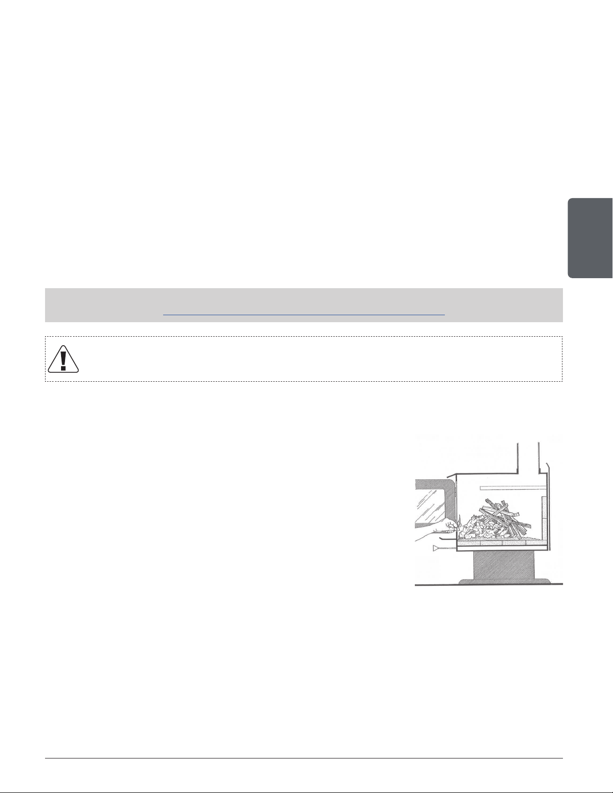
5.3.1 Conventional Method
The conventional method to build a wood fire is to crumple 5 to 10
sheets of newspaper and place them in the firebox and hold them
in place with ten pieces of kindling wood. The kindling should be
placed on and behind the newspaper.
Then add two or three small pieces of firewood. Open the air
intake control completely and ignite the newspaper. Leave the door
slightly ajar.
Once the fire has ignited, the door can be closed with the air control
still fully open. When the kindling is almost completely burned,
standard firewood pieces can be added.
Do not leave the heater unattended when the door is slightly open. Always close and
latch the door after the fire ignites.
5.3.2 The Top Down Method
This method is the opposite of the conventional method and only works properly if well-seasoned
wood is used.
Place three or four small, split, dry logs in the firebox. Arrange the kindling wood on the logs in
two layers at right angles and place a dozen finely split kindling on the second row.

Page 20
Installation and operation manual - Bistro woodburning cookstove
ENGLISH
It is possible to use ragged paper but it may not hold in place since it tends to roll while it is
burning. The best is to wrap a sheet on itself, grab the ends of the roll and make a knot. Use
four or five sheets of paper tied together and put them on top and around the kindling. Open the
air intake control completely, ignite the paper and close the door.
The top down fire method has two advantages over the traditional method: first, the fire does
not collapse on itself , and it is not necessary to add wood gradually since the combustion
chamber is full before the fire is lit.
5.3.3 Two Parallel Logs Method
Two spit logs are placed in the firebox with a few sheets of twisted newspapers in between the
logs. Fine kindling is added across the two logs and some larger kindling across those, log cabin
style. Newspaper is lit.
5.3.4 Using Fire Starters
Commercial fire starters can be used instead of a newspaper. Some of these starters are made
of sawdust and wax and others are made of specialized flammable solid chemicals. Always
follow the package directions when using. Gel starters can also be used, but only to light a fire,
in a cold combustion chamber without hot embers inside.
5.4 Combustion Cycles
Wood-burning cookstove don’t have a steady heat output. It is normal for the heat output to
increase after a new load of wood is ignited and to gradually decrease throughout the burning
cycle. This increasing and decreasing temperature can be matched with the household routines.
For example, add small pieces of wood for fast and intense cooking heat or bigger pieces for
long lasting heat to simmer a dish.
Wood burns best in cycles. A cycle starts when a new load of wood is ignited by hot coals and
ends when that load has been consumed down to a bed of charcoal about the same size as it
was when the wood was loaded.
Trying to produce a steady heat output by placing a single log on the fire at regular intervals is
not recommended. Always place at least three, and preferably more pieces on the fire at a time
so that the heat radiated from one piece helps to ignite the pieces next to it. Each load of wood
should provide several hours of heat. The size of each load may vary depending on the amount
of heat required.
Burning in cycles means the loading door does not need to be opened while the wood is flaming.
This is an advantage since it is preventing smoke leaking from the heater when the door is
opened as a full fire is burning. This is especially true if the chimney is on the outside wall of the
house.
If the door must be opened while the fire is flaming, fully open air control for a few minutes
then open the door slowly.
Page 21
Installation and operation manual - Bistro woodburning cookstove
ENGLISH
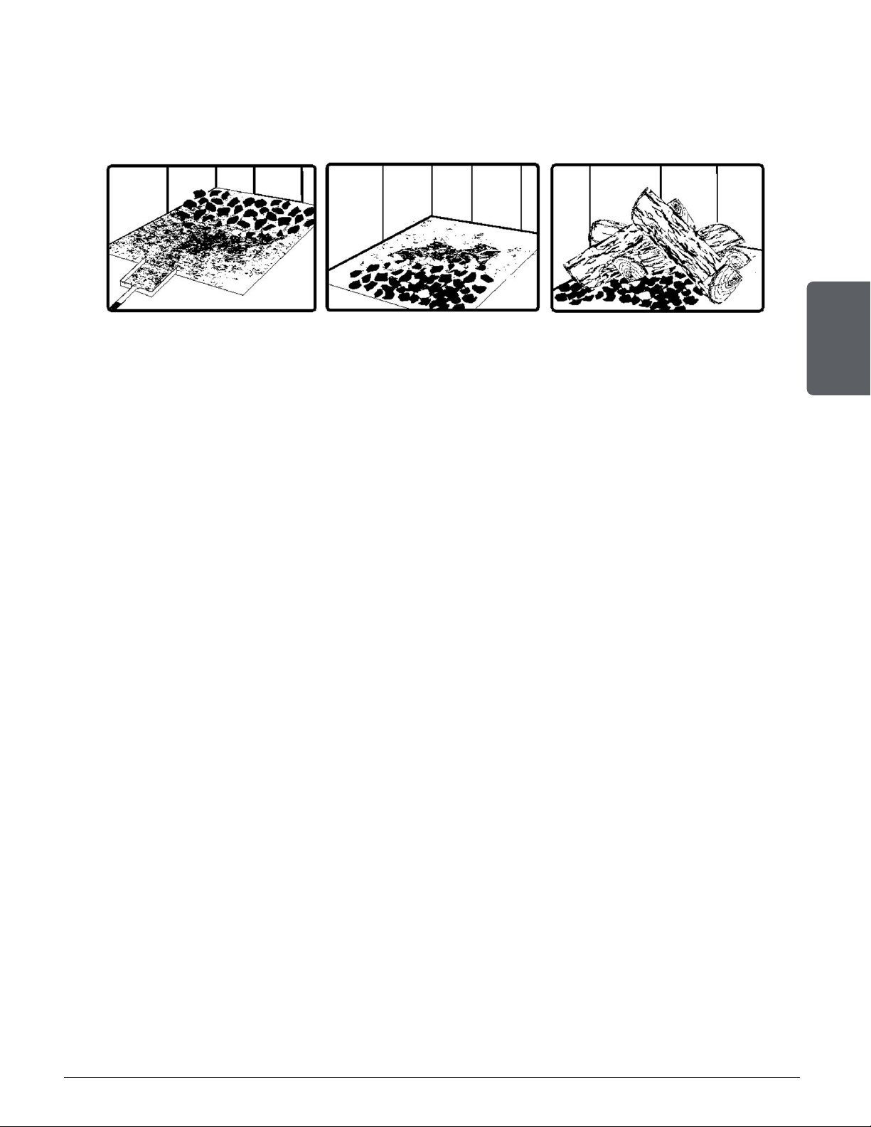
5.5 Rekindling a Fire
Generally, when you need to cook, it is time to reload. Remove excess ash from the front of
the firebox and bring the ashes forward. Place a new load of wood on, and at the back of the
embers. Open the air control completely and close the door.
Raking the coals is useful for two reasons. First, it brings them near where most of the combustion
air enters the firebox. This will ignite the new load quickly. Secondly, the charcoal will not be
smothered by the new load of wood. When the embers are simply spread inside the combustion
chamber, the new load smoulder for a long time before igniting.
Close the air control only when the firebox is full of bright turbulent flames, the wood is charred,
and its edges are glowing.
The heater should not be left unattended during ignition and the fire should not burn at full
intensity for more than a few minutes.
When lighting a new load, the appliance produces a heat surge. This heat boost is useful for
reheating the oven and cast iron cooking surface, but can give a feeling of extra heat in the room
if it is already hot there. Therefore, it is better to have a cooler room than desired to put back
a load of wood for to cook.
5.6 Air Intake Control
Once the firewood, firebox and chimney are hot, air intake can be reduced to achieve a steady
burn.
As the air intake is reduced, the burn rate decreases. This has the effect of distributing the
thermal energy of the fuel over a longer period of time. In addition, the flow rate of exhaust
through the appliance and flue pipe slows down, which increases the duration of the energy
transfer of the exhaust gases. As the air intake is reduced, the flame slows down.
If the flames diminish to the point of disappearing, the air intake has been reduced too early in
the combustion cycle or the wood used is too wet. If the wood is dry and the air control is used
properly, the flames should decrease, but remain bright and stable.
On the other hand, too much air can make the fire uncontrollable, creating very high temperatures
in the unit as well as in the chimney and seriously damaging them. A reddish glow on the unit
and on the chimney components indicates overheating. Excessive temperatures can cause a
chimney fire.
Page 22
Installation and operation manual - Bistro woodburning cookstove
ENGLISH
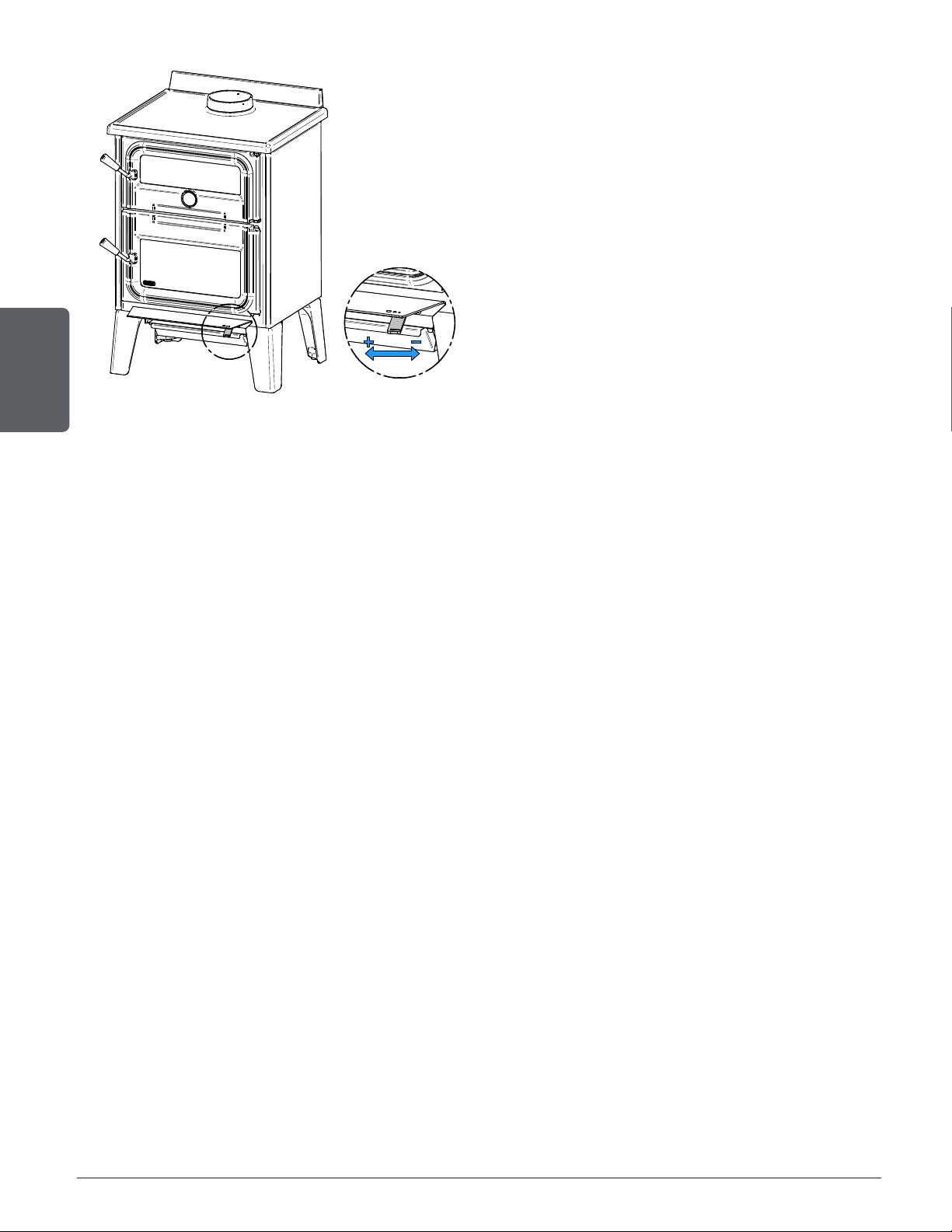
DETAIL C
DETAIL C
The control of the primary and secondary
air inlet is simultaneous and is done with a
single regulation control, located under the
combustion chamber door.
The optimum regulation of the air inlet can
vary according to various factors, such as the
chimney flue, the temperature of the cookstove
and, the quality of the firewood (moisture, size
and shape).
Do not alter the air regulation control
to increase firing for any reason.
Figure 12: Air Intake Control
5.6.1 Regulating the air during lighting
Opening the air inlet completely is mandatory during the lighting, and it is recommended to leave
the door ajar during lighting as well, in order to avoid condensation of fumes on the glass. Wait
enough time (until the hearth has warmed up) before starting to regulate the air inlet.
5.6.2 Regulating the air during combustion
Controlling the air intake is the recommended way to help adjust the temperature of the cooking
surface and one of the two recommended ways to adjust the oven temperature. Once the fire
is well established in the combustion chamber, when the flames are vivid and there is a good
bed of embers, it is possible to close the air intake. The more it will be reduced, the more the
combustion will be regulated to stretch over time. On the other hand, you need a very strong
combustion to completely shut off the air intake. It is recommended to reduce it between
15 and 40%.
5.7 Carbon Monoxide
When unburned logs remain in the firebox and the flame disappears, go outside and look at the
chimney exit. If there is visible smoke, it means that there is still combustible to burn but that
the fire lacks air to burn properly. In this situation, the CO rate will increase so it is important to
react. Open the door slightly and move the log with a poker. Turn it over and create a passage
for the air below, making a trench with the coal bed. Add small pieces of wood to restart the
combustion.

Page 23
Installation and operation manual - Bistro woodburning cookstove
ENGLISH
6. Maintenance
This cookstove will give many years of reliable service if used and maintained properly. Some of
the internal components of the firebox, such as vermiculite and baffle will wear over time under
intense heat. Defective parts should always be replaced with original parts. Firing each load
hot to begin a cycle will not cause premature deterioration of the cookstove. However, letting
the cookstove run with the air intake fully open for the entire burn cycles can cause damage
over time. The hotter the cookstove becomes throughout burn cycles, the more quickly its
components will deteriorate. For this reason, the cookstove should never be left unattended
while a new load is being fired hot.
6.1 Combustion Chamber
The cookstove cleaning frequency depends on the type and quality of combustible used. A high
humidity rate, ashes, soot, or chemical components in the wood could increase the number of
cleanings necessary. Therefore, it is important to pay attention to the combustible used.
To get the maximum performance from the cookstove, ashes should be removed regulary. The
use of a personal, central, or commercial vacuum cleaner to clean up the cookstove is not
recommended. Ash particles can damage the vacuum engine. Furthermore, hot ashes could
ignite the content of the vacuum. The use of a specialized ash vacuum is highly recommended.
6.2 Removing ashes
It is recommended to clean the ashes only when there is an accumulation that is blocking the
pilot in front of the combustion chamber or when they come out too easily when opening the
door or by putting logs. There are two ways to dispose of ashes:
1. By removing the ash plug and pushing them into the ash drawer through the opening using a
shovel.
2. By directly using a shovel in the combustion chamber and putting it in a container.
Always operate the cookstove with the ash drawer in place.
The best time to remove ashes is when the appliance is relatively cold, but there is there is still
a little draft to suck the ash dust and prevent it from entering the room. Ashes should be placed
in a metal container with a tight cover. The container should be placed on a non-combustible
floor or on the ground away from any flammable material. Ashes can contain hot embers that
can stay hot for several days. If the ashes are burried in the ground or scattered on site, they
should be kept in the closed metal container until they are completely cooled. No other waste
should be placed in this container.
CENDRES
ASHES
NEVER STORE ASHES INDOORS OR IN A NON-METALLIC CONTAINER OR
ON A WOODEN DECK.

Page 24
Installation and operation manual - Bistro woodburning cookstove
ENGLISH
6.3 Grills and cast iron cooking surface
Clean the grills with a brush and mild soap.
To clean the cast iron cooking surface, wipe it with a soft and damp cloth. Do not clean the
surface when it is hot. If rust or scratches appear, follow the instructions in section 6.4
Cleaning and painting to repair the surface.
6.4 Cleaning and Painting
Painted surfaces can be wiped down with a soft, damp cloth. If the paint is scratched or
damaged, it is possible to repaint the heater with a heat-resistant paint. Do not clean or
paint the appliance when it is hot. Before painting, the surface should be sanded lightly with
sandpaper and then wiped off to remove dust. Apply two thin layers of paint.
6.5 Refractory Materials and Baffle
Inspect the firebricks or the refractory panels and the baffle for damage periodically and replace
anything that is broken.
Operation of the heater with a cracked or missing baffle may cause unsafe temperatures
and hazardous conditions and will void the warranty.
Page 25
Installation and operation manual - Bistro woodburning cookstove
ENGLISH
6.6 Glasses
The cookstove has two glasses to maintain. The combustion chamber glass has a gasket while
the furnace does not.
6.6.1 Cleaning
Under normal conditions, the door glass should stay relatively clear. If the firewood is dry enough and the
operating instructions in this guide are followed, a whitish, dusty deposit will form on the inner surface
of the glass after a week or so of use. This is normal and can be easily removed when the heater is cold
by wiping with a damp cloth or paper towel and then drying.
When the stove runs at a low combustion rate, light brown stains may form, especially in the lower
corners of the glass. This indicates that the fire has been smoky and some of the smoke has condensed
on the glass. It also indicates incomplete combustion of the wood, which also means more smoke
emissions and faster formation of creosote in the chimney.
The deposits that form on the glass are the best indication of the fuel quality and success in properly
using the stove. These stains can be cleaned with a special wood stove glass cleaner. Do not use
abrasive products to clean the glass.
The goal should be having a clear glass with no brown stains. If brown stains appear regularly on the
glass, something about the fuel or the operating procedure needs to be changed. When brown streaks
are coming from the edge of the glass, it is time to replace the gasket around the glass.
The glass gasket should be self-adhesive. Always replace the gasket with a genuine one.
Do not clean the glass when the stove is hot.
Do not abuse the glass door by striking or slamming shut.
Do not use the stove if the glass is broken.
Page 26
Installation and operation manual - Bistro woodburning cookstove
ENGLISH
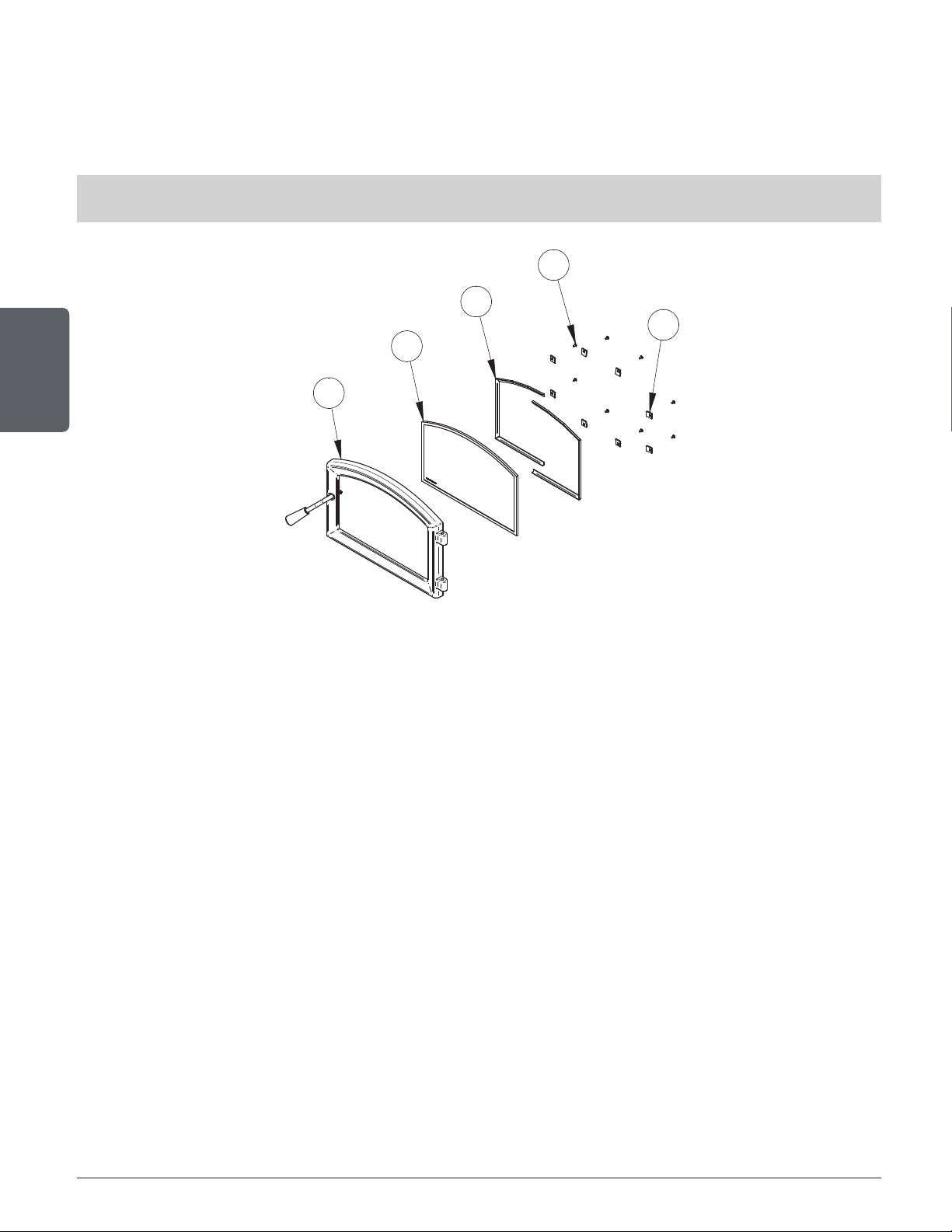
6.6.2 Replacement
The glass used is a ceramic glass, 5/32" (4 mm) thick, tested to reach temperatures up to
1400ºF. If the glass breaks, it must be replaced with one having the same specification.
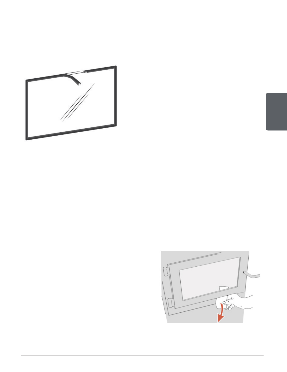
To remove or replace the glass (D):
THE IMAGES SHOWN ARE FOR GUIDANCE ONLY AND MAY BE DIFFERENT FROM YOUR PRODUCT,
BUT THE ASSEMBLY REMAINS THE SAME.
E
D
C
A
B
1. Unscrew the setscrew from the hinge at the top of the door to release the rivet (rod inserted in
the hinge). Remove the rivet while retaining the door. Lift the door (E) to remove it from the lower
hinge and place it on a soft, level surface.
2. Remove the screws (A), the glass retainers (B), and the metal frames (C).
3. Remove the glass (D). If it is damaged install a new one in place. The replacement glass must
have a gasket all around (see procedure below).
4. Reinstall the glass, being careful to centre the glass in the door and not to over-tightening the
retaining screw.
The two main causes of broken door glass are uneven placement in the door and over-
tightening the retaining screws.
Page 27
Installation and operation manual - Bistro woodburning cookstove
ENGLISH
6.6.3 Gasket
The glass gasket is flat, adhesive-backed, woven fibreglass. The gasket must be centred on the
edge of the glass.
1. Follow the steps of the previous section to remove the
glass.
2. Remove the old gasket and clean the glass thoroughly.
3. Peel back a section of the paper covering the adhesive
and place the gasket on a table with the adhesive side
up.
4. Stick the end of the gasket to the middle of one edge,
then press the edge of the glass down onto the gasket,
taking care that it is perfectly centred on the gasket.
5. Peel off more of the backing and rotate the glass. The
gasket must not be stretched during installation.
6. Cut the gasket to the required length.
7. Pinch the gasket onto the glass in a U shape, all
around the glass.
6.6.4 Replacing the Glass Door and the Glass Gasket
The glass used in the this cookstove is 4 mm thick, and was tested to reach temperatures up to
1400º F. It has the following dimensions:
− Oven (W x H): 17.5" x 5.375" (without gasket)
− Combustion chamber (W x H): 17-5/8" x 9-9/16" (with gasket)
If the glass breaks, it must be replaced with one having the same specification. Contact your
dealer to obtain a genuine replacement part.
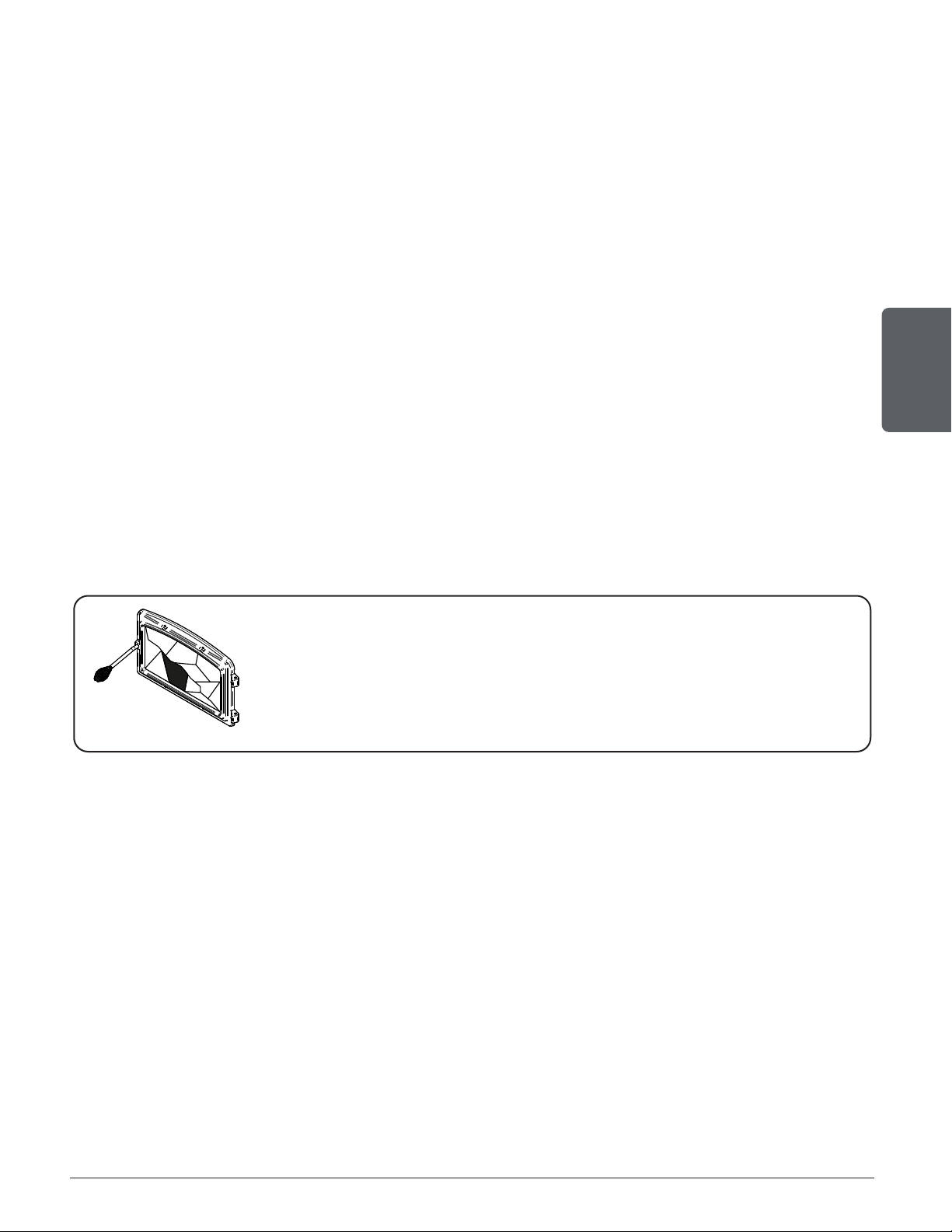
6.6.5 Door sealing
In order for the stove to bur n at its best efficiency,
the door must provide a perfect seal with the firebox.
The tightness o f the door seal can be verified by
closing and latching the door on a strip of paper.
The test must be performed all a round the door. If
the paper slips out easily anywhere, either adjust
the door or replace the gasket.
Perform this test only when the device is cold.
Page 28
Installation and operation manual - Bistro woodburning cookstove
ENGLISH
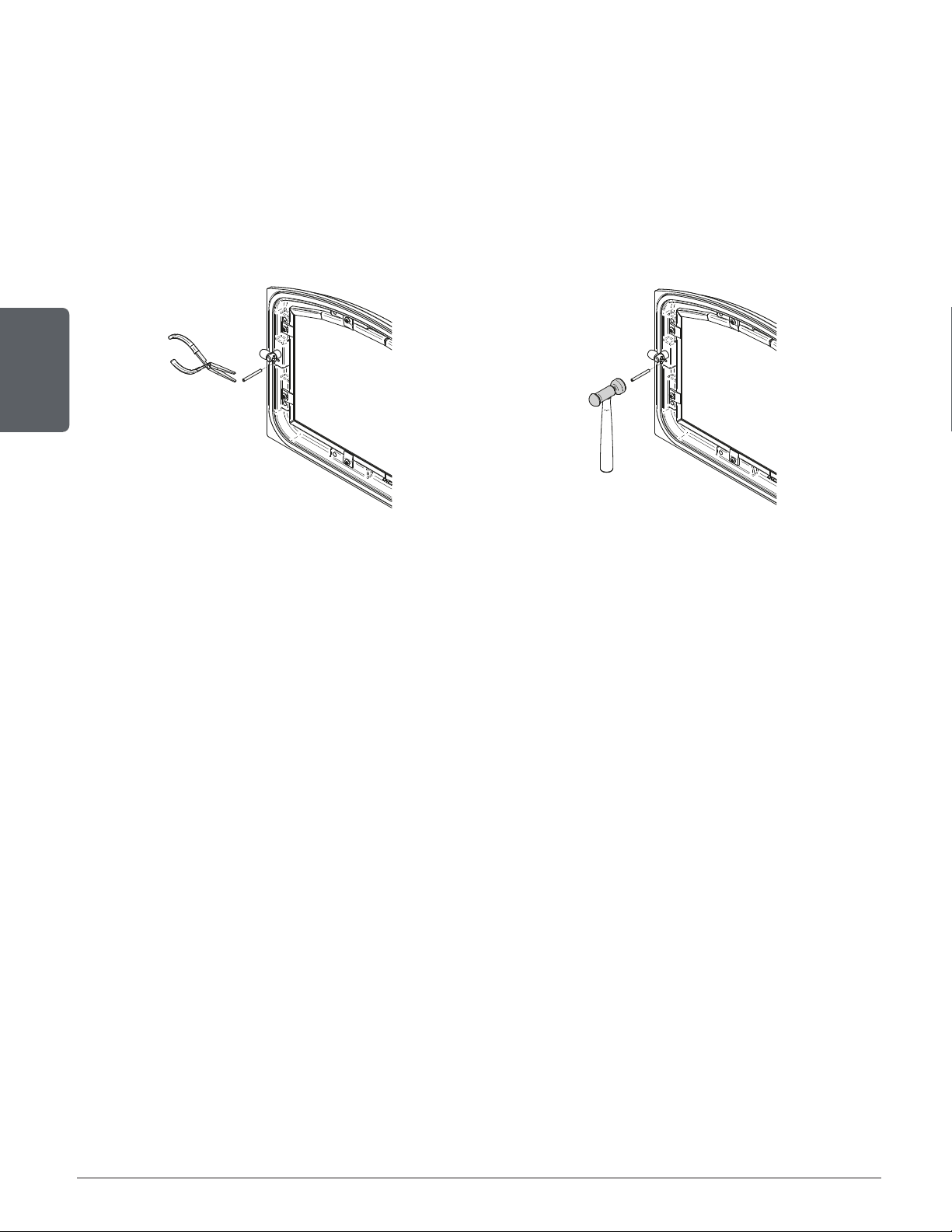
6.6.6 Adjustment of the combustion chamber door
In order for the stove to burn at its best efficiency, the door must provide a perfect seal with the
firebox. Therefore, the gasket should be inspected periodically to check for a good seal. The
gasket seal may be improved with a simple latch mechanism adjustment:
1. Remove the split pin by pulling and turning it using pliers.
2. Turn the handle one counterclockwise turn to increase pressure.
3. Reinstall the split pin with a small hammer.
Figure 13: Removing the split pin Figure 14: Installing the split pin
Page 29
Installation and operation manual - Bistro woodburning cookstove
ENGLISH
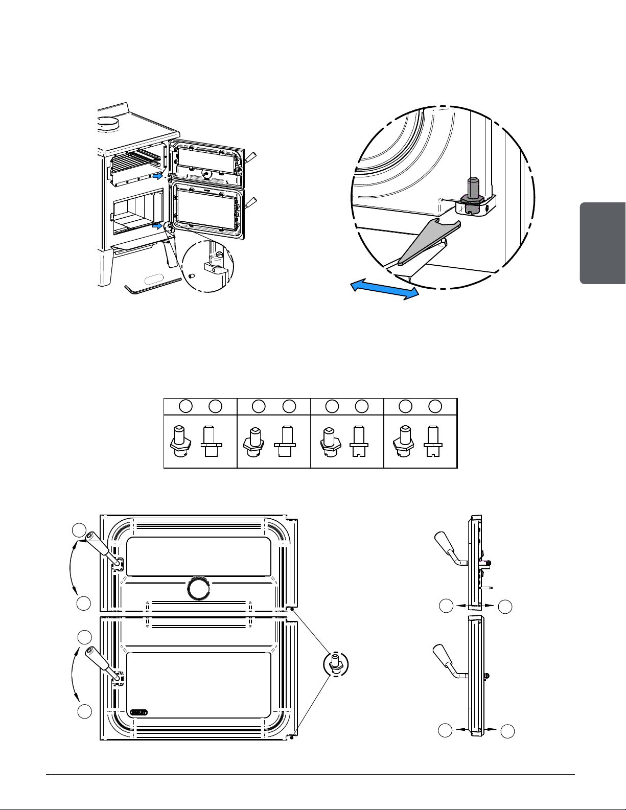
6.6.7 Door Alignment
To align, open the door and loosen the pressures screws located on the lower and upper hinges
of the door using a 3/32” Allen key to free the adjustable hinge rods.
3/32
"
1
2
4
3
5
6
7
8
3/32
"
1
2
4
3
5
6
7
8
Figure 15: Release eccentric hinges Figure 16: Adjust eccentric hinges
Using a flat screwdriver, turn the adjustable hinge rods in the direction shown to adjust the doors.
Tighten all door hinge pressure screws when they are at the desired positions. Configurations
1-2-3-4-5-6-7-8, show in which direction these act on the adjustment of the door.
1 - 3 2 - 4 5 - 7 6 - 8
Figure 17: Eccentric hinges depth adjustment
3/32
"
1
2
4
3
5
6
7
8
3/32
"
1
2
4
3
5
6
7
8
Figure 18: Doors adjustment Figure 19: Eccentric hinges lateral adjustment
Page 30
Installation and operation manual - Bistro woodburning cookstove
ENGLISH
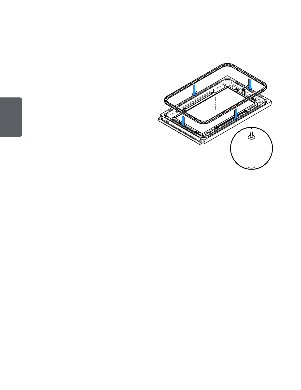
6.6.8 Gasket
It is important to replace the gasket with another having the same diameter and density to
maintain a good seal.
1. Remove the door and place it face-down on
something soft like a cushion of rags or a
piece of carpet.
2. Remove the old gasket from the door. Use a
screwdriver to scrape the old gasket adhesive
from the door gasket groove.
3. Apply a bead of approximately 3/16" (5 mm) of
high temperature silicone in the door gasket
groove. Starting from the middle, hinges side,
press the gasket into the groove. The gasket
must not be stretched during installation.
4. Leave about ½" long of the gasket when
cutting and press the end into the groove.
Tuck any loose fibers under the gasket and
into the silicone.
5. Close the door. Do not use the stove for
24hours.
FIGURE 15
Figure 20: Gasket
Page 31
Installation and operation manual - Bistro woodburning cookstove
ENGLISH
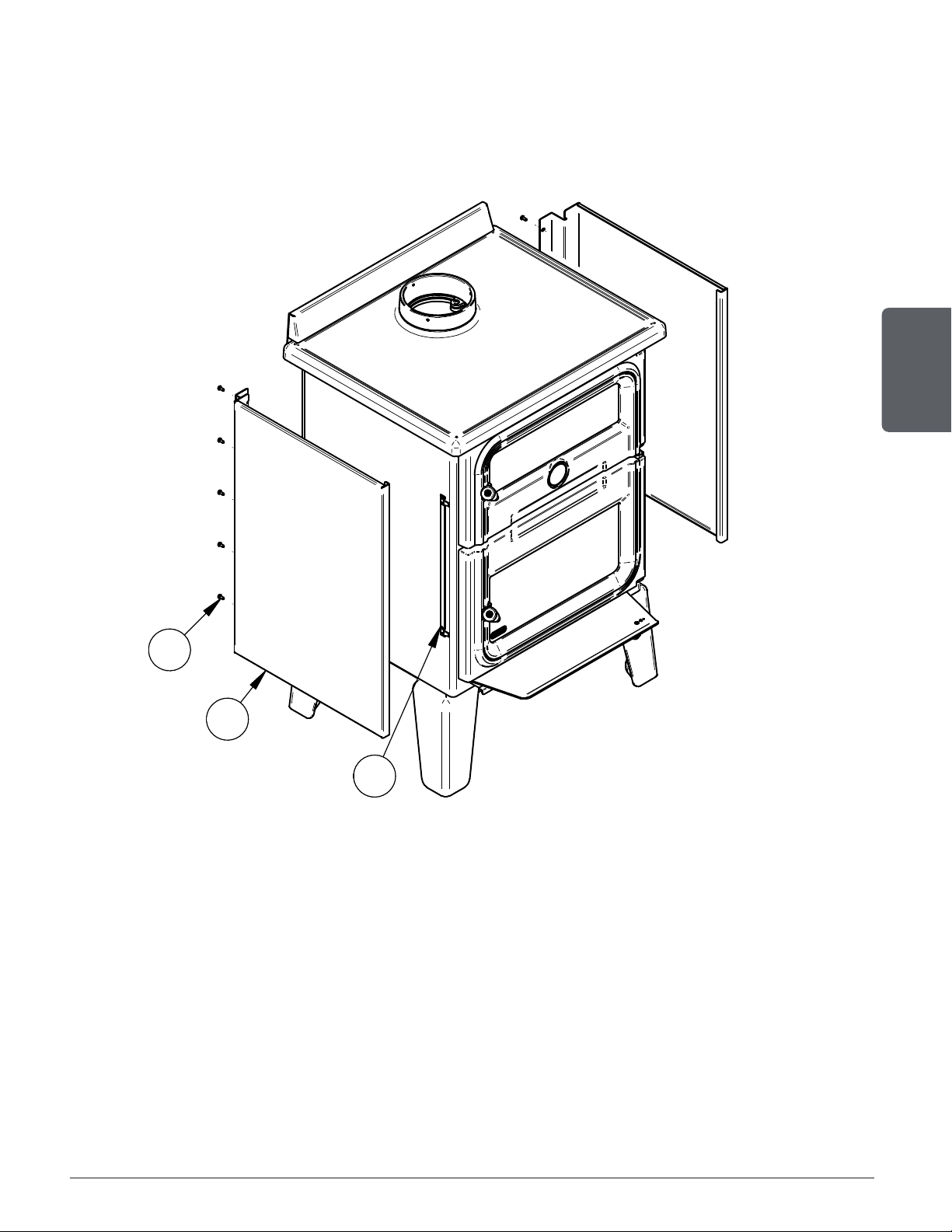
6.7 Decorative Panels
To remove the decorative panel (A), remove the screws (B) and push forward on the panel to
unhook it from the bracket (C).
A
B
C
Page 32
Installation and operation manual - Bistro woodburning cookstove
ENGLISH
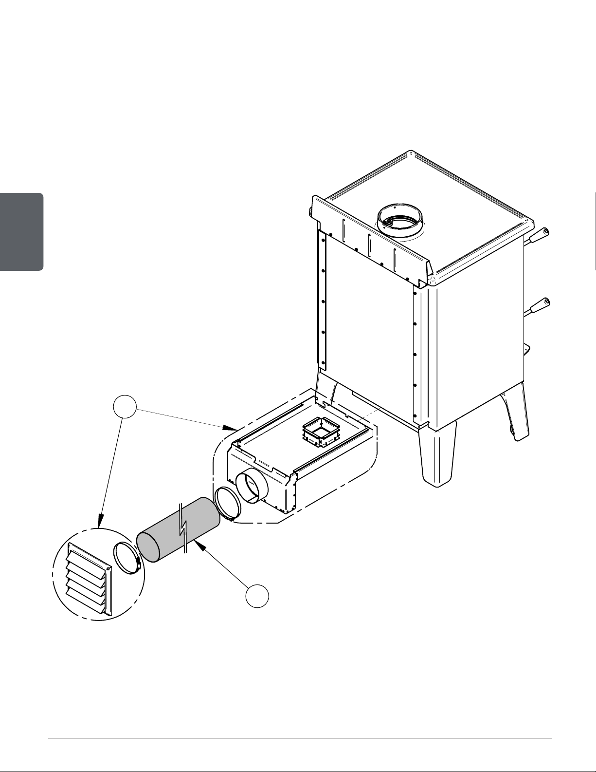
6.8 Fresh Air Intake Kit Installation
The installation of a fresh air intake kit (A) requires an insulated fresh air intake pipe (B) HVAC
type (must meet ULC S110 or UL 181 class 0 or class 1), sold separately.
It is mandatory to install the fresh air intake in a mobile home.
Refer to air intake kit installation instructions for more details.
A
B
Page 33
Installation and operation manual - Bistro woodburning cookstove
ENGLISH
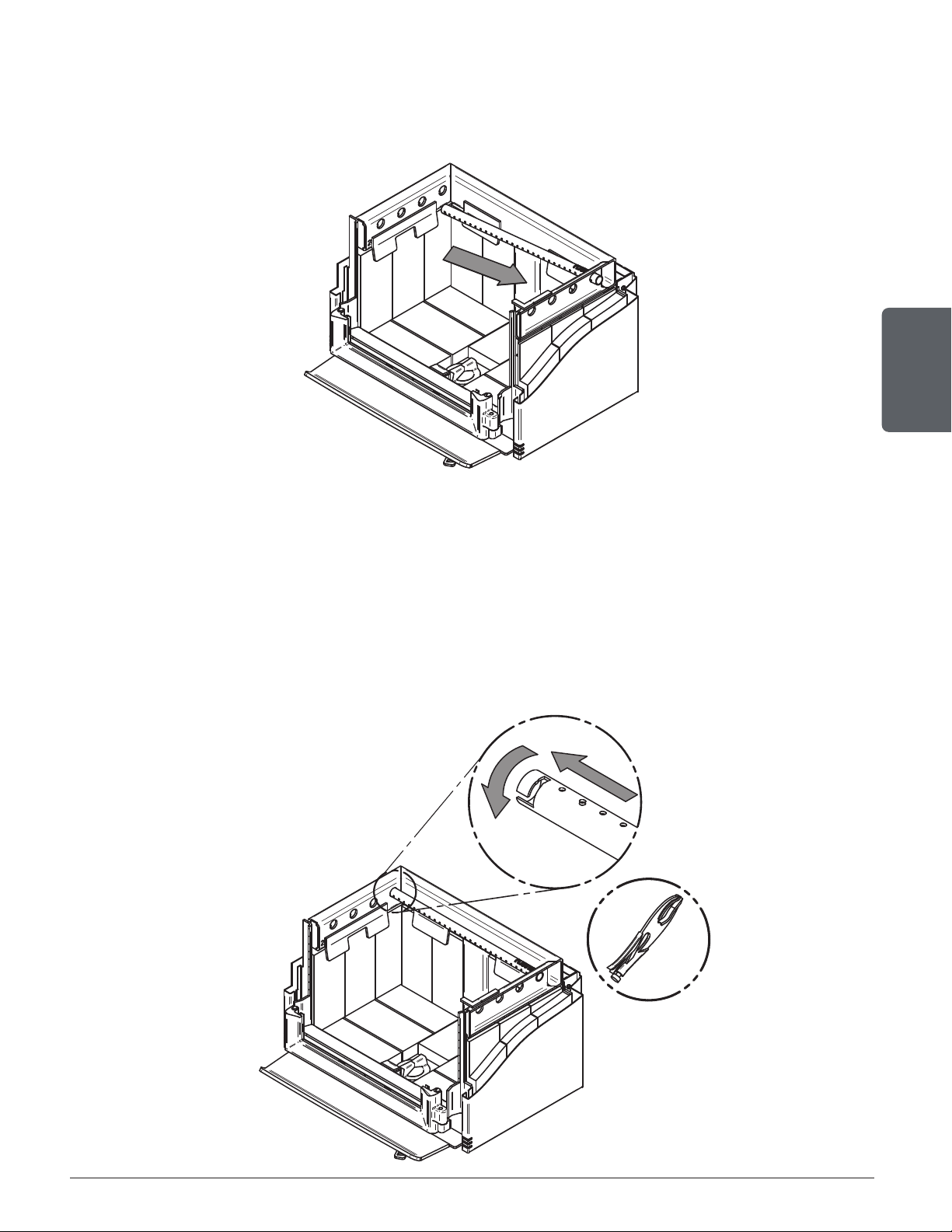
6.9 Air Tubes And Baffle Installation
1. Starting with the rear tube, lean and insert the right end of the secondary air tube into the rear
right channel hole. Then lift and insert the left end of the tube into the rear left channel.
2. Align the notch in the left end of the tube with the key of the left air channel hole. Using a « Wise
grip » hold the tube and lock it in place by turning the tube as shown. Make sure the notch
reaches the end of the key way.
3. Put the baffle in place.
4. Repeat steps 1 and 2 for the three other tubes.
5. To remove the tubes use the above steps in reverse order.
Page 34
Installation and operation manual - Bistro woodburning cookstove
ENGLISH
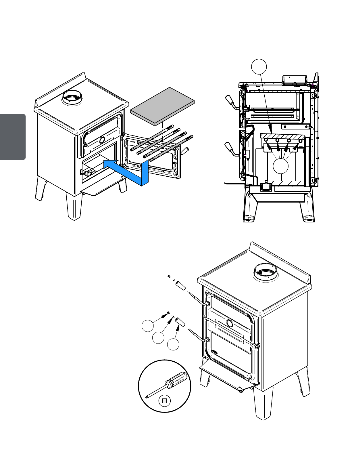
Note that secondary air tubes (B) can be replaced without removing the baffle board (A) and
that all tubes are not necessarely identical (look at the part number on the tube).
6.10 Handles installation
Insert, in order, the natural wood
handle (A), the washer (B) and
the screw (C) on the handle rod
of each door. Screw everything
in place with a square head
screwdriver.
A
B
A
B
A
B
C
Page 35
Installation and operation manual - Bistro woodburning cookstove
ENGLISH
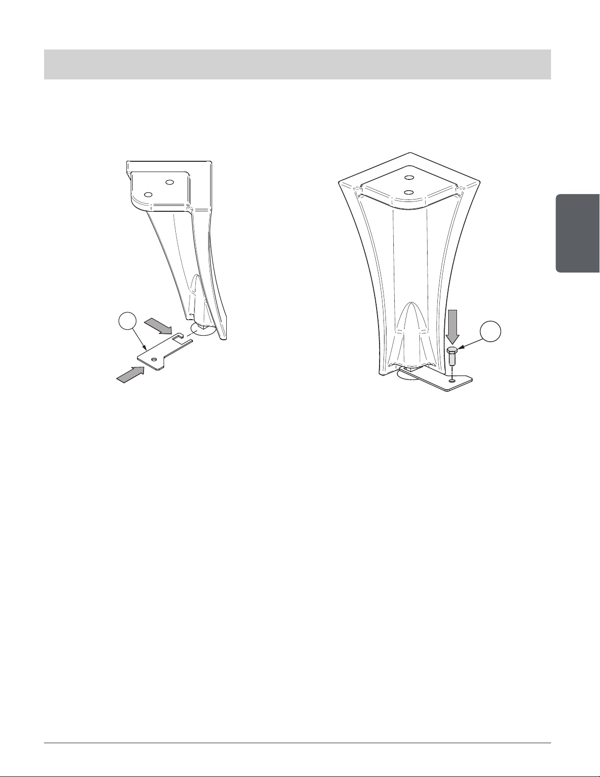
6.11 Mobile Home Installation
THE IMAGES SHOWN ARE FOR GUIDANCE ONLY AND MAY BE DIFFERENT FROM YOUR PRODUCT,
BUT THE ASSEMBLY REMAINS THE SAME.
For a stove on legs, install a plate (L) on each leg and screw it in place with the proper hardware
(M). Plates are included in the combustion chamber, but the proper hardware to screw the legs
in place is not included.
M
4x
L
4x
6.12 Exhaust System
Wood smoke can condense inside the chimney, forming a inflammable deposit called creosote.
If creosote builds up in the system, it can ignite when a hot fire is burned in the stove. A very
hot fire can progress to the top of the chimney. Severe chimney fires can damage even the best
chimneys. Smouldering, smoky fires can quickly cause a thick layer of creosote to form. When
the stove is operated properly, the exhaust from the chimney is mostly clear and creosote builds
up more slowly.
«Creosote - Formation and Need to Removal
When wood is burned slowly, it produces tar and other organic vapors, which combine with
expelled moisture to form creosote. The creosote vapors condense in the relatively cooler
chimney flue of a slow-burning fire. As a result, creosote residue accumulates on the flue
lining. When ignited this creosote makes an extremely hot fire.
The chimney connector and chimney should be inspected at least once every two months
during the heating season to determine if a creosote buildup has occurred. If a significant
layer of creosote has accumulated (⅛" [3 mm] or more) it should be removed to reduce the
risk of a chimney fire.»

Page 36
Installation and operation manual - Bistro woodburning cookstove
ENGLISH
6.12.1 Frequency
It is not possible to predict how much or how quickly creosote will form in the chimney. It is important,
therefore, to check the build-up in the chimney monthly until the rate of creosote formation is determined.
Even if creosote forms slowly in the system, the chimney should be cleaned and inspected at least once
each year.
Establish a routine for the fuel, wood burner and ring technique. Check daily for creosote build-up until
experience shows how often you need to clean to be safe. Be aware that the hotter the re the less creosote
is deposited, and weekly cleaning may be necessary in mild weather even though monthly cleaning may
be enough in the coldest months.
Contact your local municipal or provincial re authority for information on how to handle a chimney re.
Have a clearly understood plan to handle a chimney re.
6.12.2 Sweeping the Chimney
Chimney sweeping can be a difcult and dangerous job. People with
no chimney sweeping experience will often prefer to hire a professional
chimney sweep to inspect and clean the system for the rst time. After
seeing the cleaning process, some will choose to do it themselves. The
chimney should be checked regularly for creosote build-up.
Inspection and cleaning of the chimney, but mainly cleaning of the gas
path, can be facilitated by removing the bafe. See section «6.9 Air
Tubes And Bafe Installation»
To properly clean all the gas path, it is recommended to use the cleaning brush. To make sure you reach
all corners, especially the top and sides of the oven, it is recommended remove the chimney.
N.B. It is possible to remove the chimney after sweeping. The residues will thus all have fallen on top of the
oven. You can also remove the chimney before sweeping and make sure to put a container as airtight as
possible at the end of the chimney (where it has been unscrewed), to collect the residues that will fall
during the sweeping.

Page 37
Installation and operation manual - Bistro woodburning cookstove
ENGLISH
6.12.3 Chimney Fire
Regular chimney maintenance and inspection can prevent chimney res. If you have a chimney re, follow
these steps:
1. Close the stove door and the air intake control;
2. Alert the occupants of the house of the possible danger;
3. If you require assistance, alert the re department;
4. If possible, use a dry chemical re extinguisher, baking soda or sand to control the re. Do not use
water as it may cause a dangerous steam explosion;
Do not use the appliance again until the stove and its chimney have been inspected by
a qualified chimney sweep or a fire department inspector.

Page 38
Installation and operation manual - Bistro woodburning cookstove
ENGLISH

Page 39
Installation and operation manual - Bistro woodburning cookstove
ENGLISH
PART B - INSTALLATION
7. General Information
7.1 Security
• Read this manual completely before installing the cookstove. It is important to fully respect the
installation instructions. If the cookstove is not correctly installed, it could result in a fire, bodily
injuries or even death.
• The information given on the certification label affixed to the appliance always overrides the
information published, in any other media (owner’s manual, catalogues, flyers, magazines and web
sites).
• Mixing of appliance components from different sources or modifying components may result in
hazardous condtions. Where any such changes are planned, Stove Builder International Inc. Should
be contacted in advance.
• DO NOT CONNECT TO OR USE IN CONJUNCTION WITH ANY AIR DISTRIBUTION
DUCTWORK UNLESS SPECIFICALLY APPROVED FOR SUCH INSTALLATION.
• DO NOT CONNECT THIS UNIT TO A CHIMNEY FLUE SERVING ANOTHER APPLIANCE.
• HOT WHILE IN OPERATION, KEEP CHILDREN, CLOTHING AND FURNITURE AWAY. CONTACT
MAY CAUSE SKIN BURNS. GLOVES MAY BE NEEDED FOR THE STOVE OPERATION.
• WARNING: DO NOT INSTALL IN THE SLEEPING ROOM.
• MAY BE INSTALLED IN A MOBILE HOME:
- THE INSTALLATION REQUIRES A FRESH AIR KIT, SOLD SEPARATELY.
- THE STOVE MUST BE ATTACHED TO THE STRUCTURE OF THE MOBILE HOME.
- CAUTION: THE STRUCTURAL INTEGRITY OF THE MOBILE HOME FLOOR, WALL,
CEILING AND ROOF MUST BE MAINTAINED.
• Connect this stove only to a listed factory-built chimney for use with solid fuel or to a lined masonry
chimney conforming to local and national building codes.
• If required, a supply of combustion air shall be provided to the room.
• Do not use makeshift materials or make any compromises when installing this cookstove.
• Any modification to the device that has not been approved in writing by the approval authority
or the manufacturer violates CSA B365 (Canada) and ANSI NFPA 211 (USA) standards.

Page 40
Installation and operation manual - Bistro woodburning cookstove
ENGLISH
7.2 Regulations Governing the Installation of the Cookstove
In Canada, the CSA B365 Installation Code for Solid Fuel Burning Appliances and Equipment
is to be followed in the absence of local code requirements. In the USA, the ANSI NFPA 211
Standard for Chimneys, Fireplaces, Vents and Solid Fuel-Burning Appliances is to be followed
in the absence of local code requirements.
This cookstove must be connected to a chimney complying with the requirements for Type HT
chimneys in the Standard for Factory-Built Chimneys for Residential Type and Building Heating
Appliances, UL 103 HT and ULC S629 or to a code-approved masonry chimney with a flue liner.
7.3 Cookstove Positioning
Choose a location to avoid the chimney conflicting with floor joists, roof trusses, wall studs,
water pipes, electric wires, and that allows the least possible deviations in the chimney. The
location of the cookstove must allow enough room for its maintenance and the exhaust system.
This cookstove weighs approximately 575 lb (261 kg). To validate the installation of additional
floor joist, consult the local building code.
7.4 Location of the Certification Label
Since the information given on the certification label affixed to the appliance always overrides
the information published, in any other media (owner’s manual, catalogues, flyers, magazines
and web sites) it is important to refer to it in order to have a safe and compliant installation. In
addition, important information about the stove can be found (model, serial number, etc.). The
certification label is located on the back of the stove.
It is recommended to note the stove serial number on page 5 of this manual since it will be
needed to precisely identify the version of the appliance in the event replacement parts or
technical assistance is required. It is also recommended to register the warranty online.

Page 41
Installation and operation manual - Bistro woodburning cookstove
ENGLISH
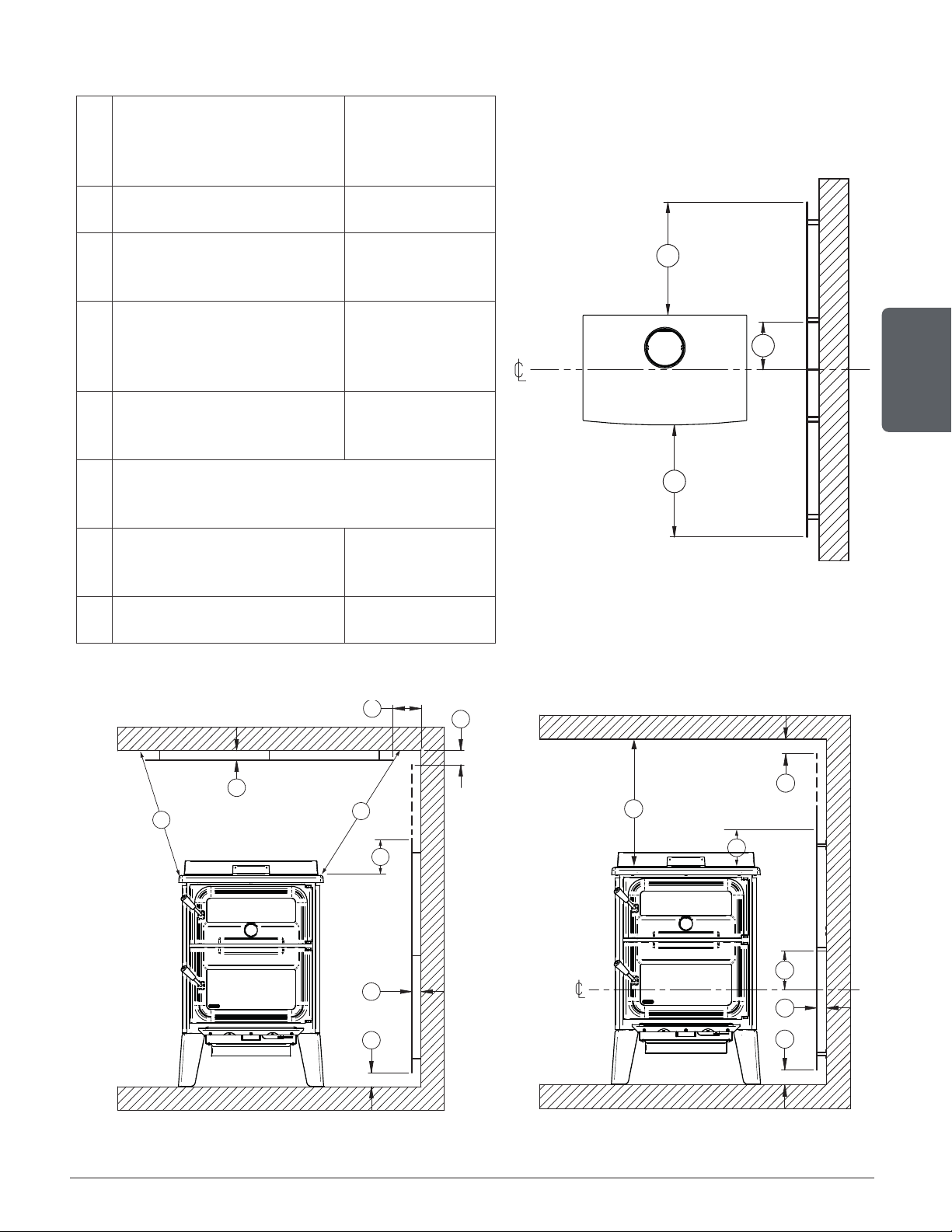
8. Clearances to Combustible Material
The clearances given in this section have been established following test results in accordance
with the procedures described in the standards ULC S627 (Canada) and UL 1482 (USA). When
this cookstove is installed respecting the indicated minimum clearances or more, the flammable
surfaces won’t overheat during normal or even abnormal usage.
None of the cookstove parts or smoke pipe can be installed closer to the combustible
materials than the minimum clearances indicated.
Fuel, solid or liquid, should not be located closer to combustibles than the minimum
clearances given.
The clearances to the combustible walls can differ slightly between Canada and the United
States and can also vary depending on the use of a single wall or double connector. Make sure
to use the proper clearances for the location and the type of pipe.
The clearances of the appliance and the flue pipes must be met individually, meaning the
appliance can not be installed closer to the combustible materials than the single or double wall
pipe allows. To know the safe way to reduce clearances,see section 8.2 Clearances Reduction
to the Walls and the Ceiling.
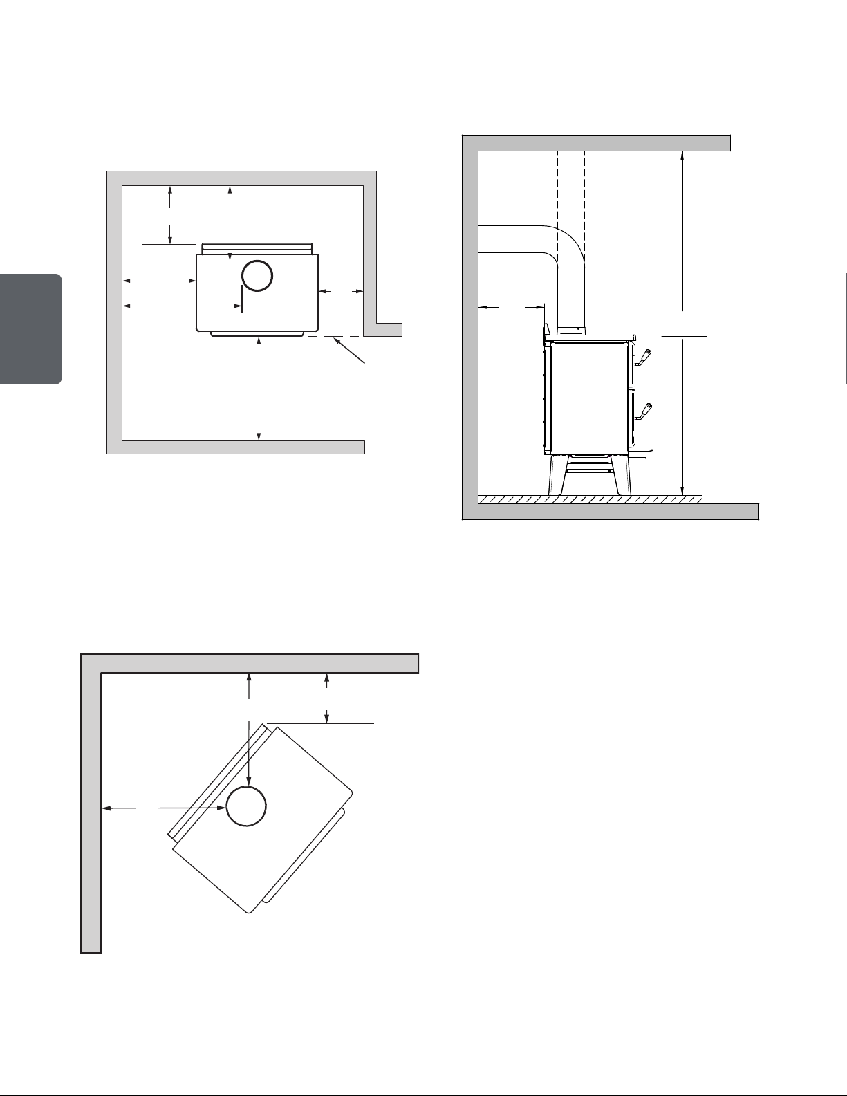
Refer to the following images and tables for minimum required clearances.
Page 42
Installation and operation manual - Bistro woodburning cookstove
ENGLISH
A
B
E
D
CAN
48"
122 cm
US
36"
92 cm
48"
Flush
N
72"
183 cm
Ho
Ve
Figure 21: Clearances - Top Figure 22: Clearances - Side
F
F
C
Figure 23: Clearances - Corner

Page 43
Installation and operation manual - Bistro woodburning cookstove
ENGLISH
APPLIANCE CLEARANCES (INSTALLATION
WITH SINGLE WALL PIPE CONNECTOR)
APPLIANCE CLEARANCES (INSTALLATION
WITH DOUBLE WALL PIPE CONNECTOR)
Canada USA Canada USA
A 15" (381 mm) 15" (381 mm) A 6" (152 mm) 6" (152 mm)
B 15" (381 mm) 15" (381 mm) B 15" (381 mm) 15" (381 mm)
C 7.5" (191 mm) 7.5" (191 mm) C 5" (127 mm) 5" (127 mm)
L 72" (183 cm) 72" (183 cm) L 72" (183 cm) 72" (183 cm)
If the above clearances are met, then the distances measured from the flue outlet will be:
DISTANCES
3
FROM PIPE CONNECTOR WITH
SINGLE WALL PIPE CONNECTOR
DISTANCES
3
FROM PIPE CONNECTOR WITH
DOUBLE WALL PIPE CONNECTOR
Canada USA Canada USA
D 18" (457 mm) 18" (457 mm) D 9" (127 mm) 9" (127 mm)
E 25" (635 mm) 25" (635 mm) E 24.75" (318 mm) 24.75" (318 mm)
F 18" (457 mm) 18" (457 mm) F 15" (318 mm) 15" (318 mm)
3
The pipe distances listed in this table refer to the distances obtained when the stove is installed in accordance with the appliance clearances
above mentioned.

Page 44
Installation and operation manual - Bistro woodburning cookstove
ENGLISH
8.1 Floor Protection
This stove is designed to prevent the floor from overheating. However, it must be placed on a
non-flammable surface to protect the floor from hot embers that may fall during loading.
Any type of tile will require a continuous non combustible sheet beneath to prevent the possibility
of embers falling through to the combustible floor if cracks or separation should occur in the
finished surface. Check local codes for approved alternatives. No protection is required if the
unit is installed on a non-combustible floor (ex: concrete).
FLOOR PROTECTION
Canada USA
G
4
8" (203 mm) N/A
H 8" (203 mm) N/A
I
18" (457 mm)
From door
opening
16" (406 mm)
From door
opening
J N/A 8" (203 mm)
K 42
7
⁄8" (1089 mm) 39
7
⁄8" (1013 mm)
N
5
N/A See note 5
S 48
3
⁄8" (1229 mm) 38
3
⁄8" (975 mm)
T 34 ¼" (870 mm) 27
1
⁄8" (689 mm)
U 42
7
⁄8" (1089 mm) 39
7
⁄8" (1013 mm)
V 69
7
⁄8" (1775 mm) 58
3
⁄8" (1483 mm)
H
I
G
J
K
S
Figure 24: Floor protection
U
T
V
N
72"
183 cm
Ho
Ve
Figure 25: Clearances Figure 26: Clearances
4
The floor protection at the back of the stove is limited to the stove’s required clearance if such clearance is smaller than 8 inches (203 mm).
5
Only required under the horizontal section (Ho) of the connector. Must exceed each side of the connector by at least 2 inches (51 mm).
Page 45
Installation and operation manual - Bistro woodburning cookstove
ENGLISH
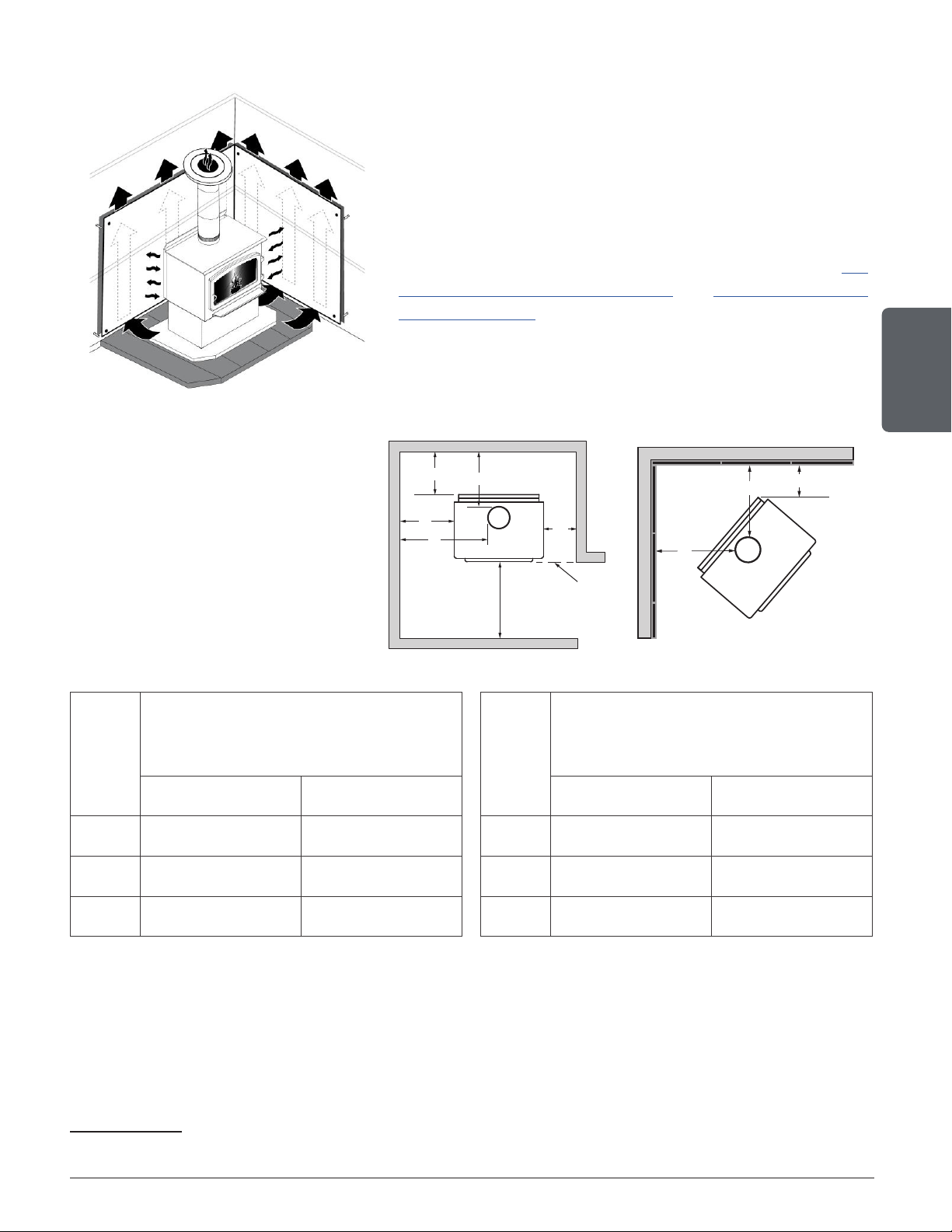
8.2 Clearances Reduction to the Walls and the Ceiling
It is often desired to use as little space as possible when
installing cookstove. To do this, it is possible to reduce
the clearances safely and install the cookstove closer
to the walls by permanently installing a heat shield
between the cookstove and the flammable material.
It is possible to obtain a heat shield that respects the
dimensions requirements indicated in sections 8.3
Clearances for Shield Installation and 8.3.2 Mobile home
with heat shield. It is possible that additional sections
or extensions are needed in order to reduce clearances
easily and safely.
It is also possible to fabricate
the heat shield but one must
be careful since the rules for
heat shield construction are
sometimes complicated. Read
and apply the instructions
carefully. Some regions may have
different regulations. Consult the
local building code or contact the
fire department for restrictions,
inspection and installation
requirements in the area.
A
B
E
D
CAN
48"
122 cm
US
36"
92 cm
48"
Flush
F
F
C
APPLIANCE CLEARANCES
WITH A SINGLE WALL PIPE CONNECTOR
AND A HEAT SHIELD
6
DISTANCE FROM PIPE CONNECTOR
WITH DOUBLE WALL PIPE CONNECTOR
AND A HEAT SHIELD
6
Canada USA Canada USA
A 2.5" (64 mm) 2.5" (64 mm) D 5.5" (140 mm) 5.5" (140 mm)
B 2.5" (64 mm) 2.5" (64 mm) E 12.25" (311 mm) 12.25" (311 mm)
C 2.5" (64 mm) 2.5" (64 mm) F 12.5" (318 mm) 12.5" (318 mm)
8.2.1 Heat Shield Construction Rules
− Adhesives used in the shield construction must not inflame or loose their adhesive properties at the
temperature that potentially will be reached.
− The assembly hardware must allow for complete vertical ventilation.
− The assembly hardware that penetrates in the combustible material from the screen surface can
only be used on the edges of the screen.
6
Note that to reduce the clearances as close as 6" from combustible material of an appliance using a single wall pipe, a certified heat shield must
be used. Only in this situation, the same clearances as with a certified double wall pipe connector can be used.
Page 46
Installation and operation manual - Bistro woodburning cookstove
ENGLISH
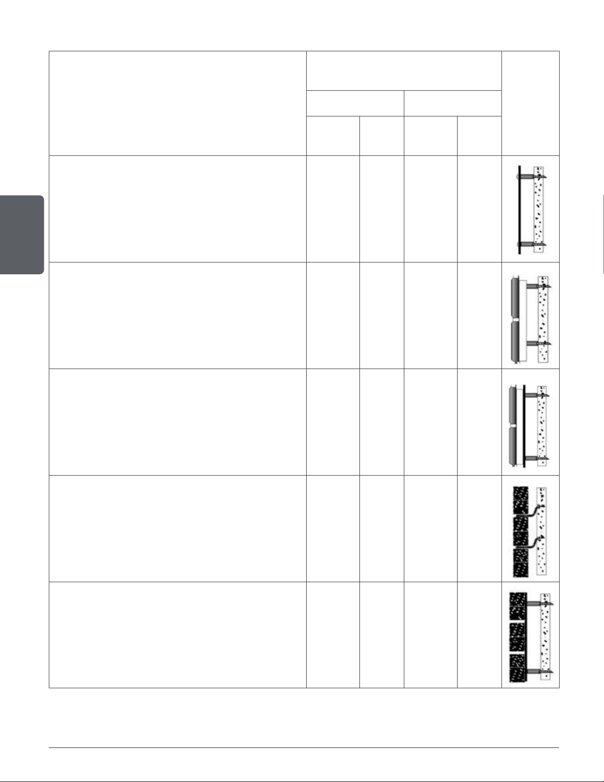
Table 1 : Clearances Reduction Percentages Table
TYPE OF SHIELD
CLEARANCES MAY BE REDUCED BY
THESE PERCENTAGES
SIDES AND REAR TOP (CEILING)
CAN /USA
(%)
USA
MIN.
CAN /USA
(%)
USA
MIN.
Sheet metal, a minimum of 24 gauge (0.61 mm)
in thickness , spaced out at least 25 mm (1 in)*
by non-combustible spacers
67 12 in 50 18 in
Ceramic tiles, or equivalent non-combustible
material, on non-combustible board spaced
out at least 25 mm (1 in)* by non-combustible
spacers
50 18 in 33 24 in
Ceramic tiles, or equivalent non-combustible
material, on non-combustible board, with a
minimum of 24 gauge (0.61 mm) sheet metal
backing spaced out at least 25 mm (1 in)* by
non-combustible spacers
67 12 in 50 24 in
Brick, spaced out at least 25 mm (1 in)* by
non-combustible spacers
50 18 in N/A N/A
Brick, with a minimum of 24 gauge (0.61 mm)
sheet metal backing, spaced out at least 25
mm (1 in)* by non-combustible spacers
67 12 in N/A N/A
* In Canada this space can be 7/8" (21 mm)
Page 47
Installation and operation manual - Bistro woodburning cookstove
ENGLISH
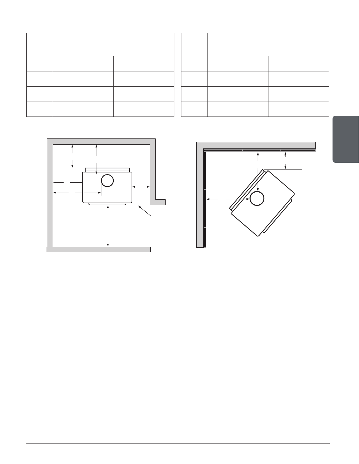
8.3 Clearances for Shield Installation
1
Minimum clearance
between the top of
the appliance and the
unprotected ceiling
833 mm
(32 13/16")
2
Shield extension above
appliance
500 mm
(20")
3
Minimum space behind the
shield
USA 25 mm (1")
Can. 21 mm
(7/8")
4
Clearance at the bottom of
the shield
USA 25 mm (1")
Can. min. 25 mm
(1") max 76 mm
(3")
5
Minimum clearance from
the top of the shield
to the ceiling:
76 mm (3")
6
The assembly hardware must not be located
at less than 200 mm (8") from the combustion
chamber central axis.
7
Shield edges clearances
from the side and back
walls for ceiling shield
75 mm (3")
8
Shield overtaking beyond
the sides of the appliance
450 mm (18")
6
8
8
Figure 27: Clearances with Heat Shield - Top
Figure 28: Clearances with Heat Shield - Face Figure 29: Clearances with Heat Shield - Face
3
4
3
7
5
1
1
2
1
4
3
5
6
2

Page 48
Installation and operation manual - Bistro woodburning cookstove
ENGLISH
8.3.1 Mobile Home
It is strictly forbidden to install a unit with a single wall pipe in a mobile home.
APPLIANCE CLEARANCES WITH DOUBLE
WALL PIPE CONNECTOR
DISTANCES
7
FROM PIPE CONNECTOR
WITH DOUBLE WALL PIPE CONNECTOR
Canada USA Canada USA
A 6" (152 mm) 6" (152 mm) D 9" (229 mm) 9" (229 mm)
B 15" (381 mm) 15" (381 mm) E 24.75" (629 mm) 24.75" (629 mm)
C 5" (127 mm) 5" (127 mm) F 15" (381 mm) 15" (381 mm)
L 84" (213 cm) 84" (213 cm)
A
B
E
D
CAN
48"
122 cm
US
36"
92 cm
48"
Flush
F
F
C
7
The pipe distances listed in this table refer to the distances obtained when the stove is installed in accordance with the appliance clearances
above mentioned.
Page 49
Installation and operation manual - Bistro woodburning cookstove
ENGLISH
8.3.2 Mobile Home With Heat Shield
APPLIANCE CLEARANCES WITH DOUBLE
WALL PIPE CONNECTOR
DISTANCES FROM PIPE CONNECTOR
WITH DOUBLE WALL PIPE CONNECTOR
Canada USA Canada USA
A 3" (76 mm) 3" (76 mm) D 6.25" (159 mm) 6.25" (159 mm)
B 3" (76 mm) 3" (76 mm) E 8.75" (222 mm) 8.75" (222 mm)
C 3" (76 mm) 3" (76 mm) F 13" (330 mm) 13" (330 mm)
A
B
E
D
CAN
48"
122 cm
US
36"
92 cm
48"
Flush
F
F
C
9. Evacuation System
9.1 General Information
The exhaust system, consisting of the chimney and the pipe that connects the cookstove to the
chimney, acts as the engine that drives the wood heating system. Even the best appliance will
not work as securely and adequately as expected if it is not connected to an adequate chimney.
The heat contained in the exhaust gas, which goes from the cookstove to the chimney connector,
then to the chimney, is not lost heat. The chimney uses that heat to create the draft that draws
the combustion air, keeps the smoke in the appliance and evacuates the gas securely toward
open air. You can consider the heat contained in the exhaust gas as the combustible that the
chimney uses to create the draft.
9.2 Suitable Chimneys
To be suitable, a prefabricated metal chimney must follow the standards UL 103 HT (USA) or
ULC S629 (Canada). Furthermore, this wood burning cookstove has a performance and optimal
efficiency when it is connected to a 6" chimney flue.
Page 50
Installation and operation manual - Bistro woodburning cookstove
ENGLISH
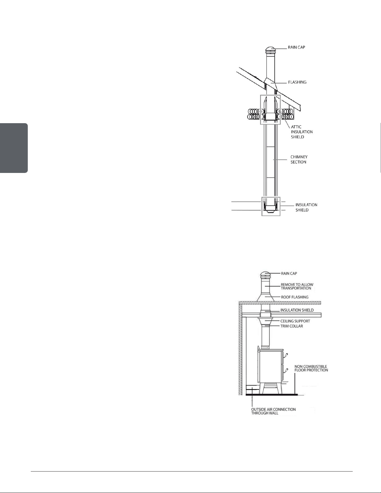
9.2.1 Factory-Built Metal Chimneys
These are sometimes referred to as ‘high
temp’ chimneys because they have the specific
characteristics to withstand temperatures that
can be created by wood burning stoves. Factory-
built chimneys are tested as a system with all
the necessary components for installation. The
instructions provided with the chimney by its
manufacturer are the only reliable source of
installation guidelines. To be safe and effective, the
chimney must be installed exactly in accordance
with the manufacturer’s instructions. Only
components intended for the brand and model
of chimney should be used. Never fabricate or
substitute parts from other chimney brands. The
chimney must be a type suitable for solid fuel.
Figure 30: Standard installation
9.2.2 Factory-Built Metal Chimneys in Mobile Homes
For use in a mobile home, this stove is to be
connected to a 6" double wall factory built chimney
pipe conforming to ULC-S629 or UL 103HT standards
for 650°C Factory-built chimney. The total length of
the flue system should be at least 12 feet including
elbows, from the top of the stove.
To maintain an effective vapour barrier, insulation
and waterproof at the chimney and outside flue pipe,
a roof flashing must be installed and sealed with
silicone adhesive.
Figure 31: Mobile home installation
Page 51
Installation and operation manual - Bistro woodburning cookstove
ENGLISH
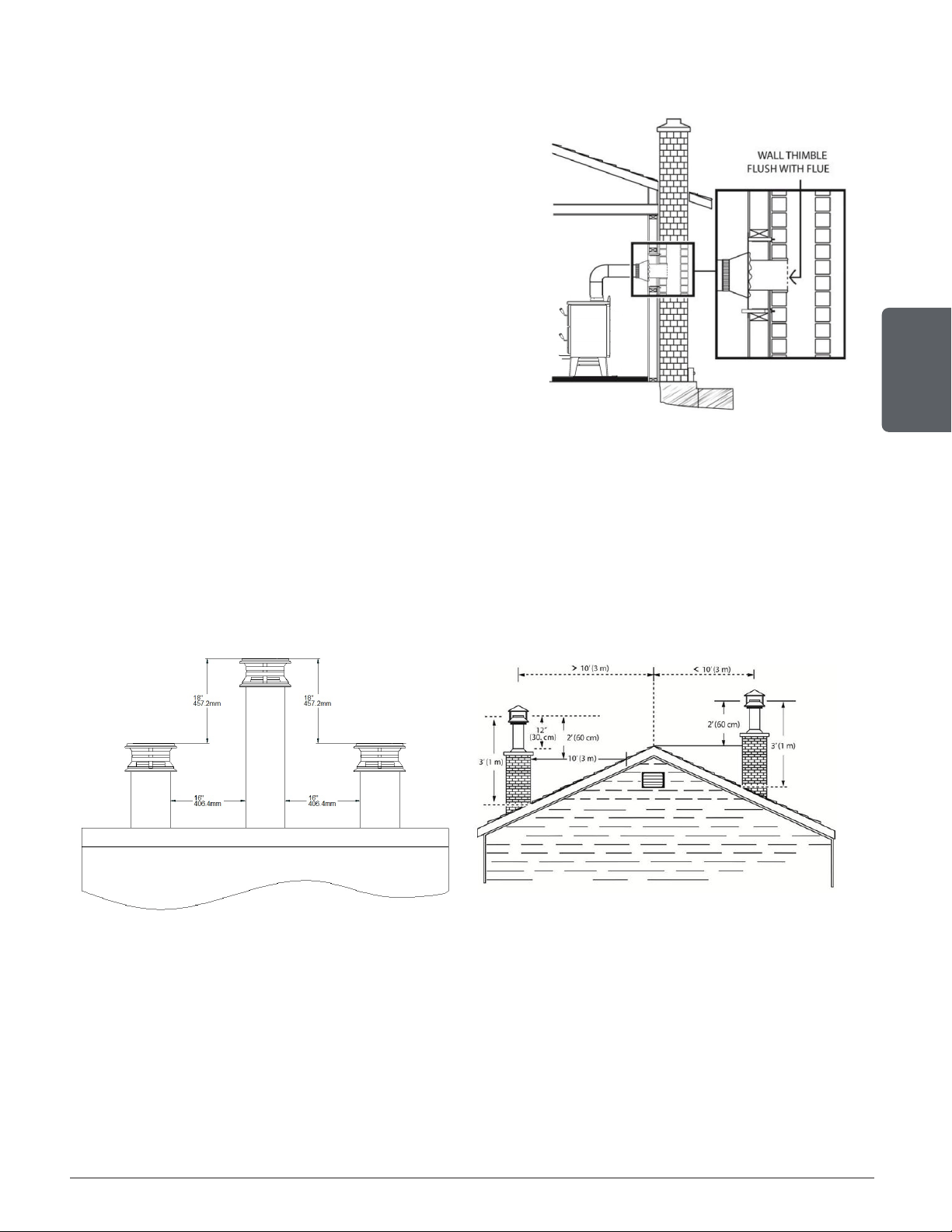
9.2.3 Masonry Chimneys
The stove may also be connected to a masonry
chimney, provided the chimney complies with the
construction rules found in the building code enforced
locally. The chimney must have either a clay liner or
a suitably listed stainless steel liner. If the masonry
chimney has a square or rectangular liner that is
larger in cross-sectional area than a round 6" flue,
it should be relined with a suitably listed 6" stainless
steel liner. Do not downsize the flue to less than 6"
unless the venting system is straight and exceeds 25
feet in height. When passing through a combustible
wall, the use of an insulated listed thimble is required.
Figure 32: Masonry hearth installation
9.3 Minimum Chimney Height
The top of the chimney should be tall enough to be above the air turbulence caused when wind blows
against the house and its roof. The chimney must extend at least 3 ft. (1 m) above the highest point of
contact with the roof, and at least 2 ft. (60 cm) higher than any roof line or obstacle within a horizontal
distance of 10 ft. (3 m).
Figure 33: Flat roof Figure 34: Sloping roof
9.4 Chimney Location
Because the venting system is the engine that drives the wood heating system, it must have the
right characteristics. The signs of bad system design are cold back drafting when there is no fire
in the stove, slow kindling of new fires, and smoke roll-out when the door is opened for loading.
There are two guidelines to follow. First, the chimney should be installed up through the heated
space of the house, not outside up on the wall. Second, the chimney should ideally go through
the highest heated space of the building or near the highest heated space.
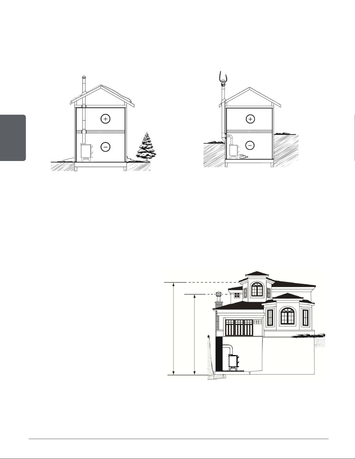
Page 52
Installation and operation manual - Bistro woodburning cookstove
ENGLISH
Venting systems that rise straight up from the stove flue collar provide the best performance. Chimneys
that rise inside the warm space of the house tend to provide a small amount of draft even when there
is no fire burning. This means that when a fire is lit, the smoke goes up the chimney and strong draft
build quickly as the chimney flue warms up. Although they are common in North America, chimneys
that exit a house wall and run up outside can cause problems.
Figure 35: Good System Design Figure 36: Acceptable System Design
When it is cold outside, the warm air in the house is buoyant so it tends to rise. This creates
a slight pressure difference in the house. Called ‘stack effect’, it produces a slightly negative
pressure in the lower part of the house (compared to the outside) and a slightly positive pressure
zone in the high part of the house. If there is no fire burning in a heater connected to a chimney
that is shorter than the warm space inside the house, the slight negative pressure in the lower
part of the house will compete against the desired upward flow in the chimney. This occurs for
the two following reasons:
First, the chimney runs up the outside of
the house, so the air in it is colder and
denser than the warm air in the house.
And second, the chimney is shorter than
the heated space of the house, meaning
the negative pressure in the lower part
of the house will draw cold air down the
chimney, through the stove and into the
room. Even the finest stove will not work
well when connected to this chimney.
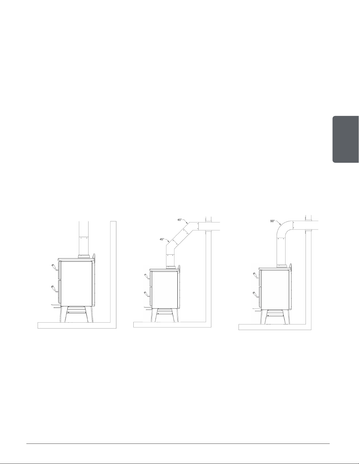
Page 53
Installation and operation manual - Bistro woodburning cookstove
ENGLISH
10. Installing the Chimney Connector
The chimney connector is the single or double wall pipe installed between the stove flue collar
and the chimney breech. Single wall pipe components are available from most hardware and
bu ilding supply stores. These components are not usually tested to a particular standard and
certified as compliant. Therefore, a list of rules found in solid fuel installation codes apply to the
installation of a single wallpipe.
Double wall chimney connectors are tested and certified. The rules for double wall pipe a
refound in the manufacturer’s installation instructions. These rules will be very different than
those for single wall.
10.1 Installation of Single Wall Chimney Connector
The chimney connector assembly has been called ‘the weak link’ in the safety of wood heating
systems because failure to install the connector properly (which has been common in the past)
can result in house fires.
The best flue pipe assembly is one that rises straight up from the stove to the base of the
chimney with no elbows. Straight assemblies are less likely to cause problems like smoke rollout
when the door is opened for loading. They are also more stable and easier to maintain than
assemblies with elbows. Horizontal runs of flue pipe should be avoided where possible because
they reduce chimney draft.
Figure 37: Best Figure 38: Acceptable Figure 39: Avoid
The rules below are based on those found in the CSA B365 installation code. Please carefully
follow these installation instruction rules, or those enforced by the local code.
• Maximum overall length of horizontal pipe: 10 ft. (3 m) including elbows.
• Minimum clearance from combustible material: 18" (450 mm). The minimum clearance may be
reduced by 50 percent to 9" (225 mm) if suitable shielding is installed either on the pipe or on the
combustible surface.

Page 54
Installation and operation manual - Bistro woodburning cookstove
ENGLISH
• The assembly should be as short and direct as possible between the stove and chimney. The use
of two 45 degree elbows is often preferable to a single 90 degree elbow because less turbulence is
created in the exhaust flow and they result in less horizontal run.
• The minimum overall height of the chimney system, measured from the stove top to the exterior
termination cap of the chimney should be at least 12 ft. (3.66 m). A chimney which is too short may
lack the “tunnel effect” required to obtain a proper draft.
• Maximum number of 90-degree elbows: 2.
• Maximum unsupported horizontal length: 3 ft. (1 m).
• Galvanized flue pipes must not be used because the coatings vaporize at high temperatures and
release dangerous gases. Use black painted flue pipes.
• Flue pipes must be at least 24 gauge in thickness.
• Flue pipe joints should overlap 1 ¼" (30 mm).
• Each joint in the assembly must be fastened with at least three screws.
• The assembly must make allowance for expansion: elbows in assemblies allow for expansion;
straight assemblies should include an inspection wrap with one end unfastened, or a telescopic
section.
• Minimum upward slope towards the chimney: ¼ in/ft. (20 mm/m).
• One end of the assembly must be securely fastened to the flue collar with 3 sheet metal screws and
the other end securely fastened to the chimney.
• There must be provision for cleaning of the pipes, either through a clean out or by removal of the
pipe assembly. Removal of the assembly should not require that the stove be moved.
• The male ends of the sections must be oriented towards the appliance so that falling dust and
condensation stay inside the pipe.
• A flue pipe must never pass through a combustible floor or ceiling or through an attic, roof space,
closet or concealed space. Where passage through a wall or partition of combustible construction
is desired, the installation shall conform to CAN/CSA-B365, Installation Code for Solid-Fuel-Burning
Appliances and Equipment.
• A straight up connector assembly needs either a telescopic length or an inspection wrap (pipe
coupler) to allow it to be assembled and disassembled without moving the stove.
• A straight flue pipe assembly offers the least restriction to gas flow and results in a stronger draft.
Straight assemblies also need less maintenance because there are no corners to collect creosote.
• The chimney connector must be clean and in good condition.
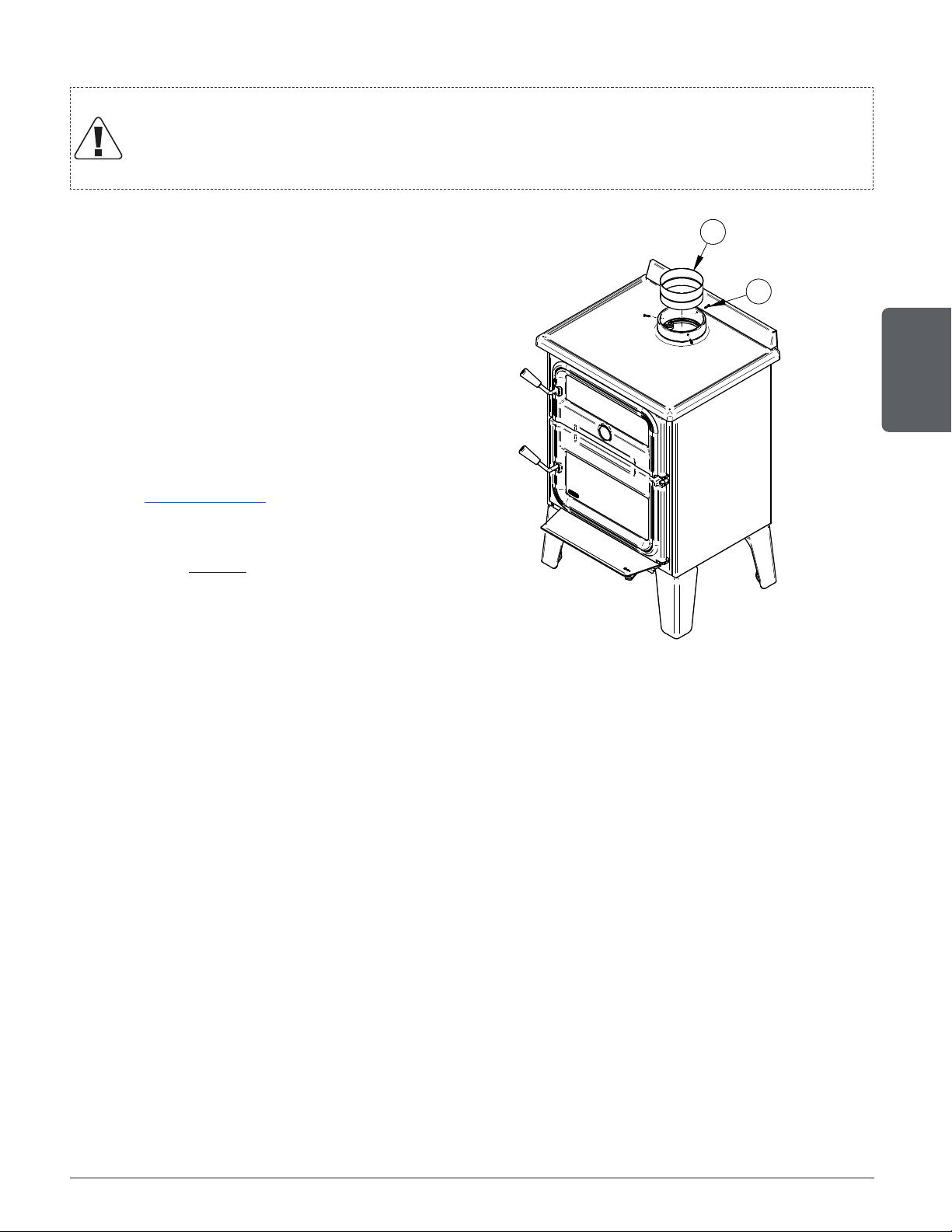
Page 55
Installation and operation manual - Bistro woodburning cookstove
ENGLISH
10.2 Installation of Double wall Chimney Connector
Important!
A double wall chimney connector can be installed only with the universal connector
PL36899 supplied with the cookstove and a vented double wall stove adaptor.
To install a double wall connector on
the appliance, the universal connector
supplied with the stove must be installed
as shown on the picture bellow.
Insert the connector (A) to the spigot and
fix it with the 3 screws (B) included with
the appliance.
A vortex double wall connector, with
its vented stove adapter (VOD0290), is
recommended for this type of installation.
Consult www.drolet.ca for more details.
Other brands of double wall connectors
are adequate as long as they offer the
option of a vented double wall stove
adapter.
A
B
Figure 40: Universal connector PL36899

Page 56
Installation and operation manual - Bistro woodburning cookstove
ENGLISH
11. Combustion Air
For the cookstove draft to work correctly, the room must have an outside or fresh air inlet, with
a minimum of 5" diameter, from the house exterior to the room, that is at least sufficient to
replenish the volume of air that comes out of the chimney flue. In well insulated houses an air
inlet must be fitted through the outer wall that is not exposed to the prevailing winds, depending
on the surrounding conditions of the house. If a vent is installed, it must be fitted in such a way
that it cannot be blocked. A fresh air intake register with a airtight damper may be installed to
help prevent any uncomfortable air draft.
When the cookstove and the chimney are completely cold, it may be necessary before starting
up to provide an external air supply by opening a door or a window for a short period. A
house constructed or renovated in a waterproof manner is prone to not having the air exchange
required for the proper functioning of a wood heating appliance.
In that case, avoid, during startups, to use appliances that evacuate air outside of the house,
such as:
• Cookstove hood
• Bathroom vent
• Air exchange system
• Ventilated central vacuum cleaner
• Dryer
The supply of fresh combustion air can be done in several ways, provided they comply with CSA
B365 and NFPA211.
In Canada, wood stoves are not required to have a combustion air supply from outside, except
for mobile homes. Research has shown that outside air supply do not compensate for the
depressurization of the house and may not be sufficient to provide a supply of combustion air in
windy weather. However, to reduce the risks against smoke spillage due to house depressurization,
a carbon monoxide (CO) detector is required in the room where the stove is installed. The CO
detector will provide warning if for any reason the wood stove fails to function correctly.
11.1 Mobile home
This stove is ‘mobile home approved’. It must therefore have a supply of combustion air from
outdoors. The air intake must not draw air from the attic, from the basement, from a garage or
any enclosed space. Air must be drawn from a ventilated crawl space under the floor or directly
from outside. Install a flexible or rigid, insulated pipe (HVAC type, must comply to ULC S110
and/or UL 181, Class 0 or Class 1) to the fresh air intake.
Where a mobile home has been converted to a standard house by mounting it on a permanent
basement foundation, the supply of outdoor air is not required.
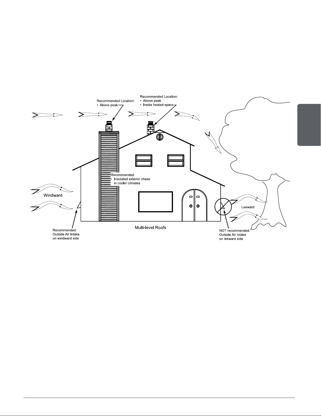
Page 57
Installation and operation manual - Bistro woodburning cookstove
ENGLISH
11.2 Conventional House
The safest and most reliable supply of combustion air for a wood stove is from the room in which
it is installed. Room air is already preheated so it will not chill the fire, and its availability is not
affected by wind pressures on the house. Contrary to commonly expressed concerns, almost
all tightly sealed new houses have enough natural leakage to provide the small amount of air
needed by the stove. The only case in which the wood stove may not have adequate access to
combustion air is if the operation of a powerful exhaust device (such as a kitchen range exhaust)
causes the pressure in the house to become negative relative to outdoors.
Figure 41: Air supply in conventional houses
If an air intake is installed through the wall of the house, its pressure can vary during windy
weather. If there are changes in wood stove performance in windy weather, and in particular if
smoke puffs from the stove, the air duct should be disconnected from the stove to determine if
it is the cause of the problem. In some windy conditions, negative pressure at the duct weather
hood outside the house wall may draw hot exhaust gases from the stove backwards through the
duct to outdoors. Check the outdoor air duct for soot deposits when the full system is cleaned
and inspected at least once each year.

Page 58
Installation and operation manual - Bistro woodburning cookstove
ENGLISH
12. Troubleshooting
PROBLEM POSSIBLE CAUSES SOLUTION
Oven window
or combustion
chamber’s window
blackening.
• Draft too low
• Bad air intake adjustment
• Too much combustible in the
cookstove.
• Wood with a high rate of
relative humidity > 20-25%
• Unregulated combustion.
• Check that all the pipes are clean.
• Modify the chimney: increase the height
or check surrondings.
• Reduce the quantity of combustible in
the combustion chamber.
• Dry the wood longer.
Irregular draw.
• Inadequate or dirty chimney.
• Dirt in the combustion
chamber or in the cookstove.
• Strong winds
• Sweep the chimney or have it clean by a
professional.
• Clean the cookstove.
• Relocate chimney or fresh air intake.
Black smoke
leaking out of the
cookstove.
• Ignition with green wood.
• Smoke pipe obstructed.
• Ignite the cookstove with suitable
combustible.
• Ask for professional qualified assistance.
Smoke coming out
of the cookstove.
• Combustion chamber’s door
open while the cookstove is
heating.
• Insufficient draw
• Bad adjustments of the air
inlets during startup.
• The cookstove must be
cleaned.
• Check the door closing and the tightness
of the gaskets.
• Check the chimney system.
• Eliminate or reduce to minimum the
deviations and horizontal lengths in the
chimney.
• Check all the chimney sections as well as
its height on the outside.
• Ask for a chimney inspection by a certified
technician.
• Regularly clean the cookstove as
indicated.
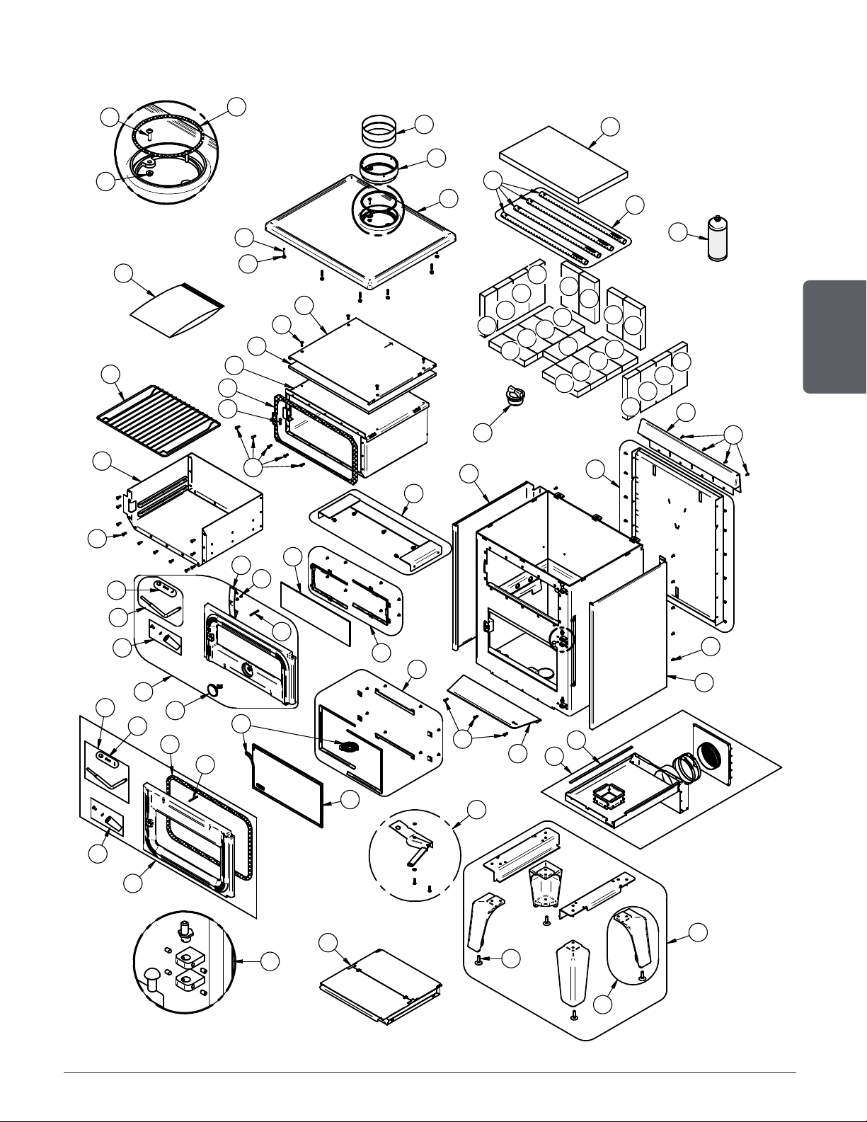
Page 59
Installation and operation manual - Bistro woodburning cookstove
ENGLISH
13. Parts List
41
40
50
49
52
51
31
22
30
36
22
35
34
44
32
33
14
39
37
38
15
3
13
12
6
11
2
4
22
1
5
6
7
8
4
3
2
17
23
25
22
9
26
45
47
47
47
45
47
47
47
45
47
47
47
45
47
47
47
46
46
47
47
46
27
28
29
27
26
18
21
C
DETAIL C
16
20
*
48
24
10
19
E
DETAIL E
43
42
37
33
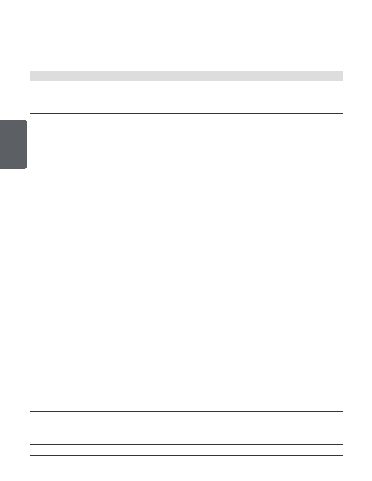
Page 60
Installation and operation manual - Bistro woodburning cookstove
ENGLISH
IMPORTANT: THIS IS DATED INFORMATION. When requesting service or replacement parts
for your unit, please provide the model number and the serial number. We reserve the right to
change parts due to technology upgrade or availability. Contact an authorized dealer to obtain
any of these parts. Never use substitute materials. Use of non-approved parts can result in poor
performance and safety hazards.
# Item Description Qty
1 SE24360 OVEN BISTRO DOOR ASSEMBLY 1
2 SE31234 BISTRO HANDLE KIT 2
3 SE74531 BISTRO DOOR HANDLE ROD KIT 2
4 AC09185 DOOR LATCH KIT 2
5 AC06500 SILICONE AND 5/8" X 8' BLACK DOOR GASKET KIT 1
6 31243 PLAIN FINISH STEEL SLOTTED SRPING PIN 3/16"Ø X 2"L 2
7 AC06400 3/4" X 6' FLAT BLACK SELF-ADHESIVE GLASS GASKET 2
8 SE74520 17 5/8" X 9 9/16" GLASS WITH GASKET 1
9 SE74521 BISTRO GLASS RETAINER KIT 1
10 SE24359 OVEN BISTRO DOOR ASSEMBLY 1
11 31227 COOK STOVE THERMOMETER 1
12 PL74524 SHOCK-ABSORBER 1
13 30124 SCREW #8 - 32 X 5/16" TRUSS QUADREX ZINC 2
14 SE74522 17 5/8" X 5 1/2" GLASS WITH GASKET 1
15 SE74523 BISTRO OVEN GLASS RETAINER KIT 1
16 SE31226 COMPLETE HINGE PIN KIT 1
17 SE65867 ASH PAN ASSEMBLY 1
18 SE74542 AIR CONTROL DAMPER ASSEMBLY 1
19 SE74512 SUPPORT AND LEGS KIT 1
20 SE24362 LEG WITH ELEVATOR BOLT 1
21 30050 LEVELING BOLT 3/8-16 X 1 1/2" 4
22 30507 BLACK TORX SCREW WITH FLAT HEAD TYPE F 1/4-20 X 3/4" 17
23 PL74533 BISTRO ASH SHELF 1
24 AC01211 5"Ø FRESH AIR INTAKE KIT FOR WOOD STOVE ON LEGS 1
25 AC06810 SELF ADHESIVE BLACK GASKET KIT 1/8" X 3/8" X 6' 1
26 PL74516 DECORATIVE SIDE 2
27 30154 BLACK SCREW #10 X 5/8" QUADREX #2 TYPE A 14
28 SE74514 REAR HEAT SHIELD ASSEMBLY 1
29 PL74525 BACK-SPLASH 1
30 SE74507 OVEN INTERIOR 1
31 31224 BISTRO GRILL COOK STOVE 1
32 30506 SCREW PAN TORX TYPE F 1/4-20 X 1" BLACK 1
33 AC06950 SELF-ADHESIVE GASKET 1" X 1/8" X 9' 1
34 SE74504 OVEN ASSEMBLY 1
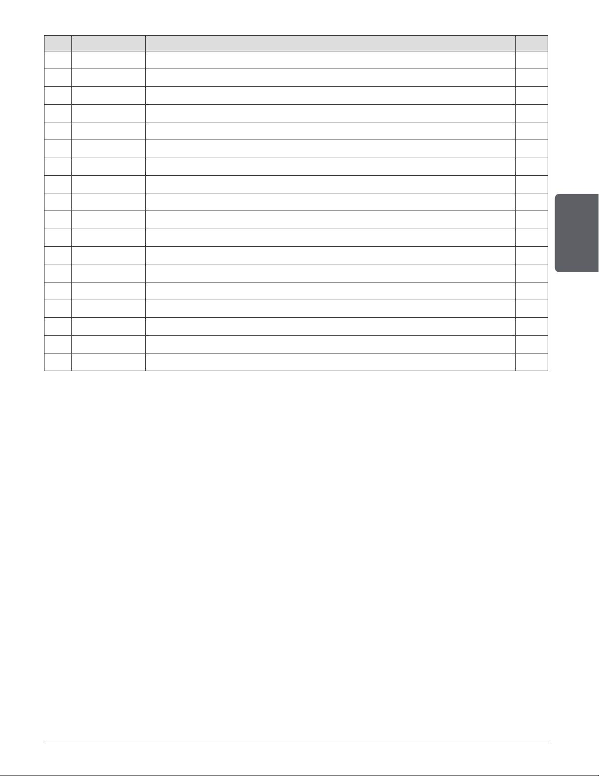
Page 61
Installation and operation manual - Bistro woodburning cookstove
ENGLISH
# Item Description Qty
35 21635 17" X 20 5/16" X 1/2" INSULATION 1
36 PL74534 INSULATING PROTECTIVE 1
37 30782 HEX FLANGE NUT SERRATED 1/4-20 STAINLESS 18-8 12
38 30128 1/4"-20 X 1 1/4" SOCKET SET SCREW 10
39 SE24361 TOP ASSEMBLY 1
40 PL24365 CAST IRON SPIGOT PAINTED 1
41 PL36899 DOUBLE WALL ADAPTOR 1
42 30024 1/4-20 X 1" MECHANICAL SCREW PAN QUADREX ZINC 2
43 AC06815 BLACK GASKET AND SILICONE KIT 3/16'' X 5' 1
44 24096 ROUND CAST IRON ASH PLUG 1
45 29007 3 1/4'' X 9'' X 1 1/4'' REFRACTORY BRICK 3
46 29010 4 1/2" X 9" X 1 1/4" REFRACTORY BRICK 4
47 29015 4'' X 9'' X 1 1/4'' REFRACTORY BRICK 14
48 SE65514 SECONDARY AIR TUBE KIT 1
49 PL65514 SECONDARY AIR TUBE 4
50 21388 20" X 12 1/2" X 1 1/4" VERMICULITE BAFFLE 1
51 SE46251 BISTRO INSTRUCTION MANUAL KIT 1
52 AC05959 METALLIC BLACK STOVE PAINT - 342 g (12oz) AEROSOL 1

BISTRO COOKING STOVE LIMITED LIFETIME WARRANTY
Cooking stove_Revision : June 2017
DROLET COOKING STOVE LIMITED LIFETIME WARRANTY
The warranty of the manufacturer extends only to the original retail purchaser and is not transferable. This warranty covers brand new
products only, which have not been altered, modified nor repaired since shipment from factory. Proof of purchase (dated bill of sale),
model name and serial number must be supplied when making any warranty claim to your DROLET dealer.
This warranty applies to normal residential use only. Damages caused by misuse, abuse, improper installation, lack of
maintenance, over firing, negligence or accident during transportation, power failures, downdrafts, venting problems or under-
estimated heating area are not covered by this warranty. The recommended heated area for a given appliance is defined by the
manufacturer as its capacity to maintain a minimum acceptable temperature in the designated area in case of a power failure.
This warranty does not cover any scratch, corrosion, distortion, or discoloration. Any defect or damage caused by the use of unauthorized
or other than original parts voids this warranty. An authorized qualified technician must perform the installation in accordance with the
instructions supplied with this product and all local and national building codes. Any service call related to an improper installation is not
covered by this warranty.
The manufacturer may require that defective products be returned or that digital pictures be provided to support the claim. Returned
products are to be shipped prepaid to the manufacturer for investigation. Transportation fees to ship the product back to the purchaser
will be paid by the manufacturer. All parts covered by this warranty are limited according to the table below.
The manufacturer, at its discretion, may decide to repair or replace any part or unit after inspection and investigation of the defect. The
manufacturer may, at its discretion, fully discharge all obligations with respect to this warranty by refunding the wholesale price of any
warranted but defective parts. The manufacturer shall, in no event, be responsible for any uncommon, indirect, consequential damages of
any nature, which are in excess of the original purchase price of the product. A one-time replacement limit applies to all parts benefiting
from lifetime coverage. This warranty applies to products purchased after March 1
st
, 2015.
DESCRIPTION
WARRANTY APPLICATION*
PARTS LABOUR
Combustion chamber (welds only) and cast iron door frame. Lifetime N/A
Surrounds, ash drawer, trims (extrusions), and convector air-mate. 5 years N/A
Removable stainless steel combustion chamber components, deflectors, and
supports.
5 years N/A
Glass retainers, handle assembly, and air control mechanism. 3 years N/A
Carbon steel combustion chamber components. 2 years N/A
Paint (peeling**), plating (defective manufacture**), ceramic glass (thermal
breakage only**), gaskets, insulation, and oven thermometer.
1 year
N/A
Firebricks, vermiculite combustion chamber components, oven mitt, and
cooking accessories.
N/A N/A
All parts replaced under the warranty.
90 days
N/A
*Subject to limitations above. **Picture required.
Shall your unit or a components be defective, contact immediately your DROLET dealer. To accelerate processing of your warranty
claim, make sure to have on hand the following information when calling:
Your name, address and telephone number;
Bill of sale and dealer’s name;
Installation configuration;
Serial number and model name as indicated on the
nameplate fixed to the back of your unit;
Nature of the defect and any relevant information.
Before shipping your unit or defective component to our plant, you must obtain an Authorization Number from your DROLET
dealer. Any merchandise shipped to our plant without authorization will be refused automatically and returned to sender.

NOTES :

Stove Builder International inc.
250, rue de Copenhague,
St-Augustin-de-Desmaures (Québec) Canada
G3A 2H3
418-908-8002
www.drolet.ca/en/
This document is available for free download on the
manufacturer’s website. It is a copyrighted document.
Resale is strictly prohibited. The manufacturer may update
this document from time to time and cannot be responsible
for problems, injuries, or damages arising out of the use
of information contained in any document obtained from
unauthorized sources.
