Loading ...
Loading ...
Loading ...
Installation
HP Installatio
n and User Instructions R00918
-10 09/15
Page
25
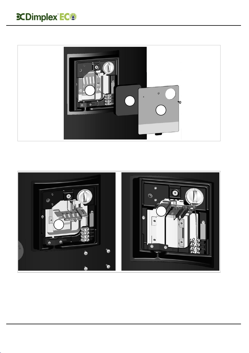
4.7.2 Connection of the sensor
Step 1: Access the sensor mounting plate. To do this remove the Dual Cut Out cover
plate (A) by removing the fixing screw and insulation foam (B) to access the sensor
mounting plate (C). Remove the M5 fixing screws in the four corners of the plate.
Step 2: Orientate the sensor mounting plate to allow access to the phials (four clips in
the centre of the sensor mounting plate). Be careful not to kink the capillaries that
connect the thermostat bulbs. The sensor mounting plate will have two vacant slots for
additional sensors (D). Slide the solar sensor into place as shown (E).
A
B
C
D
E
Loading ...
Loading ...
Loading ...