Loading ...
Loading ...
Loading ...
Installation
HP Installatio
n and User Instructions R00918
-10 09/15
Page
19
3.5 Limitations
- The heat pump must be specified
correctly, to ensure it is compatible
with the model of cylinder installed.
This is to prevent the heat pump
malfunctioning when preparing
domestic hot water.
- The heat exchangers in this range of
cylinders have been specifically
designed for heat pump applications.
Great care must be taken if using
these cylinders with other heat
sources, due to the heat exchange
capacity of the product.
4 Installation
4.1 Cold Water Inlet with
Inlet Control Group
4.1.1 Correctly site the
cylinder
Install the cylinder in an appropriate
location, ensuring all of the
recommendations have been
considered (see chapter 3.2).
4.1.2 Install the inlet group
The inlet group regulates the pressure
of the incoming mains water supply to
the cylinder and removes any debris
that might be water borne.
Note: Between the inlet group and
the cold water inlet on the cylinder
NO isolating device may be fitted,
as by doing so important safety
devices could be isolated!
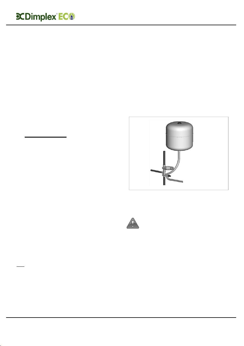
4.1.3 Expansion vessel
The expansion vessel is mandatory on
all EC-Eau cylinders and can be
connected directly to the cold water
inlet group, utilising the flexible hose
supplied with the vessel. The
expansion vessel should always be
fitted in accordance with the
manufacturer’s instructions. No
isolating device should be fitted
between the water cylinder and the
cold water inlet group.
Furthermore, it is recommended to
mount the vessel higher than the
cylinder to avoid having to drain the
cylinder when maintaining and
replacing the expansion vessel.
Figure 4: Connection of the expansion
vessel to the inlet group
It is important to check the
pre-charge pressure of the
expansion vessel membrane
before filling the cylinder. The
pre-charge should be greater
than or equal to 3bar.
Note: The expansion vessel must
be installed to the side of the
expansion relief valve on the inlet
group. To do this the blanking plug
must be removed and the
expansion vessel connected, as
shown in Figure 5.
Loading ...
Loading ...
Loading ...