Loading ...
Loading ...
Loading ...
-
ASSEMBLY INSTRUCTIONS
Read all assembly instructions completely before attempting assembly.
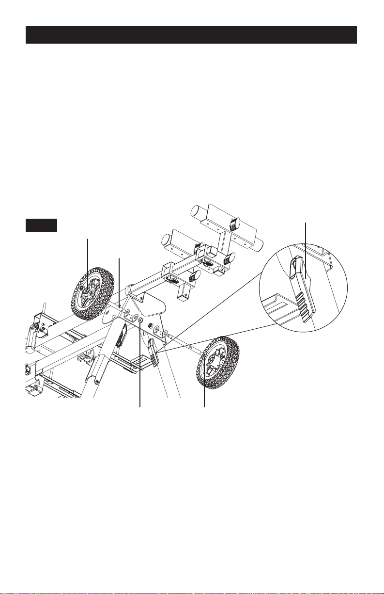
ATTACHING THE WHEELS
Figure 2
1. Extend the legs by depressing the leg lock levers.
2. Insert (8) axle through the mounting bracket and make sure the flat of the axle is inserted
into the flat of the inside of the mounting bracket.
3. Tighten (24) M10 nylon nut to the inner threaded portion of the axle.
4. Place (27) M12 washer then the (7) wheel onto the outer portion of the axle.
5. Place (26) M10 washer then (24) M10 nylon nut on the threaded portion of the outer portion
of the axle.
6. Repeat steps 2-5 for the other axle and wheel.
7. Ensure all (26) M10 nuts are tightened.
Leg Lock Lever
FIG 2
Washer M10
Axle
Nut M10 Washer M12
ATTACHING THE PULL HANDLE
Figure 3
1. Place one (18) spring washer and one (17) M8 washer onto (19) M8*20 bolt.
2. Place (19) M8*20 bolt through the back of the holes in the body as shown in Figure 3.
3. Place one (15) M8 nut into the square slot on the bottom of the handle.
4. Pass the bolt through the handle and use one hand to hold the handle and nut into position
and the other hand to tighten the bolt.
5. Repeat steps 1-4 for the other side of the handle.
6. Ensure bolts are tightened.
7. Once the handle is attached to the miter saw stand, feed the (29) GFCI through the middle
of the Miter Saw (9) Handle, it should fit snugly in the provided space.
Page 5
Loading ...
Loading ...
Loading ...