[A J
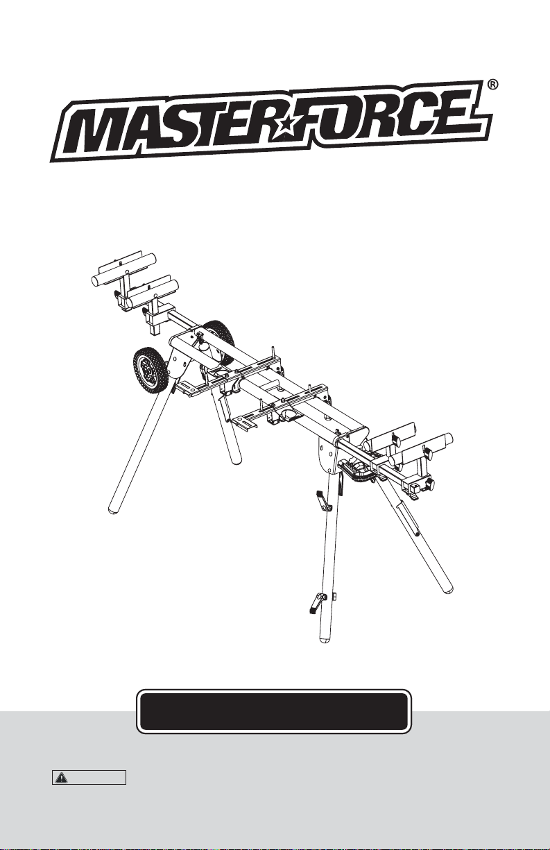
Miter Saw Workstation
240-1658
Customer Service: 1-800-255-7011
OPERATOR’S MANUAL
CAUTION:
To Reduce The Risk Of Injury, User Must Read And
Understand Operator’s Manual. Save These Instructions For Future Reference.

TABLE OF CONTENTS
Safety.......................................................................................................................Page 2
Features.................................................................................................................. Page 3
Overview................................................................................................................. Page 3
Parts List..................................................................................................................Page 4
Assembly Instructions............................................................................................. Page 5-13
Attaching the Wheels.............................................................................. Page 5
Attaching the Pull Handle........................................................................Page 5-6
Preparing the Stand................................................................................ Page 6
Assembling and Installing Material Work Supports.................................Page 7
Assembling Rapid Clamp Tool Mounts......................................................Page 8
Attaching the Bucket Handle...................................................................Page 9
Attaching Your Miter Saw or Other Benchtop Power Tool........................Page 9
Offset Mounting.......................................................................................Page 10
Attaching Cord Minder.............................................................................Page 10
Mounting the Miter Saw to the Stand...................................................... Page 11
To Remove Saw from Stand....................................................................Page 12
Transporting and Storing........................................................................ Page 12
Tool Mount Adjustment Screw.................................................................Page 12
To Adjust..................................................................................................Page 13
General Maintenance.............................................................................................. Page 13
Warranty.................................................................................................................. Page 14
Page 1

SAFETY
SAFETY WARNING
WARNING: Be sure to read and understand all safety instructions in this manual, including all
safety alert symbols such as “DANGER”, “WARNING” and “CAUTION” before using this power
tool accessory. Failure to follow all instructions listed in the manual may result in electric shock,
fire and/or serious personal injury.
GENERAL SAFETY INSTRUCTIONS FOR POWER TOOLS
Using power tools of any kind can be dangerous if safe operating procedures are not followed.
Recognizing the hazards of each tool and using them with respect and caution will considerably
limit the possibility of personal injury. However, if safety precautions are ignored, personal injury
will likely result. Always use common sense - your personal safety is your responsibility.
1. Know your power tool. Read and understand the Operator's Manual and observe the
warnings and instruction labels affixed to the tool.
2. Properly ground all tools.
3. Keep guards in place.
4. Remove adjusting keys and wrenches.
5. Keep work area clean and dry.
6. Keep children away.
7. Never leave running machines/tools unattended.
8. Disconnect tools from service.
9. Use correct tools for the job.
10. Never force a tool.
11. Wear safety apparel.
12. Wear safety glasses/goggles.
13. Never stand or sit on tools.
14. Replace damaged components immediately.
15. Make sure your work platform is sufficiently sturdy to do the specific job at hand.
16. Properly anchor blade for job being done.
17. Use correct blade for job being done.
18. Think Safety. Safety is a combination of operator awareness, common sense and alertness
at all times.
SAFETY INSTRUCTIONS FOR MITER SAW STATIONS
1. Use caution when folding or unfolding legs to limit any finger pinch points.
2. Place stand on flat and level surface to keep from rocking or tipping.
3. Make sure that work support extensions (if included) are within safe operating limits,
and are properly locked in place before using tool. Do not exceed the rated capacity on main
frame table.
4. Test the setup for stability before proceeding with work.
5. Be sure the miter saw is tightened securely at all mountings before folding the Miter Saw
Station for transport.
6. Use only the rapid clamp tool mounts included with this kit featuring the J-Lock
™
Clip.
Without this unique clip, it is possible that your tool could become dislodged from the mount
if bumped.
Page 2
1111
FEATURES
Your Miter Saw Workstation is loaded with standard features all designed and engineered to
maximize the functionality and flexibility of your Miter Saw Workstation.
STANDARD FEATURES
• Rapid Clamp Tool Mounts
• Adjustable Material Supports
• Wheels for easy transportation
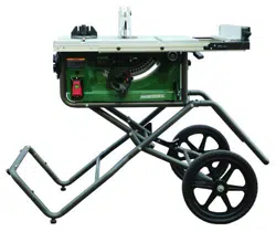
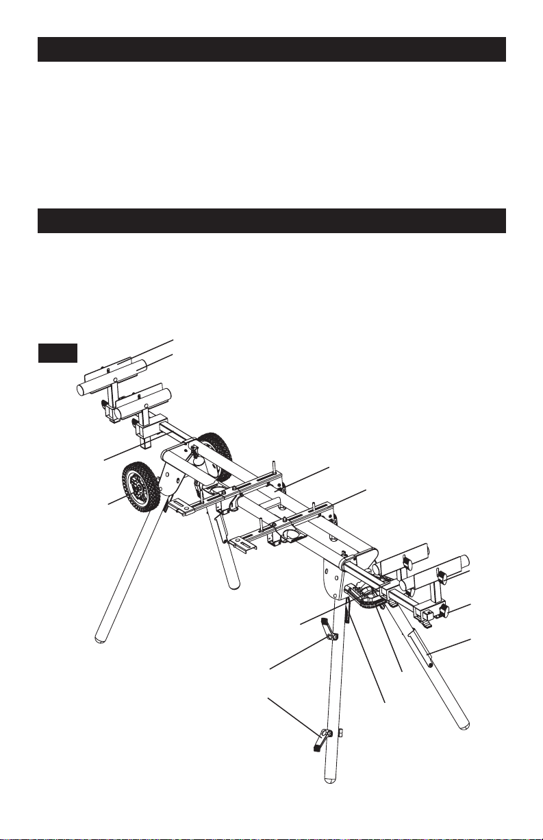
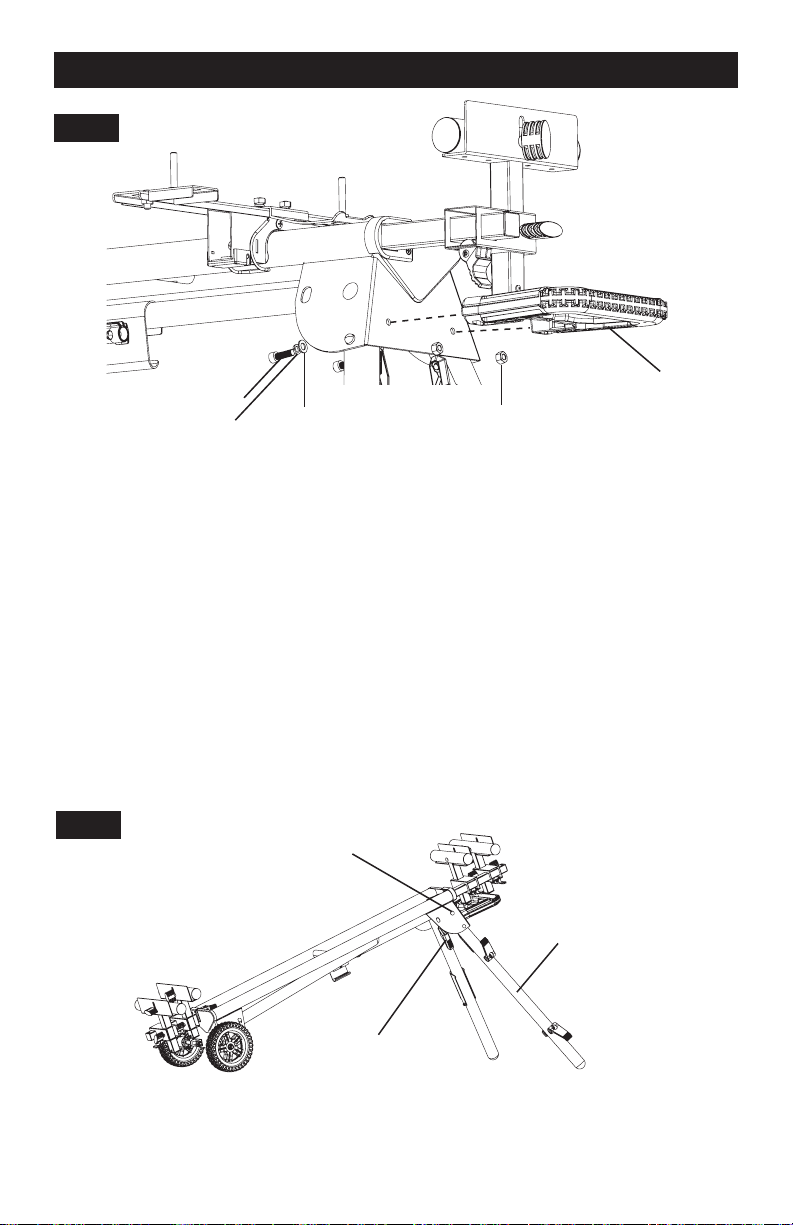
OVERVIEW
Figure 1
You have just purchased a Miter Saw Workstation. This product has been specifically designed
to assist you in the use of most miter saws, as well as increasing efficiency with other benchtop
tools such as table saws, band saws, scroll saws, planers, etc.
Work Stop
FIG 1
Material Support
Extension Rail
Miter Saw Stand
Rapid Clamp
Tool Mount
Wheel
Knob
Nut
Knob
Screw
Material Support Receiver
Material
Support
Cord Minder
Handle
Attachment
Quick-Release
Leg Lock Lever
Page 3
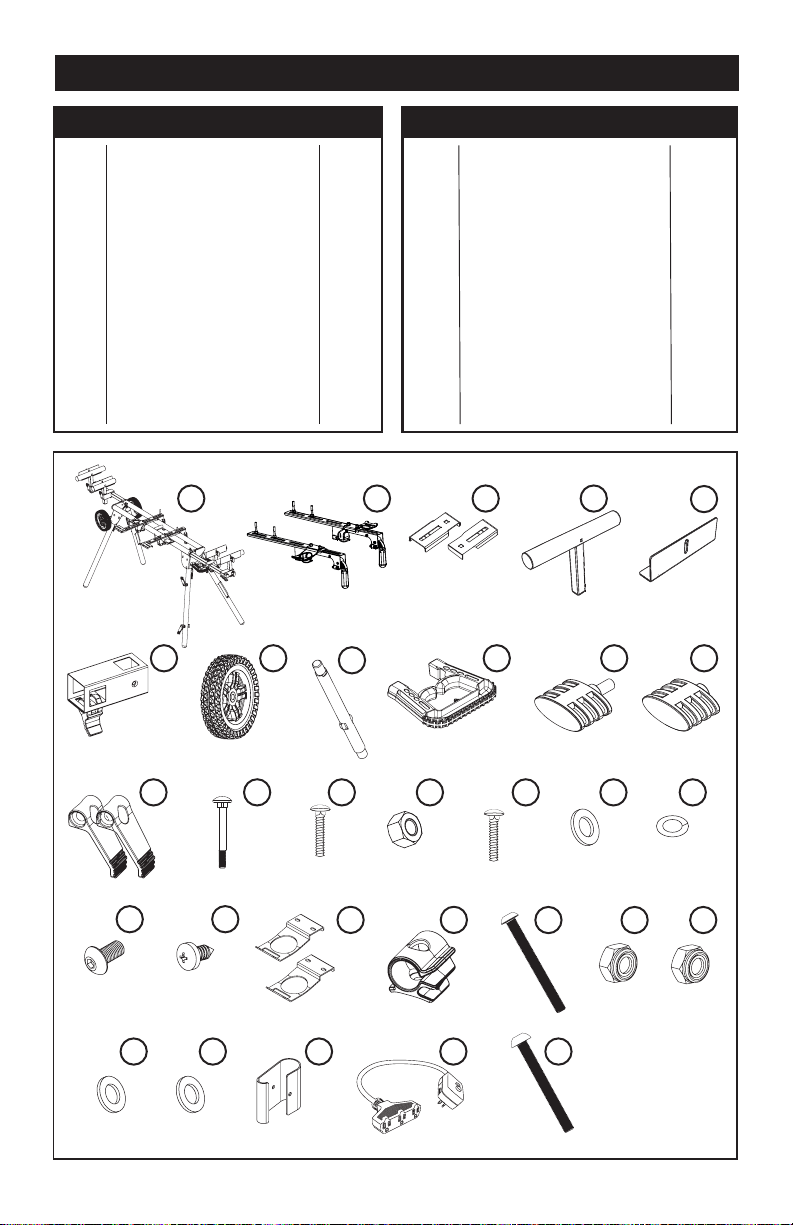
PARTS LIST
PART # DESCRIPTION QTY PART # DESCRIPTION QTY
1
MITER SAW WORKSTATION
1 pc
16
CARRIAGE BOLT M8*60
4 pcs
2
RAPID CLAMP TOOL MOUNT
2 pcs
17
WASHER M8
12 pcs
3
OFFSET MOUNTING BRACKET
2 pcs
18
SPRING WASHER M8
12 pcs
4
WIDE MATERIAL SUPPORT
4 pcs
19
BOLT M8*20
2 pcs
5
WORK STOP
4 pcs
20
SMALL SCREW
6 pcs
6
MATERIAL SUPPORT RECEIVER
4 pcs
21
STORAGE HANDLES
2 pcs
7
WHEEL
2 pcs
22
CORD CLIP
2 pcs
8
AXLE
2 pcs
23
M5*55 SCREW
2 pcs
9
HANDLE
1 pc
24
M10 NYLON NUT
4 pcs
10
KNOB SCREW
4 pcs
25
M5 NYLON NUT
3 pcs
11
KNOB NUT
4 pcs
26
WASHER M10
2 pcs
12
CORD MINDER ATTACHMENT
2 pcs
27
WASHER M12
2 pc
13
CARRIAGE BOLT M6*55
4 pcs
28
BUCKET HANGER
1 pc
14
CARRIAGE BOLT M8*20
6 pcs
29
GFCI
1 pc
15
NUT M8
12 pcs
30
M5*47 SCREW
1 pc
1 2 3 4
5
6 7
8
9
10 11
12 13 14 15 16
17
18
19 20
21 22
23 24 25
26 27
28 29 30
Page 4
-
ASSEMBLY INSTRUCTIONS
Read all assembly instructions completely before attempting assembly.
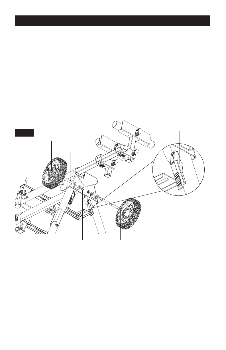
ATTACHING THE WHEELS
Figure 2
1. Extend the legs by depressing the leg lock levers.
2. Insert (8) axle through the mounting bracket and make sure the flat of the axle is inserted
into the flat of the inside of the mounting bracket.
3. Tighten (24) M10 nylon nut to the inner threaded portion of the axle.
4. Place (27) M12 washer then the (7) wheel onto the outer portion of the axle.
5. Place (26) M10 washer then (24) M10 nylon nut on the threaded portion of the outer portion
of the axle.
6. Repeat steps 2-5 for the other axle and wheel.
7. Ensure all (26) M10 nuts are tightened.
Leg Lock Lever
FIG 2
Washer M10
Axle
Nut M10 Washer M12
ATTACHING THE PULL HANDLE
Figure 3
1. Place one (18) spring washer and one (17) M8 washer onto (19) M8*20 bolt.
2. Place (19) M8*20 bolt through the back of the holes in the body as shown in Figure 3.
3. Place one (15) M8 nut into the square slot on the bottom of the handle.
4. Pass the bolt through the handle and use one hand to hold the handle and nut into position
and the other hand to tighten the bolt.
5. Repeat steps 1-4 for the other side of the handle.
6. Ensure bolts are tightened.
7. Once the handle is attached to the miter saw stand, feed the (29) GFCI through the middle
of the Miter Saw (9) Handle, it should fit snugly in the provided space.
Page 5
-
ASSEMBLY INSTRUCTIONS
FIG 3
Handle
M8*20 Bolt
Flat Washer
Nut M8
Spring Washer
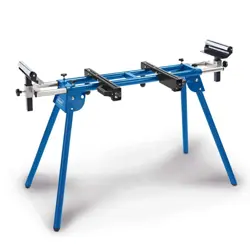
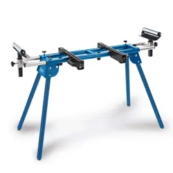
PREPARING THE STAND
Figure 4
1. Grab the (9) handle of the stand so that the wheels are on the ground and supporting the
weight of the stand.
2. Press the Quick Release Leg Lock Lever on one of the legs on the side of the handle and
rotate the leg downward until the locking pin clicks into place.
3. Repeat with the other leg on the side of the handle.
4. Lift the stand on the side with the wheels so that the weight is supported by the user and
the already opened legs.
5. Press the Quick Release Leg Lock Lever on one of the legs on the side of the handle and
rotate the leg downward until the locking pin clicks into place.
6. Repeat with the other leg on the side with the wheels.
7. Check to ensure the stand is stable and all of the legs have the locking pins engaged.
FIG 4
Locking Pin
Leg
Quick Release
Leg Lock Lever
Page 6
-
ASSEMBLY INSTRUCTIONS
ASSEMBLING AND INSTALLING MATERIAL WORK SUPPORTS
Figure 5
1. Slide one (13) M6*55 carriage bolt through the square hole in the (4) wide material support
and extend through the other side.
2. Place the (5) work stop over the end of the bolt.
3. Thread one (11) knob nut over the end of the bolt and tighten to secure.
4. Slide the wide material support rail through the hole in the top of the (6) material
support receiver.
5. Insert one (10) knob screw through the small hole on the side of the material support
receiver and tighten to secure.
6. Insert one (20) small screw into the bottom of the wide material support rail and tighten
to secure.
7. Slide the (6) material support receiver over the extension rail so that the extension rail
extends through the opening in the receiver. Position the work support at the desired
location on the extension rail.
8. Insert one (20) small screw into the back of the extension rail and tighten to secure.
9. Repeat with other supports.
FIG 5
Work Stop
Knob Nut
Material
Wide
Material
Support
Support
Receiver
Knob Screw
Knob Nut
Knob Nut
Knob Screw
Small Screw
Handle
Extension Rail
Small Screw
Page 7
-
ASSEMBLY INSTRUCTIONS
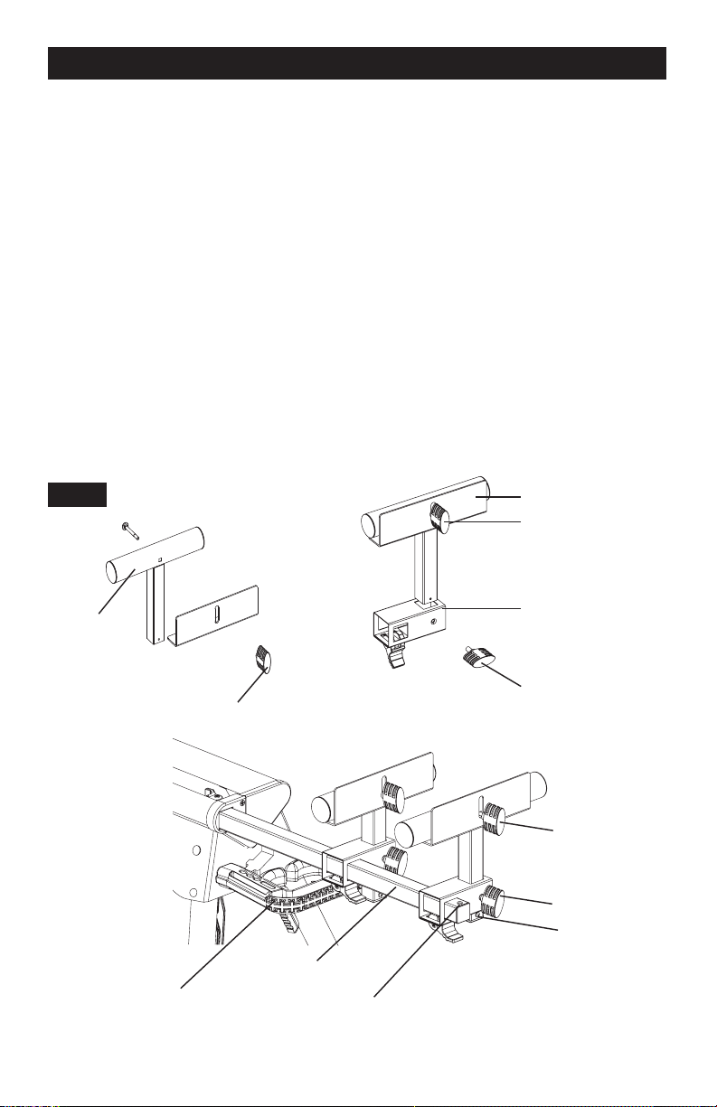
ASSEMBLING RAPID CLAMP TOOL MOUNTS
Figure 6
1. Lay out all parts before starting the assembly process.
2. Select one (21) storage handle and position it where desired on one (2) Rapid Clamp Tool
Mounting Rail. Run two (14) M8*20 carriage bolts through the slots in the rail arms and
attach using a (17) M8 washer and nut. These handles are designed to store tools and can
be located where most convenient for the user by sliding it along the rail. See Figure 6.
Tighten the bolts and repeat for the second arm. The handles should face opposite
directions (outward) when the two completed arms are next to each other.
3. Attach the rapid clamp tool mounting rail to the lower portions of the (2) rapid clamp tool
mounting base using one (in each) (14) M8*20 carriage bolts and one (in each) (15) M8
nuts, making sure that the threaded portion is facing down toward the base (only hand
tighten at this point).
4. To determine the best placement of the power tool on the rapid clamp tool mounting rail,
place the rapid clamp tool mounts onto the body of the Miter Saw Workstation and estimate
the tool’s center of gravity as it relates to the Miter Saw Workstation. The rapid clamp tool
mounting rail can be adjusted forward and/or backward as needed, as long as its excess
material doesn’t affect workflow during the normal use of the tool.
5. Tighten down the (15) M8 nuts that were placed in the rapid clamp tool mounting rail and
rapid clamp tool mount base in Step 3.
6. The rapid clamp tool handle and tool storage arms can be placed anywhere along the rapid
clamp tool mounting rail. Hold the rapid clamp tool handle and tool storage arms in place
using two (14) M8*20 carriage bolts and two (15) M8 nuts.
NOTE: If the tool has holes that do not line up with the slots in the tool mounts, then
use the Offset Mounting Brackets (see Figure 9).
FIG 6
Rapid Clamp Tool
Mount Base
Rapid Clamp Tool
Mounting Rail
Storage
Handle
Page 8

-
~
-
ASSEMBLY INSTRUCTIONS
ATTACHING THE BUCKET HANGER
Figure 7
1. Place (28) bucket hanger hoop over the central tubing.
2. Feed (30) M5*47 bolt through cord snap then through the bucket hanger.
3. Apply (25) M5 Nylon nut and tighten.
FIG 7
M5*47 Screw
M5 Nylon Nut
Bucket Hanger
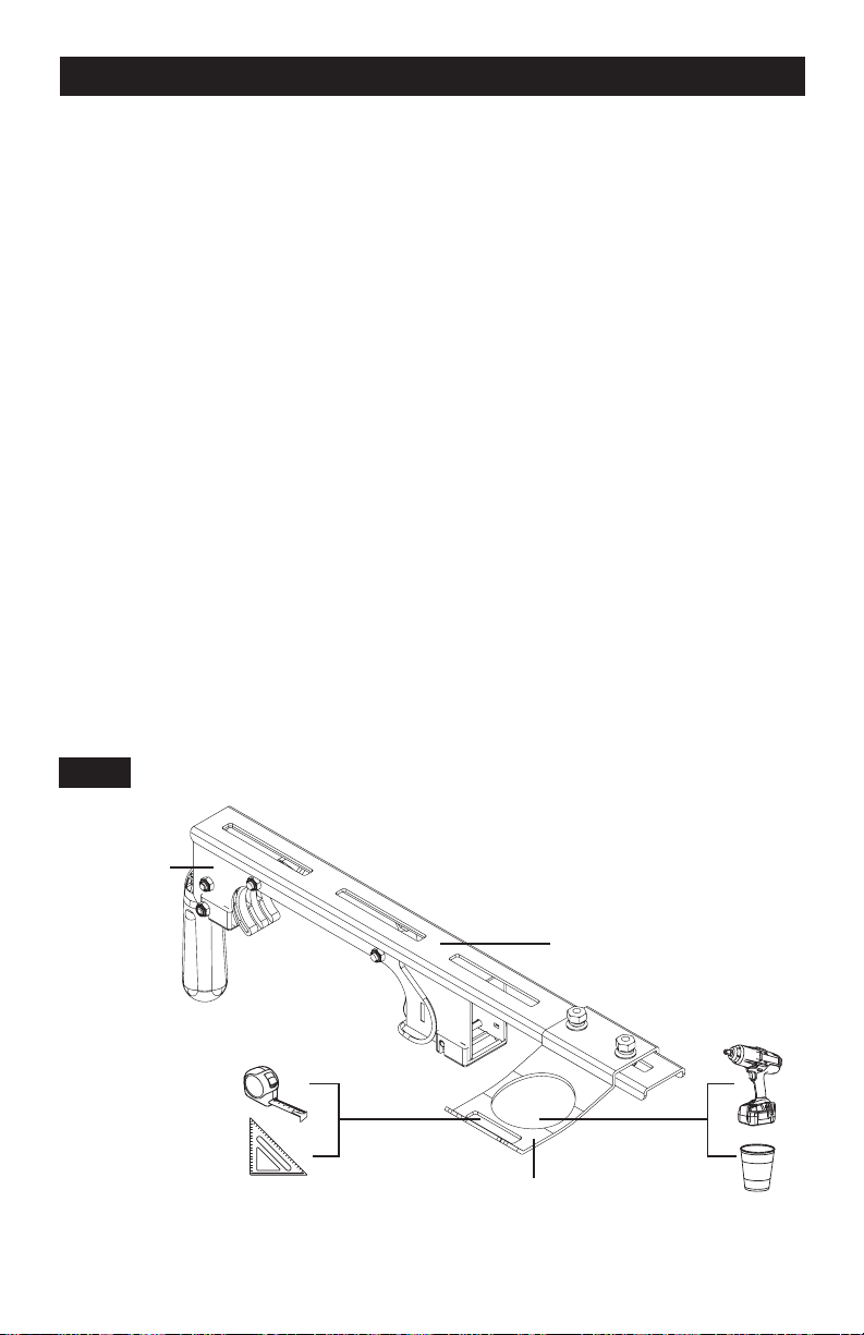
ATTACHING YOUR MITER SAW OR OTHER BENCHTOP POWER TOOL
Figure 8
Various bench top tools can be used with your Miter Saw Workstation by attaching them to the
Rapid Clamp Tool Mounts. Always position the saw to achieve maximum balance and stability.
All four corners of the saw must be bolted to the tool mounts before use. Make sure bolts do not
extend above the table of the miter saw.
1. Unplug the saw and lock the saw arm in the down position.
2. Place a tool mount underneath the saw, aligning the mounting holes on the miter saw base
with the slot in the top of the tool mount.
3. Feed one (16) M8*60 carriage bolt up through both the tool mount and a mounting hole in
the saw.
4. Secure in place using a (17) flat washer, (18) spring washer, and (15) M8 nut.
5. Repeat through the other end of the tool mount.
6. Place the second tool mount underneath the other side of the saw, aligning the mounting
holes on the miter saw base with the opening in the tool mount.
7. Install (16) M8*60 carriage bolts as previously described.
8. After making sure both tool mounts are parallel to each other, finger tighten all four nuts to
hold in position.
NOTE: If the saw has holes that do not line up with the slots in the tool mounts, use the
offset mounting brackets.
FIG 8
Page 9
-
- ~ ~ ( _
II . ( \
t
I)
ASSEMBLY INSTRUCTIONS
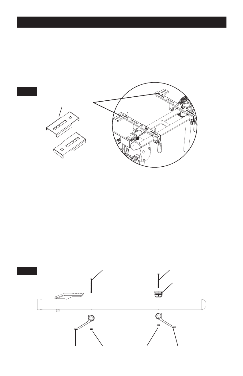
OFFSET MOUNTING
Figure 9
Offset mounting bracket for miter saws and/or power tools with an irregular mounting hole pattern.
Instructions: Secure (3) offset mounting brackets as shown using the supplied (16) M8*60
carriage bolts. These brackets can be used on the front or rear of the rapid clamp tool mounts to
accommodate your specific power tool.
FIG 9
Offset Mounting Brackets
ATTACHING CORD MINDER
Figure 10
1. Locate leg with 2 pass-through holes. (handle side)
2. Pass one (23) M5*55 screw through the top hole of the leg and through the (12) plastic cord
minder attachment, making sure that the tip of the cord minder attachment is pointing up
towards the top of the stand.
3. Apply (25) M5 nylon nut and tighten.
4. Pass one (23) M5*55 screw through the (22) cord clip then through the body and the plastic
cord minder attachment, making sure that the tip of the cord minder attachment is pointing
down towards the ground.
5. Apply (25) M5 nylon nut and tighten.
M5*55 Screw M5*55 Screw
FIG 10
Cord Clip
Cord Minder M5 Nylon Nut M5 Nylon Nut Cord Minder
Attachment Attachment
Page 10
-
ASSEMBLY INSTRUCTIONS
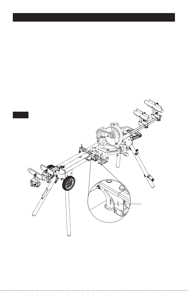
MOUNTING THE MITER SAW TO THE STAND
Figure 11
Use the handles located at the rear of the tool mounts to aid in installing or removing saw and
tool mount assembly.
1. Lift the saw and tool mount assembly, allowing the assembly to tilt slightly toward
your body.
2. While still tilted toward you, hook the front edge of the tool mount assembly onto the front
rail of the stand.
3. Lower the tool mount assembly to allow the rear edge of the tool mount to seat fully over the
rear rail.
4. Lock the tool mounts in position by lowering the locking levers.
5. Snap the J-Lock
™
clip closed (around the beams) to prevent your mounted tool from
detaching from the MASTERFORCE® Miter Saw Workstation.
FIG 11
A
J-Lock
™
Clip
NOTE: Continue to hold the tool mount assembly with one hand until both levers are
securely locked.
6. Check position and adjust if necessary to make sure the weight of the saw is evenly
balanced over the rails.
7. Ensure the saw is seated and locked in position, then securely tighten the four nuts holding
the saw to the tool mounts.
Page 11
-
-
ASSEMBLY INSTRUCTIONS
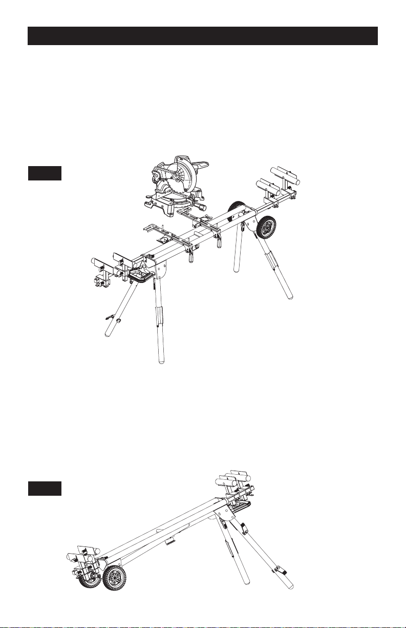
TO REMOVE SAW FROM STAND
Figure 12
1. Raise the locking levers to unlock the saw and tool mounts.
2. Unsnap the J-Lock
™
clips from around the mounting beams to allow your tool to separate
from your MASTERFORCE
®
Miter Saw Workstation.
3. Lift away from the rear rail of the stand to disengage.
4. With the assembly tilted slightly toward you, lift the assembly to disengage from the front
rail of the Miter Saw Workstation.
FIG 12
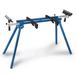
TRANSPORTING AND STORING
Figure 13
1. Before storing or transporting, make sure all attachments are secure and bench top
tool is removed.
2. Collapse legs and make sure they are locked into the up position.
3. Use the (9) handle that is located on the end of the product for transporting.
4. Pull up on the handle and tilt Miter Saw Workstation until weight is distributed evenly
onto wheels.
FIG 13
Page 12
-
ASSEMBLY INSTRUCTIONS
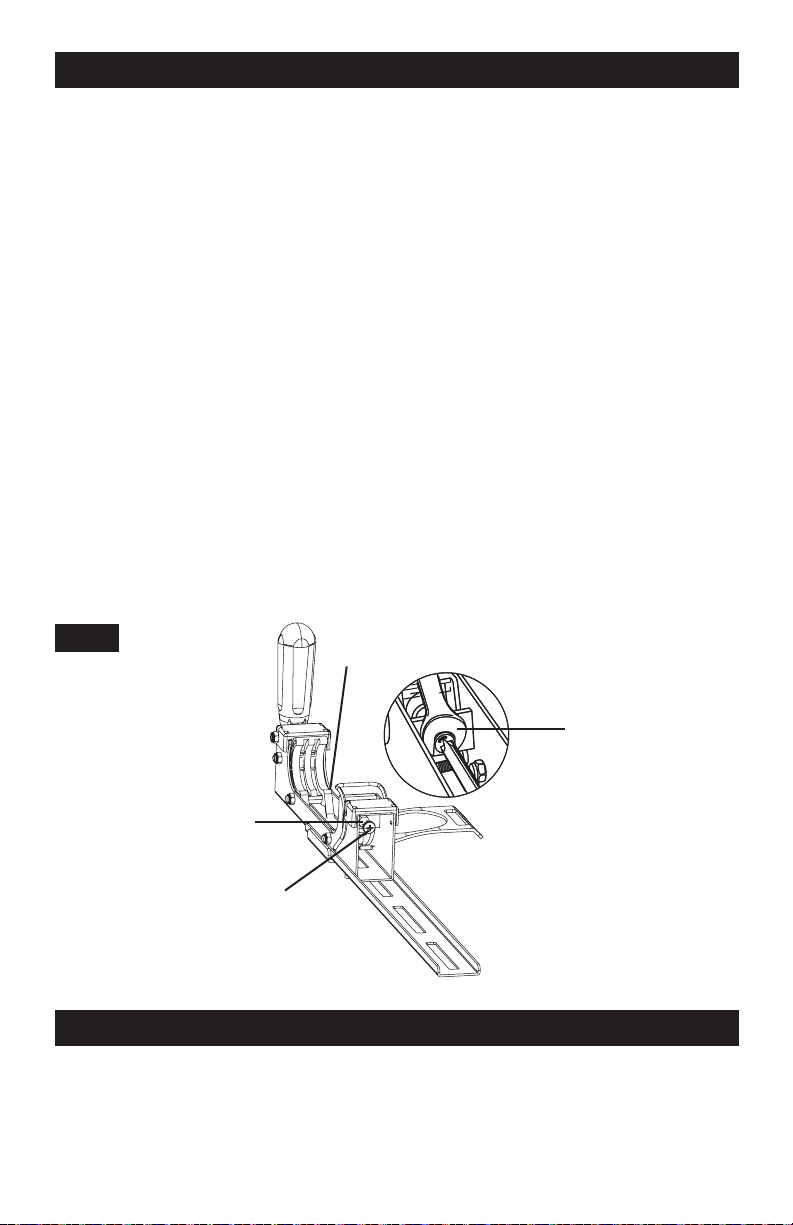
TOOL MOUNT ADJUSTMENT SCREW
Most plastic tool mounts are designed to fit snugly over the stand rails. With the locking levers in
the lowered (locked) position, you should not be able to remove the saw and tool mount
assembly from the rails. If the saw and tool mount can be removed from the rails when the levers
are locked, the tool mount adjustment screws need to be tightened. If the saw and the tool
mount assembly will not fit over both rails, the bracket adjustment screws needs to
be loosened.
NOTE: The saw should be removed from the tool mounts before attempting to tighten or
loosen the tool mount adjustment screws.
TO ADJUST
Figure 14
1. Use a wrench to slightly loosen the nut.
2. Turn the screw with a Phillips screwdriver. Rotate clockwise if the tool mount assembly
needs to be tightened or counter-clockwise if the assembly needs to be loosened.
3. Install the tool mount on the Miter Saw Workstation rails and lower the locking lever to check
the adjustment.
4. When the correct position is achieved, tighten the nut with a 10mm open-ended wrench
to secure.
5. Repeat steps 1-4 to attach the second tool mount.
FIG 14
Wrench
M6 Nut
Tool Mount
Tool Mount
Adjustment Screw
GENERAL MAINTENANCE
Avoid using solvents when cleaning plastic parts. Most plastics are susceptible to damage
from various types of commercial solvents and may be damaged by their use. Use clean cloths
to remove dirt, dust, oil, grease, etc.
Page 13

Miter Saw Workstation
WARRANTY
90-DAY MONEY BACK GUARANTEE
This MASTERFORCE
®
brand tool carries our 90-Day Money Back Guarantee.
If you are not completely satisfied with your MASTERFORCE
®
brand tool for
any reason within ninety (90) days from the date of purchase, return the tool with your
original receipt to any MENARDS
®
retail store, and we will provide you a refund - no
questions asked.
3-YEAR LIMITED WARRANTY
This MASTERFORCE
®
brand tool carries our famous No Hassle 3-Year Limited
Warranty to the original purchaser. If, during normal use, this MASTERFORCE
®
tool
breaks or fails due to a defect in material or workmanship within three (3) years from the
date of original purchase, simply bring the tool with the original sales receipt back
to your nearest MENARDS
®
retail store. At its discretion, MASTERFORCE
®
agrees
to have the tool or any defective part(s) repaired or replaced with the same or similar
MASTERFORCE
®
product or part free of charge, within the stated warranty period,
when returned by the original purchaser with original sales receipt. Not withstanding the
foregoing, this limited warranty does not cover any damage that has resulted from abuse
or misuse of the Merchandise. This warranty: (1) excludes expendable parts including
but not limited to blades, brushes, belts, bits, light bulbs, and/or batteries; (2) shall be
void if this tool is used for commercial and/or rental purposes; and (3) does not cover
any losses, injuries to persons/property or costs. This warranty does give you specific
legal rights and you may have other rights, which vary from state to state. Be careful,
tools are dangerous if improperly used or maintained. Seller’s employees are not
qualified to advise you on the use of this merchandise. Any oral representation(s) made
will not be binding on seller or its employees. The rights under this limited warranty are
to the original purchaser of the merchandise and may not be transferred to any
subsequent owner. This limited warranty is in lieu of all warranties, expressed or implied
including warranties or merchantability and fitness for a particular purpose. Seller shall
not be liable for any special, incidental, or consequential damages. The sole exclusive
remedy against the seller will be for the replacement of any defects as provided herein,
as long as the seller is willing or able to replace this product or is willing to refund the
purchase price as provided above. For insurance purposes seller is not allowed to
demonstrate any of these power tools for you.
For questions / comments, technical assistance or repair parts -
Please call toll free at: 1-800-255-7011 (M-F 8am - 6pm CST).
SAVE YOUR RECEIPTS
THIS WARRANTY IS VOID WITHOUT THEM
Page 14

/MISBM;iJRCEJ;
© 2020 Menard, Inc., Eau Claire, WI 54703