Quick Installation Guide
RTH2510/RTH2410 Series
Programmable Thermostat
69-2726EF-01

69-2726EF— 01 ii
Identify System Type
This thermostat is compatible with the following systems:
Gas, oil or electric furnace
Central air conditioner
Hot water system with or without pump
Millivolt system
Central heating and cooling system
Heat pump without auxiliary/backup heat
Heat pump with auxiliary/backup heat
Do you need assistance?
We are here to help.
Call 1-800-468-1502 for wiring
assistance before returning
the thermostat to the store.
This thermostat cannot be used on multistage systems.
1 69-2726EF—01
1
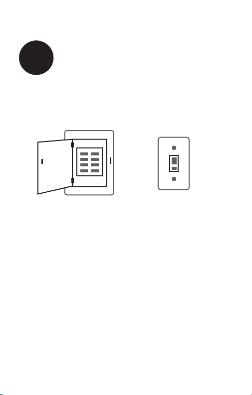
Turn Off Power to Heating/
Cooling System
or
OFF
69-2726EF— 01 2
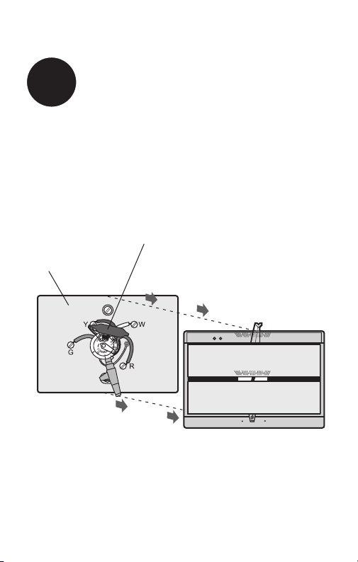
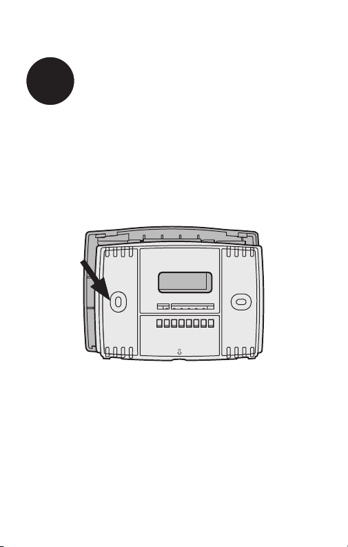
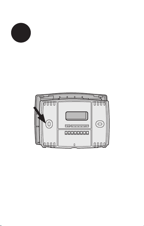
Remove old thermostat but leave wallplate with
wires attached.
Remove Old Thermostat
2
50 60 70 80 F
OFF
AUTO EM. HEAT
EM. HEATAUX. HEAT
50 60 70 80
M33835
Is there a sealed tube containing
mercury? If so, see back cover for
proper disposal instructions.
Old thermostat
Cover
Do not remove
wallplate yet
3 69-2726EF—01
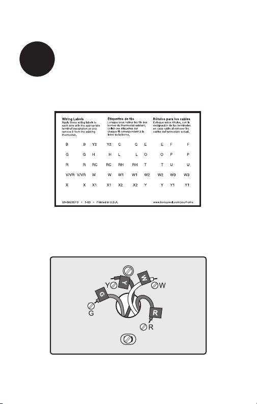
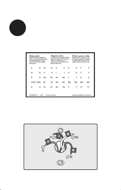
Label Wires with Tags
3
Label the wires using the supplied wire labels as you
disconnect them.
Wire Labels
M28100
M33763
69-2726EF— 01 4
M32731
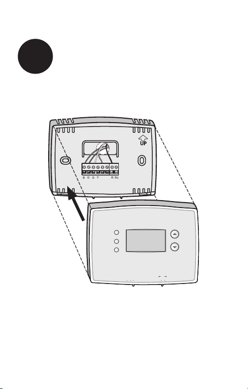
TO REMOVE WALLPLATE
PULL HERE
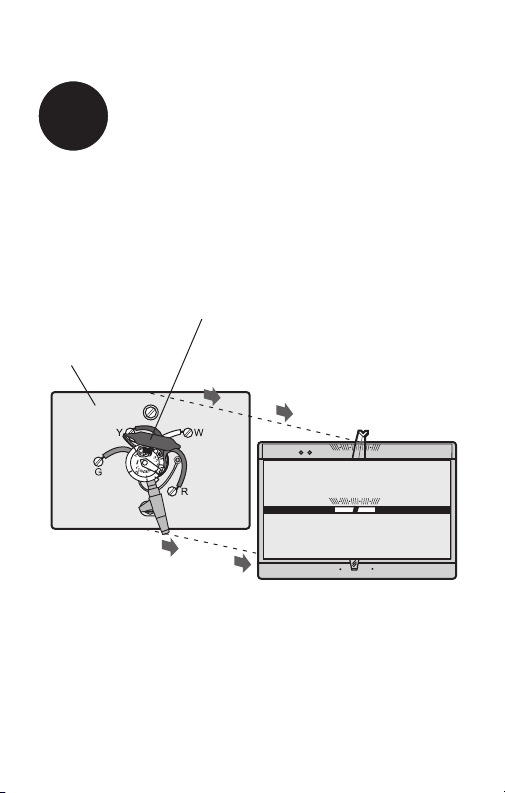
Separate Wallplate from
New Thermostat
4
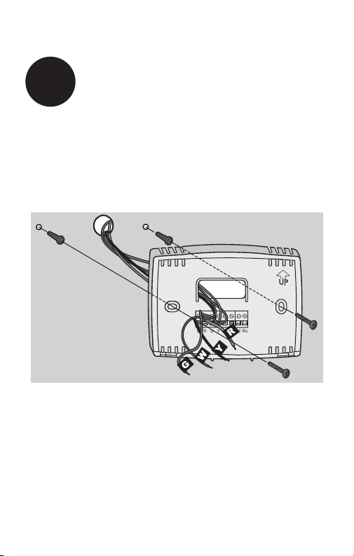
Remove wallplate from the new thermostat and mount onto
wall.
Wallplate
5 69-2726EF—01
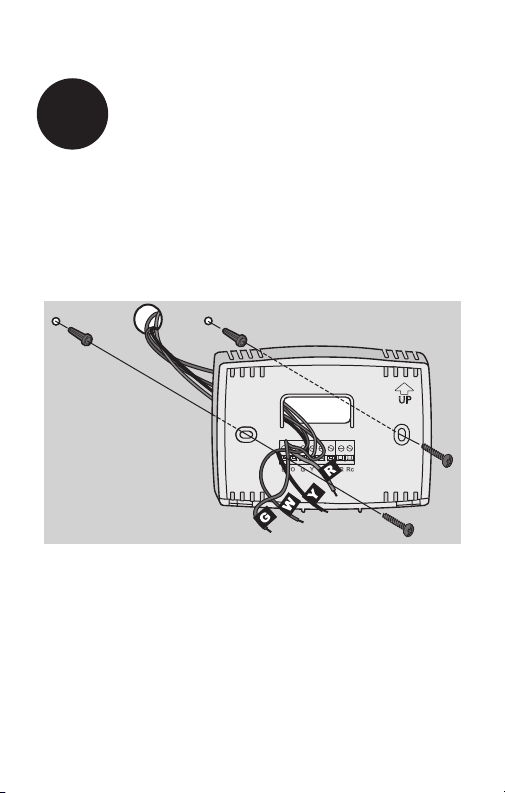
Mount the new wallplate using the included screws
and anchors.
5
Mount Wallplate
Drill 3/16-in. holes for drywall
Drill 3/32-in. holes for plaster
W/
Aux
Not
Used
M32714
69-2726EF— 01 6
M32715
SCREW
INSERT WIRES
AND TIGHTEN
SCREWS
WIRE
HOLE
LABELED
WIRES
W/
Aux
W
Y
G
R
Not
Used
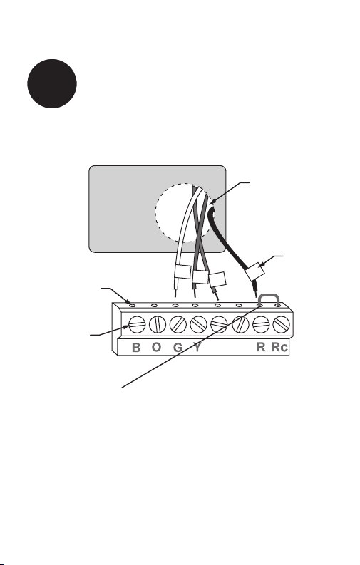
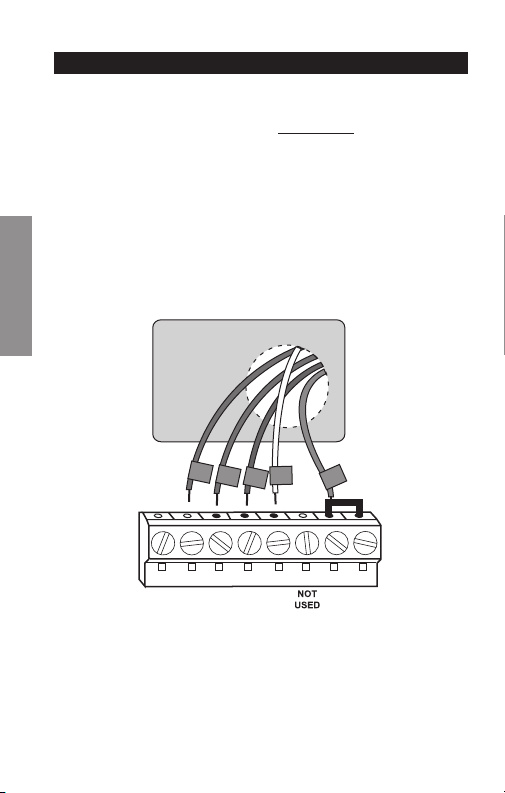
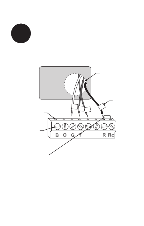
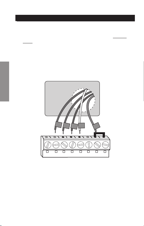
Connect Wires
6
Simply match wire labels.
Remove metal jumper if you have both R and Rc wires.
Labels don’t match? See page 23.
Have a Heat Pump system? See page 24.
We are here to help.
Call 1-800-468-1502 for wiring assistance.

7 69-2726EF—01
RTHXXXX
M32707
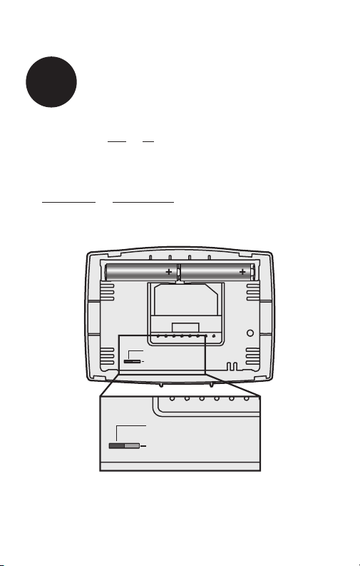
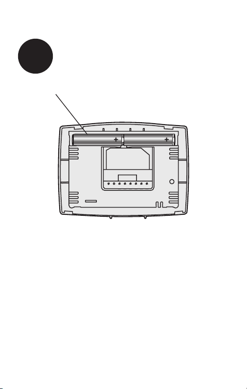
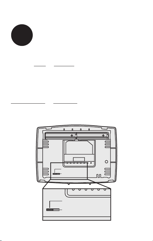
Install two AAA alkaline batteries.
Back of thermostat
7
Install Batteries
69-2726EF— 01 8
Move the switch to the proper setting:
Gas or Oil: For gas or oil heating systems, leave the fan
operation switch in this factory-set position (for systems that
control the fan in a call for heat).
Electric or Heat Pump: Change the switch to this setting
for heat pump or electric heat systems. (This setting is for
systems that allow the thermostat to control the fan in a call
for heat, if a fan wire is connected to the G terminal.)
8
Set fan operation switch
RTHXXXX
M32716
GAS OR OIL
ELECTRIC OR HEAT PUMP
GAS OR OIL
ELECTRIC OR HEAT PUMP
9 69-2726EF—01
W/
Aux
Not
Used
M33592
Heat Off Cool Auto On
Fan
Heat Off Cool
Auto On
Fan
Heat Off Cool Auto On
Fan
Heat Off Cool
Auto On
Fan
Set
Hold
Run
Install thermostat onto the wallplate on the wall.
9
Install Thermostat onto Wallplate

69 -2726EF— 01 10
Turn the power back on to the heating/cooling system.
10
Turn Power Back On
or
ON

11 69-2726EF—01
If your system type is:
q Single Stage Heat and Cool
q Heat Only or Cool Only
Congratulations, you’re done!
If your system type is:
q Heat Pump* with Backup Heat
Continue with advanced installation
on next page to match your thermostat to your system
type.
*Heat Pump—an air conditioner that provides cooling in the
summer, and also runs in reverse in the winter to provide
heating.
If you are not sure of your system type or if you have
other questions, call us toll-free at 1-800-468-1502.
This thermostat works on 24 volt or 750 mV systems. It will
NOT work on multi-stage conventional systems or 120/240
Volt systems.
11
If your system type is...

Advanced Installation
Enter system setup .............................................................. 13
Changing settings ................................................................ 14
System type ......................................................................... 15
Heating cycle rate ................................................................16
Early start ............................................................................17
Temperature display ............................................................18
Compressor protection ........................................................19
Clock display .......................................................................20
Change filter timer ...............................................................21
Restore program schedule default ......................................22
Wiring conventional system .................................................23
Wiring heat pump ................................................................24
Troubleshooting ...................................................................26
Customer assistance ...........................................................27
RTH2510/RTH2410
13 69-2726EF—01
SETUP WIRING ASSISTANCE TROUBLESHOOTING
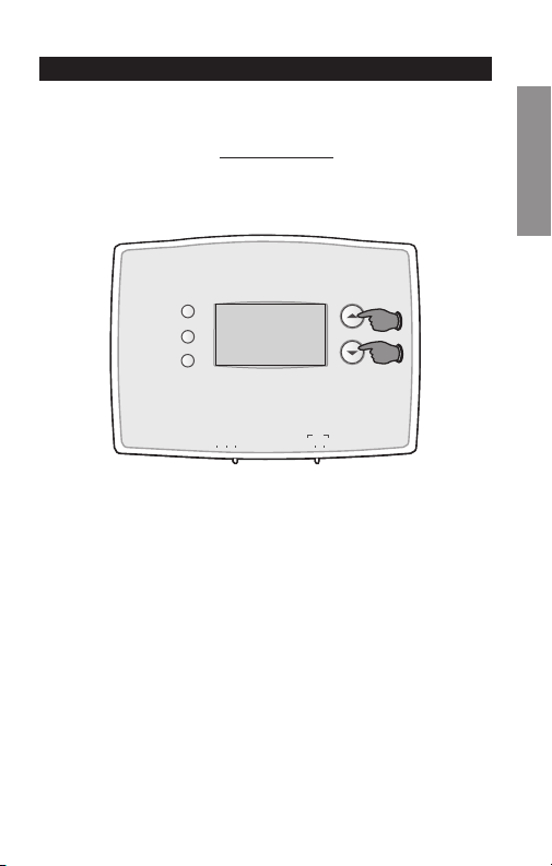
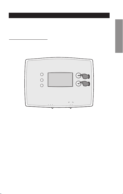
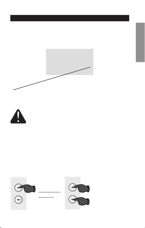
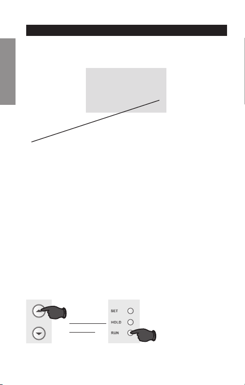
Enter System Setup
System setup
To enter system setup, press and hold both the s and
t buttons until the display changes (approximately 5
seconds).
M33593
Heat Off Cool Auto On
Fan
Heat Off Cool
Auto On
Fan
Set
Hold
Run
Advanced Installation Guide
69 - 2726 EF— 01 14
SETUPWIRINGASSISTANCETROUBLESHOOTING
1
0
M33594
Set
Hold
Run
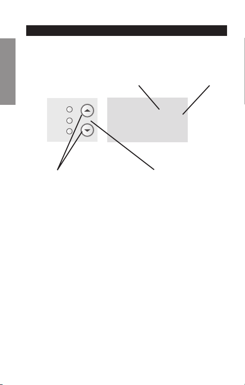
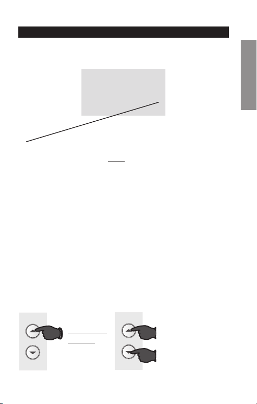
System setup
Change Function Change Setting
See pages 15–21 to change Function Settings.
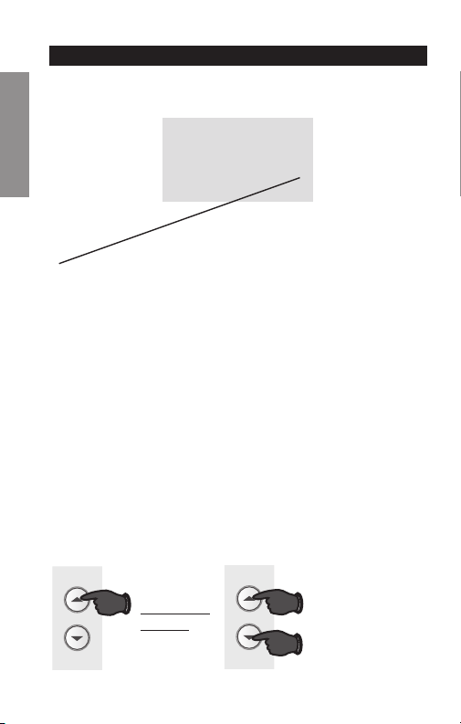
Changing Settings
Function Setting
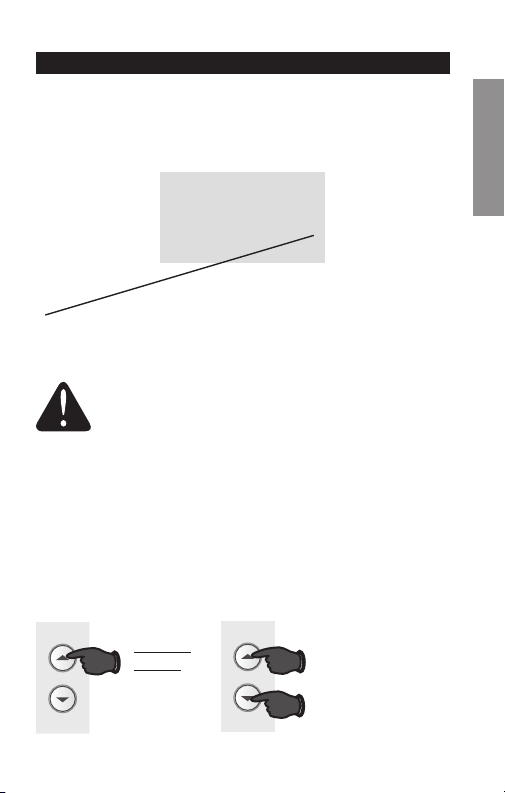
1. Press the s or t button to change the setting.
2. Press the s and t buttons simultaneously for one
second to advance to the next function.
3. Press the Run button to exit and save settings.
NOTE: If you do not press any button for 60 seconds while
you are in the setup menu, the thermostat automatically
saves any changes made and exits the menu.

RTH2510/RTH2410
15 69-2726EF—01
SETUP WIRING ASSISTANCE TROUBLESHOOTING
1
0
M32718
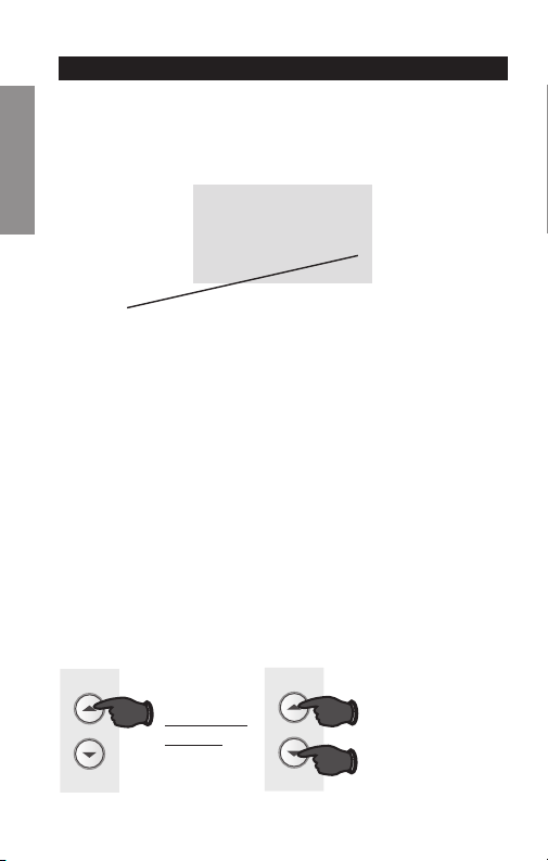
System setup
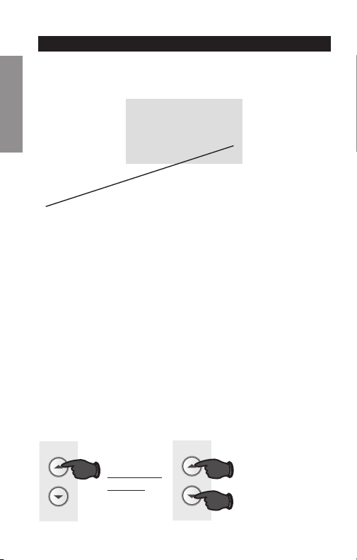
Function 1: System Type
0 Heating & cooling: Gas, oil or electric heating with
central air conditioning or heat pump without auxiliary/
back-up heat.
1 Heat pump with auxiliary/backup heat: Outside
compressor provides both heating and cooling.
Press the s or t button to select the type of Heat/Cool
system you have in your home.
Press to
change
setting.
When finished,
press s and t
to advance to the
next function.
M33591
AND
OR

Advanced Installation Guide
69 -2726EF— 01 16
SETUPWIRINGASSISTANCETROUBLESHOOTING
5
5
M32720
System setup
Press the s or t button to select your heating system
and optimize its operation.
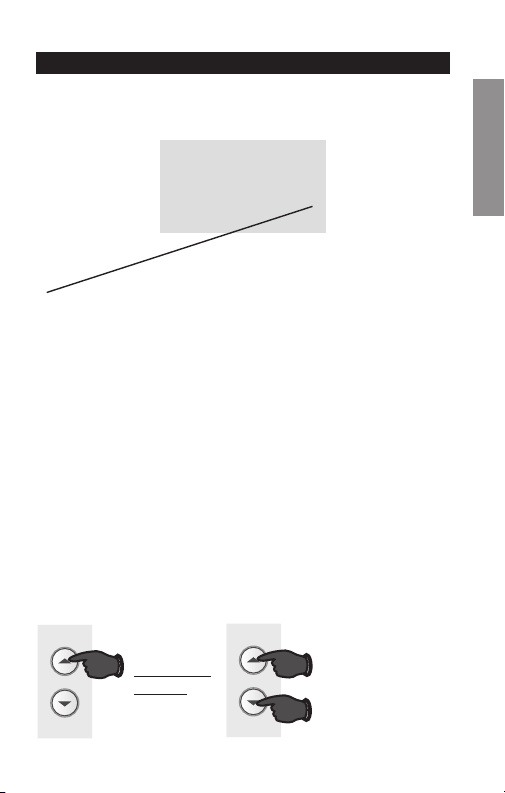
Function 5: Heating cycle rate
5 Gas or oil furnace: Use this setting if you have a
standard gas or oil furnace that is less than 90%
efficient.
6 Electric furnace: Use this setting if you have any type
of electric heating system.
3 Hot water or high-efficiency furnace: Use this
setting if you have a hot water system or a gas furnace
of greater than 90% efficiency.
2 Gas/oil steam or gravity system: Use this setting if
you have a steam or gravity heat system.
Press to
change
setting.
When finished,
press s and t
to advance to the
next function.
M33591
AND
OR
RTH2510/RTH2410
17 69-2726EF—01
SETUP WIRING ASSISTANCE TROUBLESHOOTING
13
1
M32721
System setup
Press the s or t button to select Early Start.
Function 13: Early Start
1 On
0 Off
Early start allows the heating or cooling to turn
on before the program start time, so the tem-
perature is reached at the time you set. Simply
program the desired times and temperature
into the schedule. The thermostat will turn the
heating or cooling on early so that the desired
temperature is reached at the desired time.
Press to
change
setting.
When finished,
press s and t
to advance to the
next function.
M33591
AND
OR
Advanced Installation Guide
69 -2726EF — 01 18
SETUPWIRINGASSISTANCETROUBLESHOOTING
System setup
Function 14: Temperature display
0 Fahrenheit temperature display (°F)
1 Celsius temperature display (°C)
Press the s or t button to select Fahrenheit or Celsius
temperature display.
14
0
M32722
Press to
change
setting.
When finished,
press s and t
to advance to the
next function.
M33591
AND
OR

RTH2510/RTH2410
19 69-2726EF—01
SETUP WIRING ASSISTANCE TROUBLESHOOTING
System setup
Function 15: Compressor Protection
1 On
0 Off
Press the s or t button to select Compressor Protection
settings.
Compressor Protection: This feature forces the com-
pressor to wait approximately 5 minutes before restarting,
to prevent equipment damage. During the wait time, the
message “Cool On” or “Heat On” is displayed on screen.
15
1
M32723
Press to
change
setting.
When finished,
press s and t
to advance to the
next function.
M33591
AND
OR
Advanced Installation Guide
69-2726EF— 01 20
SETUPWIRINGASSISTANCETROUBLESHOOTING
System setup
Function 20: Clock Display
0 12-hour display
1 24-hour display
Press the s or t button to select clock display.
Press to
change
setting.
When finished,
press s and t
to advance to the
next function.
M33591
AND
OR
20
0
M32724
RTH2510/RTH2410
21 69-2726EF—01
SETUP WIRING ASSISTANCE TROUBLESHOOTING
System setup
Press to
change
setting.
When finished,
press s and t
to advance to the
next function.
M33591
AND
OR
21
0
M33631
Function 21: Change Filter Timer
0 Off
1 30 days
2 90 days
3 6 months
4 9 months
5 1 year
Press the s or t button to select Change Filter Timer.

Advanced Installation Guide
69-2726EF— 01 22
SETUPWIRINGASSISTANCETROUBLESHOOTING
System setup
Function 40: Restore Program Schedule to Default
0 Off
1 On - Program schedule default settings are listed in
the operating manual.
Press the s or t button to select restore program sched-
ule to default settings.
M33595
OR
Press to
change
setting.
When finished,
press Run to
exit and save
changes.
40
0
M32725
RTH2510/RTH2410
23 69-2726EF—01
About your new thermostat
SETUP WIRING ASSISTANCE TROUBLESHOOTING
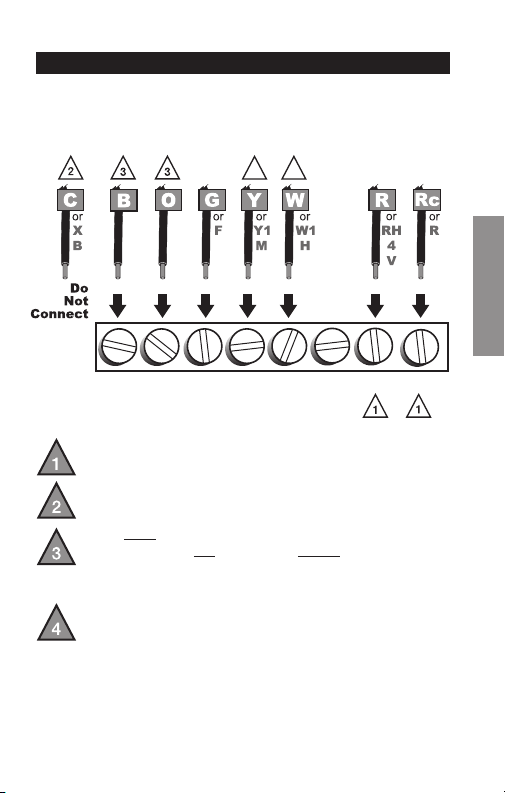
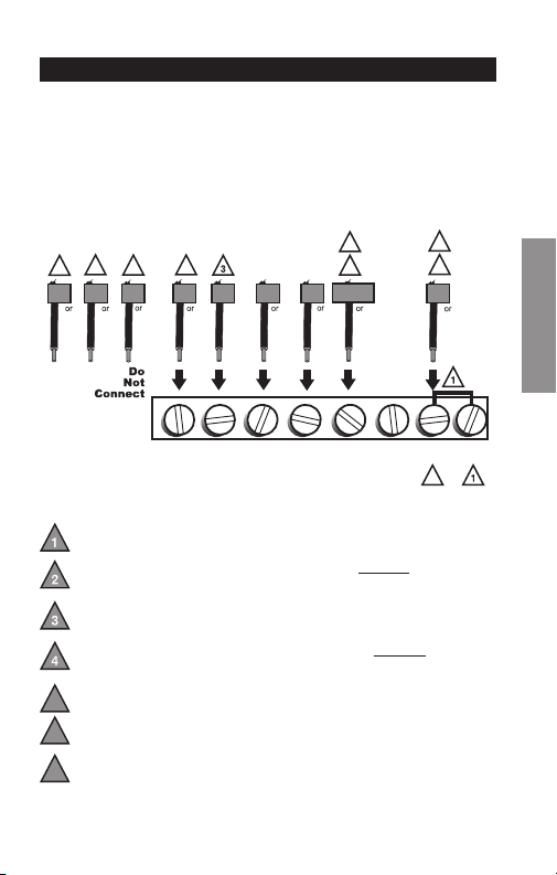
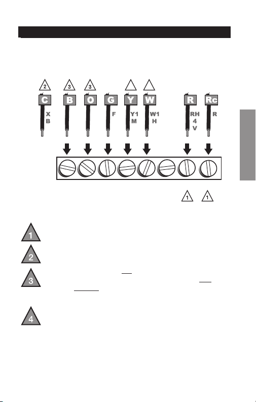
If labels do not match letters on the thermostat, check the
chart below and connect to terminal as shown here (see
notes, below).
Wiring—Conventional System
If wires will be connected to both R and Rc terminals,
remove metal jumper (see page 6).
Do not use
C or X. Wrap bare end of wire with
electrical tape.
If you have a heat pump without auxiliary/backup heat
connect O or B, not both. If you do not have a heat
pump, do not connect B. Wrap bare end of wire with
electrical tape.
Place a jumper (piece of wire) between Y and W/Aux
if you are using a heat pump without auxiliary/backup
heat.
B O G Y
W/
AUX
NOT
USED
R Rc
M32726
44
Advanced Installation Guide
69-2726EF— 01 24
About your new thermostat
SETUPWIRINGASSISTANCETROUBLESHOOTING
M32727
GW/
AUX
OBY
Y
G
O
R
R
Rc
Aux
Wiring—Heat Pump
Connect wires: Heat Pump
1. Match each labeled wire with same letter on new
thermostat.
2. Use a screwdriver to loosen screws, insert wires into
hole under screw, then tighten screws until wire is
secure.
3. Push any excess wire back into the wall opening.
Labels don’t match? See page 25.
Wiring complete, return to Step 7.
RTH2510/RTH2410
25 69-2726EF—01
About your new thermostat
SETUP WIRING ASSISTANCE TROUBLESHOOTING
Wiring—Heat Pump
Alternate wiring (for heat pumps with auxiliary or
backup heat only)
If labels do not match letters on the thermostat, check the
chart below and connect to terminal as shown here (see
notes, below).
Wiring complete, return to Step 7.
Leave metal jumper in place, connecting R & Rc terminals.
If your old thermostat had both V and VR wires, stop now and contact a
qualified contractor for help.
If your old thermostat had separate O and B wires, wrap the B wire in
electrical tape and do not connect.
If your old thermostat had Y1, W1 and W2 wires, stop now and
contact a qualified contractor for help.
Do not use C or X wire. Do not use B wire if you already have O wire.
Wrap bare end of wire with electrical tape.
Do not use L wire. Wrap bare end of wire with electrical tape.
If your old thermostat had E and Aux wires (or alternate wires),
connect both wires to Aux terminal.
5
6
7
M32728
2
7
4
AUX
W
W1
W2
F
B
OG
H
C
RC
V
VR
B
X
R
M
Y1
Y
E
7
X
X2
L
F
6
5
3
2
1
B O G Y
W/
AUX
NOT
USED
R Rc

Advanced Installation Guide
69-2726EF—01 26
Troubleshooting
SETUPWIRINGASSISTANCETROUBLESHOOTING
If you have difficulty with your thermostat, please try the
following suggestions. Most problems can be corrected
quickly and easily.
Display is blank • Makesurefurnacedoorisclosed
securely.
• MakesurefreshAAAalkaline
batteries are correctly installed
(see page 7).
Heating or
cooling system
does not
respond
• SetSystemswitchtoHeat. Make
sure the temperature is set higher
than the Inside temperature.
• SetSystemswitchtoCool. Make
sure the temperature is set lower
than the Inside temperature.
• Checkcircuitbreakerandresetif
necessary.
• Makesureheating&coolingpower
switches are on.
• Makesurefurnacedoorissecurely
closed.
• Wait5minutesforthesystemto
respond.

RTH2510/RTH2410
27 69-2726EF—01
Troubleshooting
SETUP WIRING ASSISTANCE TROUBLESHOOTING
Customer assistance
For assistance with this product, please visit
http://yourhome.honeywell.com or call Honeywell
Customer Care toll-free at 1-800-468-1502.
Temperature
settings do not
change
Make sure heating and cooling
temperatures are set to acceptable
ranges:
• Heat:40°to90°F(4.5°to32°C).
• Cool:50°to99°F(10°to37°C).
“Cool On” or
“Heat On” is
flashing
• Compressor protection feature is
engaged. Wait 5 minutes for the
system to restart safely, without
damage to the compressor.
“Heat On” is
not displayed
• Set the System switch to Heat, and
set the temperature level above the
current room temperature.
“Cool On” is
not displayed
• Set the System switch to Cool, and
set the temperature level below the
current room temperature.

Automation and Control Solutions
Honeywell International Inc.
1985 Douglas Drive North
Golden Valley, MN 55422
http://yourhome.honeywell.com
® U.S. Registered Trademark
© 2013 Honeywell International Inc.
69-2726EF—01 M.S. 03-13
Printed in U.S.A.
CAUTION: To avoid possible compressor damage,
do not run air conditioner if the outside temperature
drops below 50°F (10°C).
MERCURY NOTICE: Do not place your old
thermostat in the trash if it contains mercury in a
sealed tube. Contact the Thermostat Recycling
Corporation at www.thermostat-recycle.org or 800-
238-8192 for information on how and where to
properly and safely dispose of your old thermostat.

69-2726EF-01
Série RTH2510/RTH2410
Thermostat programmable
Guide d’installation rapide

69-2726EF— 01 ii
Identifier le type de système
Ce thermostat est compatible avec les systèmes suivants :
Appareil de chauffage à gaz, mazout ou électrique
Climatiseur central
Système à eau chaude avec ou sans pompe
Système à millivolts
Système de chauffage et de refroidissement central
Thermopompe sans chauffage de secours/auxiliaire
Thermopompe avec chauffage de secours/auxiliaire
Besoin d’aide?
Nous sommes là pour vous aider.
Appeler le 1-800-468-1502
pour obtenir de l’aide avec le
câblage avant de retourner le
thermostat au magasin.
Ce thermostat ne peut pas être utilisé sur les systèmes
à plusieurs étages.

1 69-2726EF—01
1
Couper l’alimentation vers
le système de chauffage/
refroidissement
ou
Coupez
69-2726EF— 01 2
Retirer l’ancien thermostat mais laisser la plaque murale
avec les fils attachés.
Retirer l’ancien thermostat
2
50 60 70 80 F
OFF
AUTO EM. HEAT
EM. HEATAUX. HEAT
50 60 70 80
M33835
Un tube scellé contenant du
mercure est-il présent? Si oui, voir
au dos les consignes de mise au
rebut.
Ancien thermostat
Couvercle
Ne pas retirer la
plaque murale à
ce stade
3 69-2726EF—01
Étiqueter les fils
3
Étiqueter les fils au fur et à mesure qu’ils sont débranchés à
l’aide des étiquettes fournies.
Étiquettes de fils
M28100
M33763
69-2726EF— 01 4
M32731
TO REMOVE WALLPLATE
PULL HERE
Détacher la plaque murale du
nouveau thermostat
4
Retirer la plaque murale du nouveau thermostat et la monter
sur le mur.
Plaque murale
5 69-2726EF—01
Monter la nouvelle plaque murale à l’aide des vis et des
ancrages inclus.
5
Monter la plaque murale
Percer des trous de 3/16 po pour les cloisons sèches.
Percer des trous de 3/32 po pour le plâtre.
W/
Aux
Not
Used
M32714
69-2726EF— 01 6
MF32715
VIS
INSÉRER LES FILS
ET SERRER LES VIS
OUVERTURE
POUR LES FILS
FILS
ÉTIQUETÉS
W/
Aux
W
Y
G
R
Not
Used
Brancher le câblage
6
Il suffit de faire correspondre les étiquettes des fils.
Retirer le cavalier métallique si les fils R et Rc sont présents.
Les étiquettes ne correspondent pas?
Consulter la page 22.
Thermopompe présente dans le système?
Consulter la page 23.
Nous sommes là pour vous aider.
Appeler le 1-800-468-1502 pour obtenir de l’aide
pour le câblage.
7 69-2726EF—01
RTHXXXX
M32707
Installer deux piles alcalines AAA.
Dos du thermostat
7
Installer les piles
69-2726EF— 01 8
Mettre le sélecteur sur le réglage désiré :
Gas or Oil (Gaz ou mazout) : Pour les systèmes de
chauffage à gaz ou à mazout, laisser le sélecteur de
fonctionnement du ventilateur dans la position réglée en
usine (pour les systèmes qui contrôlent le ventilateur lors
d’un appel de chauffage).
Electric or Heat Pump (Thermopompe ou électrique) :
Mettre le sélecteur sur ce réglage pour les systèmes
à thermopompe ou électriques. (Ce réglage concerne
les systèmes qui permettent au thermostat de contrôler
le ventilateur lors d’un appel de chauffage, si un fil de
ventilateur est connecté à la borne G.)
8
Régler le sélecteur de
fonctionnement du ventilateur
RTHXXXX
MF32716
GAS OR OIL
ELECTRIC OR HEAT PUMP
GAS OR OIL
ELECTRIC OR HEAT PUMP

9 69-2726EF—01
W/
Aux
Not
Used
M33592
Heat Off Cool Auto On
Fan
Heat Off Cool
Auto On
Fan
Heat Off Cool Auto On
Fan
Heat Off Cool
Auto On
Fan
Set
Hold
Run
Installer le thermostat sur la plaque murale sur le mur.
9
Installer le thermostat
sur la plaque murale

69 -2726EF— 01 10
Rétablir l’alimentation sur le système
de chauffage/refroidissement.
10
Rétablir l’alimentation
Allumer
ou

11 69-2726EF—01
Si le système est de type :
q Chauffage et refroidissement à étage unique
q Chauffage uniquement ou refroidissement uniquement
Félicitations, vous avez terminé!
Si le système est de type :
q Thermopompe* avec chauffage de secours
Passer à l’installation avancée à la page sui-
vante pour adapter le thermostat au type de sys-
tème présent.
*Thermopompe—un climatiseur qui assure le refroidissement
durant l’été et fonctionne à l’inverse en hiver pour assurer le
chauffage.
Si vous n’êtes pas certain du type de système or pour
d’autres questions, merci de nous appeler au numéro
gratuit 1-800-468-1502.
Ce thermostat fonctionne sur systèmes de 24 V ou 750 mV.
Il ne fonctionnera PAS sur les systèmes conventionnels à
plusieurs étages ou les systèmes à 120/240 V.
11
Si le système est de type…

Installation Avancée
Entrer en mode de configuration du système .................... 13
Modifier les réglages … ..................................................... 14
Type de système ............................................................... 15
Cycle de chauffage … ........................................................ 16
Démarrage précoce … ....................................................... 17
Affichage de la température .............................................. 18
Protection du compresseur … ............................................ 19
Affichage de l’horloge ........................................................ 20
Intervalle de remplacement du filtre .................................. 21
Restaurer le programme par défaut .................................. 22
Système de câblage conventionnel ................................... 23
Câblage de la thermopompe ............................................. 24
Dépannage ........................................................................ 26
Service à la clientèle … ..................................................... 27
RTH2510/RTH2410
13 69-2726EF—01
CONFIGURATION WIRING ASSISTANCE TROUBLESHOOTING
Pour entrer en mode de configuration du système,
appuyer sans relâcher sur les boutons s et t jusqu’à ce
que l’affichage change (environ 5 secondes).
M33593
Heat Off Cool Auto On
Fan
Heat Off Cool
Auto On
Fan
Set
Hold
Run
Entrer en mode de configuration du système
Configuration du système

Guide d’installation avancé
69 - 2726 EF— 01 14
CONFIGURATIONWIRINGASSISTANCETROUBLESHOOTING
1
0
M33594
Set
Hold
Run
Configuration du système
Modifier fonction Modifier réglage
Voir les pages 15 à 21 pour modifier les
réglages de fonction.
Modifier les réglages
Fonction Réglage
1. Appuyer sur s ou t pour modifier le réglage.
2. Appuyer simultanément sur les boutons s et t
pendant une seconde pour passer à la fonction
suivante.
3. Appuyer sur le bouton Run (Marche) pour enregistrer
les modifications et quitter le mode de réglage.
REMARQUE : Si aucun bouton n’est touché pendant
60 secondes dans le menu de configuration, le thermostat
enregistre automatiquement toute modification effectuée
et quitte le menu.
RTH2510/RTH2410
15 69-2726EF—01
CONFIGURATION WIRING ASSISTANCE TROUBLESHOOTING
1
0
M32718
Configuration du système
Fonction 1 : Type de système
0 Chauffage et refroidissement : Chauffage à gaz,
mazout ou électrique avec climatisation centrale ou
thermopompe sans chauffage auxiliaire/de secours.
1 Thermopompe avec chauffage
auxiliaire/de secours : Le compresseur extérieur
fournit le chauffage et le refroidissement.
Appuyer sur le bouton s ou t pour sélectionner le type
de système de chauffage/refroidissement utilisé dans la
maison.
Appuyer
sur pour
modifier le
réglage.
Une fois terminé,
appuyer sur s et
t pour passer
à la fonction
suivante.
MF33591
ET
OU
Guide d’installation avancé
69 -2726EF— 01 16
À propos du nouveau thermostat
CONFIGURATIONWIRINGASSISTANCETROUBLESHOOTING
5
5
M32720
Configuration du système
Appuyer sur le bouton s ou t pour sélectionner le sys-
tème de chauffage et optimiser son fonctionnement.
Fonction 5 : Cycle de chauffage
5 Appareil de chauffage à gaz ou à mazout : Utiliser
ce réglage si l’appareil de chauffage est un modèle
à gaz ou à mazout standard et efficace à moins de
90 %.
6 Appareil de chauffage électrique : Utiliser ce
réglage pour tout type de système de chauffage
électrique.
3 Système à eau chaude ou appareil de chauffage à
gaz haute efficacité : Utiliser ce réglage si le système
est un système à eau chaude ou un appareil de
chauffage à gaz d’une efficacité supérieure à 90 %.
2 Système à gravité ou à vapeur à gaz/mazout :
Utiliser ce réglage si le système de chauffage est à
vapeur ou à gravité.
Appuyer
sur pour
modifier le
réglage.
Une fois terminé,
appuyer sur s et
t pour passer
à la fonction
suivante.
MF33591
ET
OU
RTH2510/RTH2410
17 69-2726EF—01
À propos du nouveau thermostat
CONFIGURATION WIRING ASSISTANCE TROUBLESHOOTING
13
1
M32721
Configuration du système
Appuyer sur le bouton s ou t pour sélectionner le
démarrage précoce.
Fonction 13 : Démarrage précoce
1 Marche
0 Arrêt
Le démarrage précoce permet d’activer le
chauffage ou le refroidissement avant l’heure
programmée pour que la température souhaitée
soit atteinte à l’heure indiquée. Il suffit de
programmer les heures et la température
désirées. Le thermostat enclenche le chauffage
ou le refroidissement à l’avance pour que la
température désirée soit atteinte au moment
voulu.
Appuyer
sur pour
modifier le
réglage.
Une fois terminé,
appuyer sur s et
t pour passer
à la fonction
suivante.
MF33591
ET
OU
Guide d’installation avancé
69 -2726EF — 01 18
CONFIGURATIONWIRINGASSISTANCETROUBLESHOOTING
Configuration du système
Fonction 14 : Affichage de la température
0 Affichage de température en Fahrenheit (°F)
1 Affichage de température en Celsius (°C)
Appuyer sur le bouton s et t pour sélectionner l’affiche
de la température en Fahrenheit ou en Celsius.
14
0
M32722
Appuyer
sur pour
modifier le
réglage.
Une fois terminé,
appuyer sur s et
t pour passer
à la fonction
suivante.
MF33591
ET
OU

RTH2510/RTH2410
19 69-2726EF—01
CONFIGURATION WIRING ASSISTANCE TROUBLESHOOTING
Configuration du système
Fonction 15 : Protection du compresseur
1 Marche
0 Arrêt
Appuyer sur le bouton s et t pour sélectionner les
réglages de protection du compresseur.
Protection du compresseur : Cette fonction force
le compresseur à attendre 5 minutes avant le
redémarrage, pour éviter les dommages de l’équipement.
Durant la période d’attente, le message « Cool On »
(refroidissement en marche) ou « Heat On » (chauffage
en marche) s’affiche sur l’écran.
15
1
M32723
Appuyer
sur pour
modifier le
réglage.
Une fois terminé,
appuyer sur s et
t pour passer
à la fonction
suivante.
MF33591
ET
OU
Guide d’installation avancé
69-2726EF— 01 20
CONFIGURATIONWIRINGASSISTANCETROUBLESHOOTING
Configuration du système
Fonction 20 : Affichage de l’horloge
0 Format 12 heures
1 Format 24 heures
Appuyer sur le bouton s et t pour sélectionner
l’affichage de l’horloge.
20
0
M32724
Appuyer
sur pour
modifier le
réglage.
Une fois terminé,
appuyer sur s et
t pour passer
à la fonction
suivante.
MF33591
ET
OU
RTH2510/RTH2410
21 69-2726EF—01
CONFIGURATION WIRING ASSISTANCE TROUBLESHOOTING
Configuration du système
Fonction 21 : Intervalle de remplacement du filtre
21
0
M33631
Appuyer
sur pour
modifier le
réglage.
Une fois terminé,
appuyer sur s et
t pour passer
à la fonction
suivante.
MF33591
ET
OU
0 Arrêt
1 30 jours
2 90 jours
3 6 mois
4 9 mois
5 1 an
Appuyer sur le bouton s et t pour sélectionner
Intervalle de remplacement du filtre.
Guide d’installation avancé
69-2726EF— 01 22
À propos du nouveau thermostat
CONFIGURATIONWIRINGASSISTANCETROUBLESHOOTING
Configuration du système
Fonction 40 : Restaurer le programme par défaut
0 Arrêt
1 Marche - Les réglages par défaut du programme sont
indiqués dans le manuel de fonctionnement.
Appuyer sur le bouton s et t pour restaurer le
programme par défaut.
MF33595
OU
Appuyer
sur pour
modifier le
réglage.
Une fois terminé,
appuyer sur
Run (marche)
pour quitter et
enregistrer les
changements.
40
0
M32725
RTH2510/RTH2410
23 69-2726EF—01
À propos du nouveau thermostat
SETUP CÂBLAGE ASSISTANCE TROUBLESHOOTING
Si les étiquettes ne correspondent pas aux lettres sur
le thermostat, consulter le tableau ci-dessous et faire le
branchement aux bornes comme illustré ici (voir les notes
ci-dessous).
Câblage—Système conventionnel
SileslsvontêtreconnectésauxbornesR et Rc,
retirer le cavalier métallique (voir page 6).
Ne pas utiliser C ou X.Enroulerl’extrémiténuedesls
de ruban électrique.
Si une thermopompe est installée sans chauffage
auxiliaire/de secours, connecter O ou B mais pas les
deux. Si aucune thermopompe n’est présente, ne
pas connecter B. Appliquer du ruban électrique sur
l’extrémitédénudéedul.
Placeruncavalier(morceaudel)entreY et W si
une pompe thermique est utilisée sans chauffage
auxiliaire/de secours.
B O G Y
W/
AUX
NOT
USED
R Rc
ou
Ne
pas
connecter
ou
ou ou
MF32726
4
ou
4
ou
Guide d’installation avancé
69-2726EF— 01 24
À propos du nouveau thermostat
SETUPCÂBLAGEASSISTANCETROUBLESHOOTING
MF32727
NOT
USED
G
W/
AUX
OBY
Y
G
O
R
R
Rc
Aux
Câblage—Thermopompe
Brancher les fils : thermopompe
1. Faire correspondre chaque fil étiqueté avec la même
lettre sur le nouveau thermostat.
2. Utiliser un tournevis pour desserrer les vis, insérer les
fils dans l’orifice sous la vis, puis serrer les vis pour
maintenir les fils.
3. Repousser le fil en excès dans l’ouverture du mur.
Les étiquettes ne correspondent pas? Consulter la
page 25.
Câblage terminé, revenir à l’étape 7.

RTH2510/RTH2410
25 69-2726EF—01
À propos du nouveau thermostat
SETUP CÂBLAGE ASSISTANCE TROUBLESHOOTING
Câblage—Thermopompe
Autre option de câblage (pour les thermopompes avec
chauffage auxiliaire ou de secours uniquement)
Si les étiquettes ne correspondent pas aux lettres sur
le thermostat, consulter le tableau ci-dessous et faire le
branchement aux bornes comme illustré ici (voir les notes
ci-dessous).
Câblage terminé, revenir à l’étape 7.
Laisser le cavalier métallique en place en connectant les bornes R
et Rc.
Si l’ancien thermostat est muni de fils V et VR, s’arrêter immédiatement
et contacter un installateur qualifié pour obtenir de l’aide.
Si l’ancien thermostat a des fils O et B séparés, enrouler le fil B dans
du ruban électrique sans le brancher.
Si l’ancien thermostat est muni de fils Y1, W1 et W2, s’arrêter
immédiatementet contacter un installateur qualifié pour obtenir de
l’aide.
Ne pas utiliser les fils C ou X. Ne pas utiliser le fil B si un fil O est déjà
présent. Enrouler l’extrémité nue du fil avec du ruban électrique.
Ne pas utiliser le fil L. Enrouler l’extrémité nue du fil avec du ruban
électrique.
Si l’ancien thermostat a des fils E et Aux (ou d’autres fils), brancher
les deux fils à la borne Aux.
5
6
7
MF32728
2
7
4
AUX
W
W1
W2
F
B
OG
H
Ne
pas
connecter
C
RC
V
VR
B
X
R
M
Y1
Y
E
7
X
X2
L
F
6
5
3
2
1
B O G Y
R Rc
W/
AUX
NOT
USED
ou
ou ou ou ou ou ou ou

Guide d’installation avancé
69-2726EF—01 26
Assistance à la clientèle
SETUPWIRINGASSISTANCEDÉPANNAGE
Dépannage
En cas de difficultés avec le thermostat, essayer les solu-
tions suivantes. La plupart des problèmes peuvent être
réglés rapidement et facilement.
Rien n’apparaît
à l’écran
• S’assurerquelaportedel’appareil
de chauffage est bien fermée.
• S’assurerquedespilesalcalinesAAA
neuves sont correctement installées
(voir page 7).
Le système de
chauffage ou de
refroidissement
ne fonctionne
pas
• RéglerlesélecteursurHeat
(chauffage). S’assurer que le point
de consigne est plus élevé que la
température ambiante.
• RéglerlesélecteursurCold
(refroidissement). S’assurer que le
point de consigne est moins élevé
que la température intérieure.
• Vérifierledisjoncteuretleréinitialiser
si nécessaire.
• S’assurerquelessélecteursde
chauffage et de refroidissement sont
sur marche.
• S’assurerquelaportedel’appareil
de chauffage est bien fermée.
• Attendre5minutesquelesystème
réponde.

RTH2510/RTH2410
27 69-2726EF—01
Assistance à la clientèle
SETUP WIRING ASSISTANCE DÉPANNAGE
Service à la clientèle
Pour obtenir de l’aide avec ce produit, consulter
http://yourhome.honeywell.com ou appeler le centre du
service à la clientèle de Honeywell au numéro gratuit
1-800-468-1502.
Les réglages de la
température
ne changent pas
S’assurer que les températures de
chauffage et de refroidissement sont
réglées dans les plages permises :
• Chauffage:4,5à32°C(40à90°F).
• Refroidissement:10à37°C
(50 à 99 °F).
« Cool On »
(refroidissement sur
marche) ou « Heat
On » (chauffage sur
marche) clignote
• La fonction de protection du
compresseur est activée. Attendre 5
minutes que le système se remette
en marche en toute sécurité sans
endommager le compresseur.
« Heat On »
(chauffage sur
marche) n’apparaît
pas à l’écran
• Mettre le sélecteur du système sur
Heat (chauffage) et régler le niveau
de température à une température
supérieure à la température
ambiante.
« Cool On »
(refroidissement
sur marche)
n’apparaît pas à
l’écran
• Mettre le sélecteur du système
sur Cool (refroidissement) et
régler le niveau de température
à une température inférieure à la
température ambiante.
Dépannage
Solutions de régulation et d’automatisation
Honeywell International Inc.
1985 Douglas Drive North
Golden Valley, MN 55422
http://yourhome.honeywell.com
® Marque de commerce déposée aux É.-U.
© 2013 Honeywell International Inc.
69-2726EF—01 M.S. 03-13
Imprimé aux États-Unis
MISE EN GARDE : Pour éviter d’endommager le
compresseur, ne pas faire fonctionner le climatiseur
si la température extérieure est inférieure à 10 °C
(50 °F).
AVIS RELATIF AU MERCURE : Ne pas jeter
l’ancien thermostat dans la poubelle s’il contient
du mercure dans un tube scellé. Contacter
le Thermostat Recycling Corporation à www.
thermostat-recycle.org ou le 800-238-8192 pour
obtenir de l’information sur la façon et l’endroit
appropriés de se débarrasser du vieux thermostat.