RPLS530A/RPLS531A 1/6
RPLS530A/RPLS531A
Installation and User Guide
Programmable Wall Switch
The RPLS530A/RPLS531A switch can be used in a single-pole or 3-way
installation with the following types of lighting:
• Incandescent
• Halogen
• Low-voltage halogen with transformer
• Fluorescent
The
RPLS530A/RPLS531A
switch cannot be used with a load below 40
W, a load above 500 W or a motor.
Cut power at the circuit breaker to avoid electric shock.
Remove the existing switch. (For a 3-way installation, identify and
label the wire that is connected to the “common” screw.)
Install the new switch (refer to the appropriate section below).
Apply power at the circuit breaker.
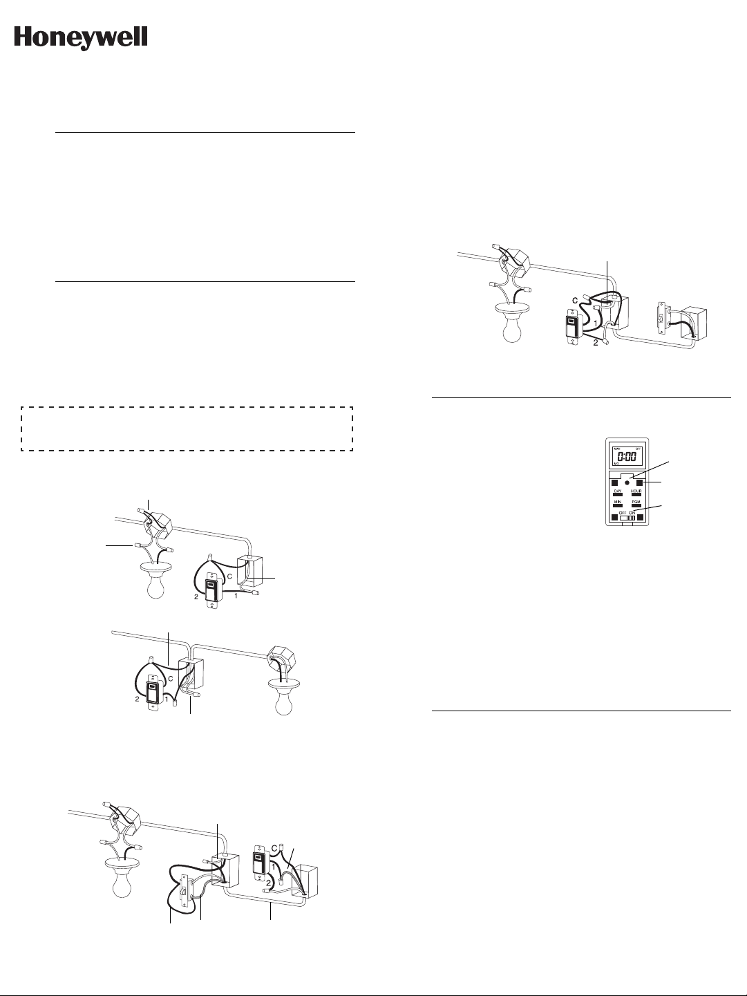
SINGLE-POLE INSTALLATION
Connect wires "2" and "C" of the RPLS530A/RPLS531A to the line
(120 V) wire.
EXISTING 3-WAY INSTALLATION
Connect wire "C" of the RPLS530A/RPLS531A to the "common" wire,
identified when removing the old switch. Connect the other two
RPLS530A/RPLS531A wires to the two remaining wires.
At the other 3-way switch, connect the jumper wire between the "com-
mon" screw and the screw where wire "1" of the RPLS530A/RPLS531A
is connected.
NEW 3-WAY INSTALLATION
The jumper wire is not required in this installation. A single-pole switch
can be used as the other switch in a 3-way installation.
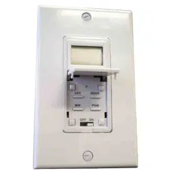
Pry the switch door open from the
bottom using a small screwdriver.
Ensure the ON/OFF selector is set to
ON.
Reset the switch using a paper clip.
0:00 and MO will flash.
If the display is blank:
• Ensure the ON/OFF selector is prop-
erly engaged in the ON position. Push it to the right using a small
screwdriver.
• If the programmable switch controls a lamp equipped with a built-in
On/Off switch, ensure the lamp switch is set to On.
• Ensure the light bulb is not burned out and is tightly screwed in its socket.
EXISTING 3-WAY INSTALLATION
If either switch does not work properly, rewire the jumper between the
"common" screw and the other screw.
WARNING: Before replacing the light bulb, place the ON/OFF selector in
the OFF position. Failure to do so might damage the switch.
NOTE: The switch displays the time in 24-hour format by default or fol-
lowing a reset.
To change to 12-hour format (or vice versa), proceed as follows:
a) Press one of the control buttons to ensure the MAN or AUTO
indicator is displayed.
b) Press the MIN and HOUR buttons simultaneously and brieftly
(0:00 display = 24-hour, 12:00 display = 12-hour ).
Set the time using the HOUR and MIN buttons. If you have selected
the 12-hour format, ensure that PM appears on the screen when an
afternoon time is displayed.
Set the day by using the DAY button.
Press one of the control buttons or close the switch door to return to
normal operation.
Applications
1.
Installation
2.
NOTE A:
The white wire is not the neutral wire but the wire going to the load.
Line
Neutral
See NOTE A
120 VAC
Line
Neutral
120 VAC
Red
120 VAC
Jumper
Red
3-wire cable
See NOTE A
Power-On
3.
Setting the Clock
4.
120 VAC
See NOTE A
Control (4)
Reset
On/Off selector
69-2458EFS-01_400-032-005-B (TI032-3W_RPLS530A) USA print at 90%.book Page 1 Tuesday, May 18, 2010 10:34 AM
RPLS530A/RPLS531A 2/6
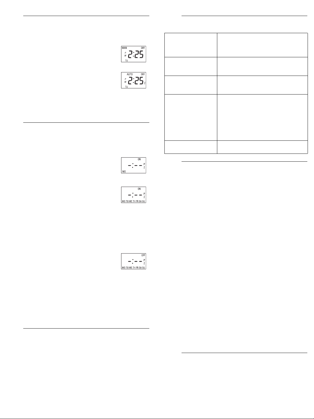
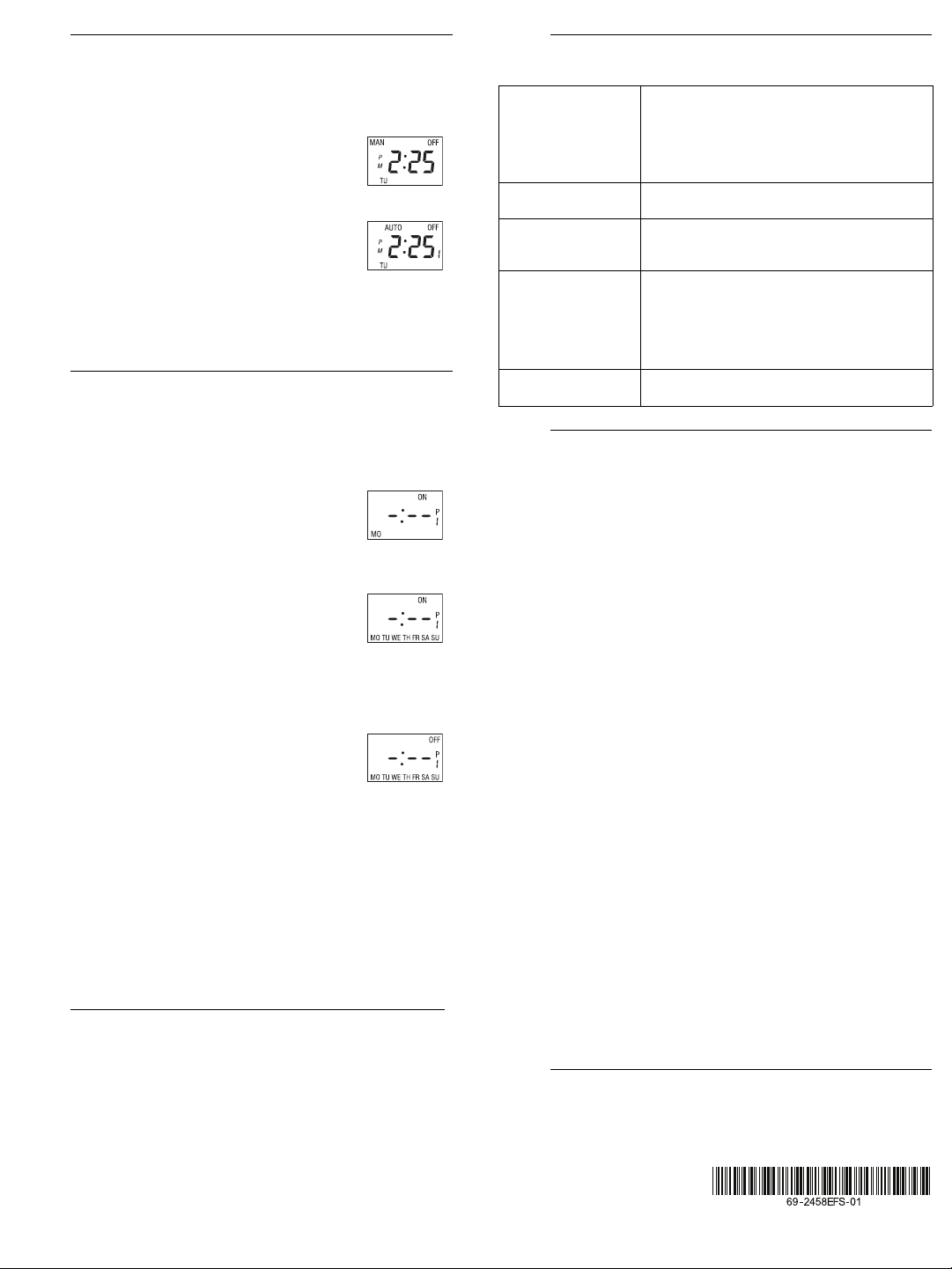
The programmable switch has 2 operating modes: manual (MAN) and
automatic (AUTO).
To switch mode, press the switch door for 3 seconds.
Manual Mode
The programmable switch operates as a regular switch.
Briefly press the switch door to turn the lights On or Off.
The mode (MAN) and state (ON or OFF) are displayed.
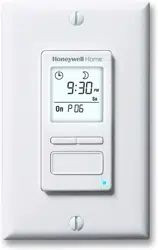
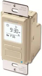
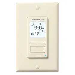
Automatic Mode
The programmable switch follows the programmed
schedule. The mode (AUTO), state (ON or OFF) and
current program number are displayed.
To temporarily override the programmed schedule, press the switch door.
The new state (ON or OFF) will flash to show that this state is temporary.
The override remains in effect until you press the switch door again or
until the beginning of the next program.
You can set up to 7 programs. To set a program, you need to enter its
start time (ON) and its end time (OFF).
Pry the switch door open using a small screwdriver.
Press the PGM button to display a program and its
On or Off time. For example, when you first press
PGM, program number 1 (P1) and its On time
(ON) will appear.
-:-- will appear instead of the
time if the program is not set (inactive).
Press the DAY button to select the day to which
you want to apply the program.
NOTE: If you want to apply the program to every
day of the week, press DAY until all the days are
displayed. (This still counts as 1 program, not 7)
Press the HOUR and MIN buttons to set the ON time (time when
you want the lights to turn on). If you have selected the 12-hour
format, ensure that PM appears on the screen when an afternoon
time is displayed.
After you have programmed the ON time, press the PGM button to
display the OFF time (time when you want the lights to turn off).
Repeat steps 3 through 5 to program the OFF
time. If the program ON time is set for every day of
the week, the program OFF time will automatically
be set for every day.
To set another program, repeat steps 2 through 6.
Programs that are not set will remain inactive.
Press one of the control buttons or close the switch door to return to
normal operation.
Clearing a Program
Press the PGM button until the desired program is selected. Hold the
PGM button for 3 seconds.
-:-- appears when the program is erased.
Supply: 120 VAC, 50 / 60 Hz
Minimum load: 40 watts
Maximum load: 500 watts
Operating temperature range: 5°F to 122°F (-15°C to 50°C)
Storage temperature range: -4°F to 122°F (-20°C to 50°C)
Power outage: The programs are protected by a rechargeable battery.
The screen is blank during the power outage.
Certifications: CSA & UL
Honeywell warrants this product, excluding battery, to be free from defects in the
workmanship or materials, under normal use and service, for a period of one (1)
year from the date of purchase by the consumer. If at any time during the warranty
period the product is determined to be defective or malfunctions, Honeywell shall
repair or replace it (at Honeywell's option).
If the product is defective,
(i) return it, with a bill of sale or other dated proof of purchase, to the place from
which you purchased it, or
(ii) call Honeywell Customer Care at 1-800-468-1502. Customer Care will make
the determination whether the product should be returned to the following
address: Honeywell Return Goods, Dock 4 MN10-3860, 1885 Douglas Dr N,
Golden Valley, MN 55422, or whether a replacement product can be sent to
you.
This warranty does not cover removal or reinstallation costs. This warranty shall
not apply if it is shown by Honeywell that the defect or malfunction was caused by
damage which occurred while the product was in the possession of a consumer.
Honeywell's sole responsibility shall be to repair or replace the product within the
terms stated above. HONEYWELL SHALL NOT BE LIABLE FOR ANY LOSS OR
DAMAGE OF ANY KIND, INCLUDING ANY INCIDENTAL OR CONSEQUENTIAL
DAMAGES RESULTING, DIRECTLY OR INDIRECTLY, FROM ANY BREACH OF
ANY WARRANTY, EXPRESS OR IMPLIED, OR ANY OTHER FAILURE OF THIS
PRODUCT. Some states do not allow the exclusion or limitation of incidental or
consequential damages, so this limitation may not apply to you.
THIS WARRANTY IS THE ONLY EXPRESS WARRANTY HONEYWELL MAKES
ON THIS PRODUCT. THE DURATION OF ANY IMPLIED WARRANTIES,
INCLUDING THE WARRANTIES OF MERCHANTABILITY AND FITNESS FOR A
PARTICULAR PURPOSE, IS HEREBY LIMITED TO THE ONE-YEAR DURATION
OF THIS WARRANTY. Some states do not allow limitations on how long an implied
warranty lasts, so the above limitation may not apply to you.
This warranty gives you specific legal rights, and you may have other rights which
vary from state to state.
If you have any questions concerning this warranty, please write Honeywell Cus-
tomer Relations, 1985 Douglas Dr, Golden Valley, MN 55422 or call
1-800-468-1502. In Canada, write Retail Products ON15-02H, Honeywell Limited/
Honeywell Limitée, 35 Dynamic Drive, Scarborough, Ontario M1V4Z9.
If you have any questions about your light switch, go to
http://yourhome.honeywell.com, or call Honeywell Customer Care
toll-free at 1-800-468-1502.
Selecting the Operating Mode
5.
Programming
6.
Technical Specifications
7.
Troubleshooting
8.
Blank display • Verify circuit breaker at main panel.
• Verify if light bulb is burned out
• Ensure the ON/OFF selector is at ON.
• Reset the switch using a paper clip.
Faded or irregular
display
• Load is less than 40 W
• Ambient temperature is below freezing
point
Cannot switch between
24-hour format and
12-hour format
First, press one of the control buttons so
that MAN or AUTO appears on display.
Programs do not run as
expected
• Make sure the switch is properly pro-
grammed.
• Note that
-:-- indicates an inactive pro-
gram, 00:00 indicates midnight.
• If the switch has been configured for
12-hour format, check that PM appears on
the left side of the screen when an after-
noon time is displayed.
The metal plate is hot This is normal with high loads (maximum of
500 W).
Warranty
9.
Customer Assistance
10.
69-2458EFS-01_400-032-005-B (TI032-3W_RPLS530A) USA print at 90%.book Page 2 Tuesday, May 18, 2010 10:34 AM
RPLS530A/RPLS531A 3/6
RPLS530A/RPLS531A
Mode d’installation et d’emploi
Interrupteur mural programmable
L’interrupteur RPLS530A/RPLS531A peut être utilisé aussi bien pour une
installation unipolaire que pour une installation à 3 voies avec les types
d’éclairage suivants :
• Incandescent
• Halogène
• Halogène basse tension avec transformateur
• Fluorescent
Le RPLS530A/RPLS531A ne peut être utilisé avec une charge infé-
rieure à 40 W , une charge supérieure à 500 W ou un moteur.
Mettre le circuit hors tension à partir du disjoncteur afin d'éviter tout
risque de choc électrique.
Enlever l’interrupteur existant (pour une installation à 3 voies, identi-
fier et marquer le fil relié à la borne «commun»).
Installer le nouvel interrupteur (voir la section appropriée ci-des-
sous).
Remettre le circuit sous tension à partir du disjoncteur.
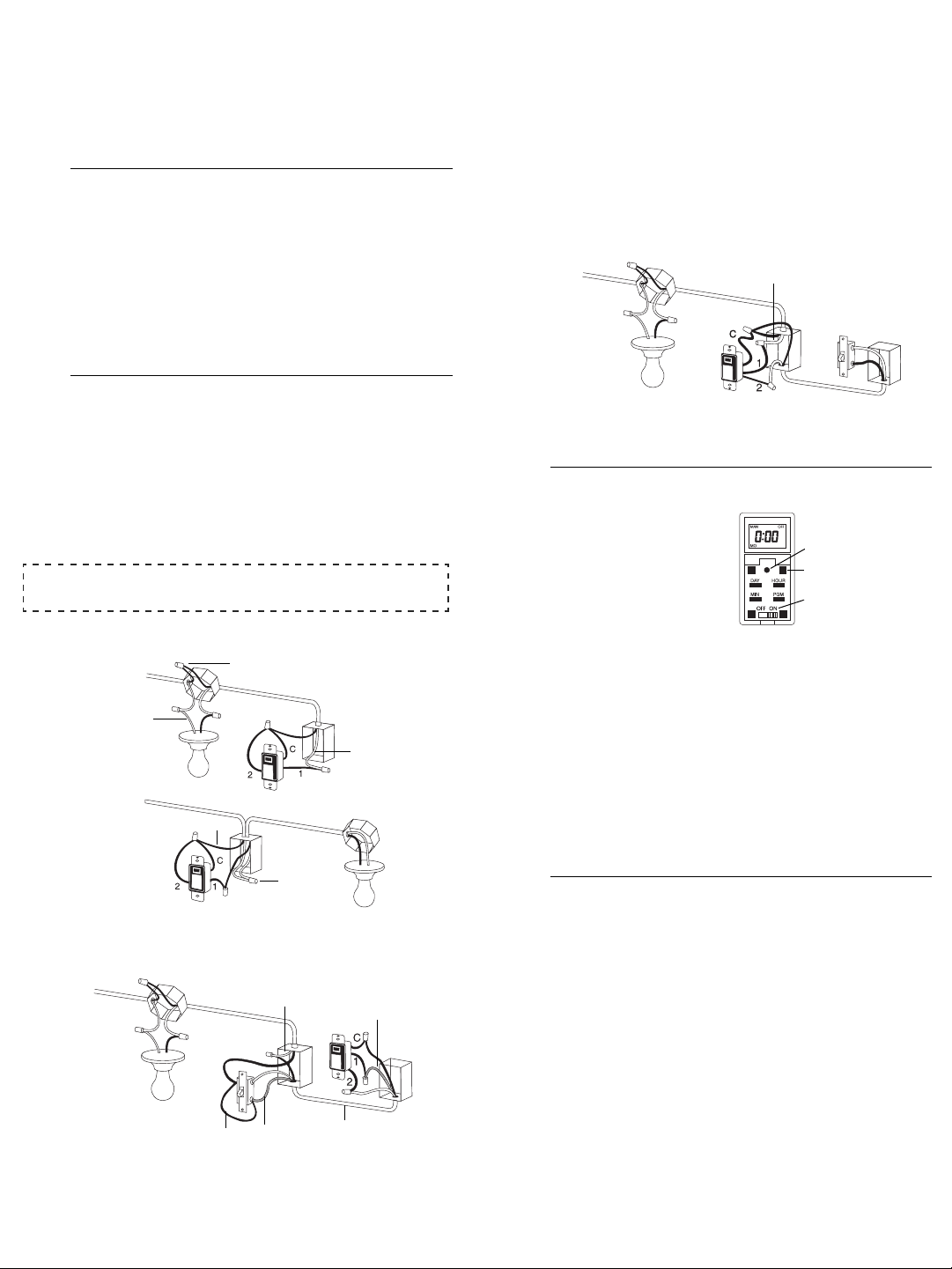
INSTALLATION UNIPOLAIRE
Relier les fils «2» et «C» du RPLS530A/RPLS531A à la ligne 120 Vca.
INSTALLATION EXISTANTE À 3 VOIES
Relier le fil «C» du RPLS530A/RPLS531A au fil «commun» que vous
avez identifié lorsque vous avez enlevé l’ancien interrupteur. Relier les
deux autres fils du RPLS530A/RPLS531A aux deux fils restants.
Pour l’autre interrupteur à 3 voies, relier le fil de raccord (fourni) entre la
borne «commun» et la borne sur laquelle le fil «1» du RPLS530A/RPLS531A
est branché.
NOUVELLE INSTALLATION À 3 VOIES
Le fil de raccord n’est pas requis dans cette installation. Dans le cas
d’une installation à 3 voies, l’autre interrupteur peut être un interrupteur
unipolaire.
Soulevez le bas du couvercle de
l’interrupteur à l’aide d’un petit
tournevis.
S’assurer que le sélecteur ON/
OFF est placé à ON.
Réinitialiser l’interrupteur à
l’aide d’un trombone. 0:00
clignotera à l’écran.
Si rien n’est affiché à l’écran :
• S’assurer que le sélecteur ON/OFF est bien mis à la position ON. Le
placer bien à droite à l’aide d’un petit tournevis.
• Si l’interrupteur commande une lampe munie d’un interrupteur inté-
gré, placer son interrupteur à «Marche» (On).
• S’assurer que l’ampoule n’est pas brûlée et est bien vissée.
INSTALLATION EXISTANTE À 3 VOIES
Si l’un ou l’autre des interrupteurs ne fonctionne pas, rebrancher le fil de
raccord entre la borne «commun» et l’autre borne.
MISE EN GARDE : Avant de remplacer l'ampoule, placer le sélecteur
ON/OFF (marche/arrêt) à la position OFF, faute de quoi l’interrupteur
risque d’être endommagé.
NOTA : L’interrupteur affiche l’heure en format 24 heures par défaut ou
après une réinitialisation.
Pour basculer entre le format 12 heures et le format 24 heures, pro-
céder comme suit :
a) Appuyer sur l’une des touches de contrôle afin de s’assurer que
l’indicateur MAN ou AUTO est affiché.
b) Appuyer simultanément et brièvement sur les touches
MIN
et
HOUR
(affichage
0:00
= 24 heures; affichage
12:00
= 12 heu-
res).
Régler l’heure à l’aide des touches HOUR et MIN. Si le format 12
heures est sélectionné, s’assurer que PM apparaît lorsque l’heure
de l’après-midi est affichée.
Régler le jour à l’aide de la touche DAY.
Appuyer sur une touche de contrôle ou replacer le couvercle de
l’interrupteur.
Applications
1.
Installation
2.
NOTE A:
Le fil blanc n’est pas le fil neutre, mais un fil raccordé à la charge.
120 Vca
Voir la NOTE A
neutre
ligne
neutre
ligne
120 Vca
120 Vca
Voir la NOTE A
rouge
câble trifilaire
rouge
raccord
Démarrage
3.
Régler l’horloge
4.
120 Vca
Voir la NOTE A
réinitialisation
touche de contrôle (4)
sélecteur On/Off
69-2458EFS-01_400-032-005-B (TI032-3W_RPLS530A) USA print at 90%.book Page 3 Tuesday, May 18, 2010 10:34 AM
RPLS530A/RPLS531A 4/6
L’interrupteur a 2 modes de fonctionnement : manuel (MAN) et automatique
(AUTO). Pour changer de mode, appuyer sur l’interrupteur pendant 3 secon-
des.
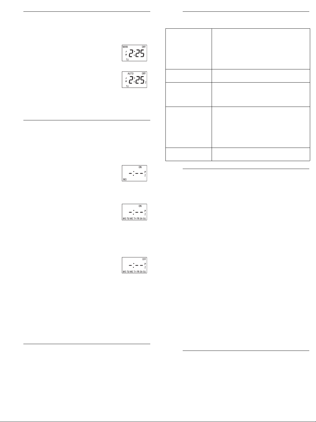
Mode manuel
L’interrupteur programmable fonctionne comme un inter-
rupteur conventionnel. Appuyer sur l’interrupteur pour allu-
mer ou éteindre la lumière. Le mode (MAN) et l’état de
marche/arrêt (ON ou OFF) sont affichés.
Mode automatique
L’interrupteur suit l’horaire programmé. Le mode (AUTO),
l’état de marche/arrêt (ON ou OFF) et le numéro du pro-
gramme en cours sont affichés.
Pour déroger temporairement à l’horaire programmé, appuyer sur l’interrup-
teur. Le nouvel état (ON ou OFF) clignotera pour indiquer que l’état est tem-
poraire. La dérogation reste active jusqu’à ce qu’on appuie de nouveau sur
l’interrupteur ou jusqu’au début du prochain programme.
Vous pouvez enregistrer jusqu'à 7 programmes. Pour enregistrer un
programme, vous devez régler l’heure du début (ON) et l’heure de la fin
(OFF).
Soulevez le bas du couvercle de l’interrupteur à l’aide d’un petit
tournevis.
Appuyer sur la touche PGM pour afficher un
programme et l’heure du début (ON) du programme
ou l’heure de la fin (OFF) du programme. Par
exemple, lorsque vous appuyez sur PGM pour la
première fois, le programme 1 (P1) et l’heure du
début (ON) sont affichés. -:-- est affiché au lieu de l’heure si le
programme n’est pas enregistré (c.-à-d. s’il est inactif).
Appuyer sur DAY pour sélectionner le jour du
programme.
NOTA
: Si vous désirez que le programme se répète
tous les jours, appuyer sur
DAY
jusqu’à ce que les 7
jours soient affichés. (Ceci compte pour 1 programme et non 7.)
Appuyer sur HOUR et MIN pour régler l’heure du début du programme
(ON) (heure à laquelle vous voulez que la lumière s'allume). Si le format
d’affichage 12 heures est utilisé, s’assurer que la mention PM apparaît
lorsque l’heure de l’après-midi est affichée.
Une fois l’heure du début du programme enregistrée,
appuyer de nouveau sur PGM pour afficher l’heure de
la fin du programme.
Répéter les étapes 3 à 5 pour régler la fin du
programme (OFF) (l'heure à laquelle vous voulez que
la lumière s’éteigne).
Pour régler un autre programme, répéter les étapes 2 à 6. Les
programmes non réglés resteront inactifs.
Appuyer sur une touche de contrôle ou replacer le couvercle de
l’interrupteur.
Effacer un programme
Appuyer sur la touche PGM jusqu’à ce que le programme désiré soit
sélectionné. Appuyer ensuite sur la touche PGM pendant 3 secondes. L'écran
affiche
-:-- lorsque le programme est effacé.
Alimentation : 120 Vca, 50 / 60 Hz
Charge : 40 W minimum, 500 W maximum
Température de fonctionnement : -15 °C à 50 °C (5 °F à 122 °F)
Température d’entreposage : -20 °C à 50 °C (-4 °F à 122 °F)
Panne de courant : L'interrupteur est muni d'une pile rechargeable pour
sauvegarder vos programmes lors d’une panne de courant. Cependant,
l'écran reste éteint durant la panne.
Certifications : CSA & UL
Honeywell garantit ce produit, à l'exception des piles, contre tout vice de fabrication ou
de matière dans la mesure où il en est fait une utilisation et un entretien convenables, et
ce, pour un (1) an à partir de la date d'achat par le consommateur. En cas de
défectuosité ou de mauvais fonctionnement pendant la période de garantie, Honeywell
remplacera ou réparera le produit (au gré de Honeywell).
Si le produit est défectueux,
(i) le retourner, accompagné d'une preuve d'achat indiquant la date d'achat, à l’endroit
où il a été acheté, ou
(ii) s'adresser au Service à la clientèle de Honeywell en composant le 1-800-468-
1502. Le Service à la clientèle déterminera alors si le produit doit être retourné à
l'adresse suivante : Honeywell Return Goods, Dock 4 MN10-3860, 1885 Douglas
Dr N, Golden Valley, MN 55422, ou si un produit de remplacement peut vous être
expédié.
La présente garantie ne couvre pas les frais de retrait ou de réinstallation. La présente
garantie ne s'appliquera pas s'il est démontré que la défectuosité ou le mauvais
fonctionnement est dû à un endommagement du produit alors que le consommateur
l'avait en sa possession.
La responsabilité de Honeywell se limite à réparer ou à remplacer le produit
conformément aux modalités susmentionnées. HONEYWELL N'EST EN AUCUN CAS
RESPONSABLE DES PERTES OU DOMMAGES, Y COMPRIS LES DOMMAGES
INDIRECTS OU ACCESSOIRES DÉCOULANT DIRECTEMENT OU INDIRECTEMENT
D'UNE VIOLATION QUELCONQUE D'UNE GARANTIE, EXPRESSE OU TACITE,
APPLICABLE AU PRÉSENT PRODUIT NI DE TOUTE AUTRE DÉFECTUOSITÉ DU
PRÉSENT PRODUIT. Certaines provinces ne permettent pas l'exclusion ou la restriction
des dommages indirects et, par conséquent, la présente restriction peut ne pas
s'appliquer.
LA PRÉSENTE GARANTIE TIENT LIEU DE TOUTES LES AUTRES GARANTIES,
EXPRESSES OU TACITES, ET LES GARANTIES DE VALEUR MARCHANDE ET DE
CONFORMITÉ À UNE FIN PARTICULIÈRE SONT PAR LES PRÉSENTES EXCLUES
APRÈS LA PÉRIODE DE UN AN DE LA PRÉSENTE GARANTIE Certaines provinces ne
permettent pas de limiter la durée des garanties tacites et, par conséquent, la présente
limitation peut ne pas s'appliquer.
La présente garantie donne au consommateur des droits légaux spécifiques et peut-être
certains autres droits qui peuvent varier d'une province à l'autre.
Pour toute question concernant la présente garantie, prière d'écrire au Service à la
clientèle de Honeywell à l'adresse suivante : Honeywell Customer Relations, 1985
Douglas Drive, Golden Valley, MN 55422, ou encore composer le 1-800-468-1502. Au
Canada, prière de s'adresser au service des Produits de détail, Honeywell Limited/
Honeywell Limitée, 35, Dynamic Drive, Scarborough (Ontario) M1V 4Z9.
Si vous avez des questions sur le fonctionnement de votre interrupteur
programmable, veuillez consulter
http://yourhome.honeywell.com
,
ou vous adresser au Service à la clientèle de Honeywell en composant
sans frais le
1-800-468-1502
.
Modes de fonctionnement
5.
Programmation
6.
Fiche technique
7.
Dépannage
8.
Écran éteint • Vérifier le disjoncteur sur le panneau
électrique.
• Vérifier si l’ampoule est brûlée.
• S’assurer que le sélecteur ON/OFF est placé à
ON.
• Réinitialiser l’interrupteur à l’aide d’une
trombone.
Affichage pâle ou
irrégulier
• La charge est inférieure à 40 W.
• La température ambiante est inférieure à 0 °C.
Incapable de changer
le format de l’heure
(24 heures ou 12
heures)
Appuyer d’abord sur l’une des touches de
contrôle afin que le mot MAN ou AUTO s’affiche
à l’écran.
Les programmes ne
fonctionnent pas
correctement
• S’assurer que l’interrupteur est bien
programmé.
• Noter que -:-- indique un programme inactif.
• Si l’interrupteur a été configuré en format 12
heures, s’assurer que le mot PM apparaìt à
l’écran lorsque l’heure de l’après-midi est
affichée.
La plaque métallique
est chaude
Cette situation est normale lorsque la charge
est élevée (maximum de 500 W).
Garantie
9.
Service à la clientèle
10.
69-2458EFS-01_400-032-005-B (TI032-3W_RPLS530A) USA print at 90%.book Page 4 Tuesday, May 18, 2010 10:34 AM

RPLS530A/RPLS531A 5/6
RPLS530A/RPLS531A
Guía de instalación y uso
Interruptor mural programable
El interruptor RPLS530A/RPLS531A puede utilizarse tanto con una
instalación unipolar (2 cables) o con una instalación de interruptores múl-
tiples de 3 vías para los siguientes tipos de iluminación:
• Incandescente
• Halógena
• Halógena de baja tensión con transformador
• Fluorescente
El RPLS530A/RPLS531A no puede utilizarse con una carga inferior
a 40 W, superior a 500 W ni con un motor.
Desconectar el circuito con el interruptor automático para evitar todo
riesgo de electrocución.
Retirar el interruptor existente (en el caso de una instalación de
interruptores múltiples de 3 vías, identificar el cable conectado al
terminal “común”).
Instalar el nuevo interruptor (referirse a la sección apropiada más
abajo).
Reconectar el circuito con el interruptor automático.
INSTALACIÓN UNIPOLAR
Conectar los cables “2” y “C” del RPLS530A/RPLS531A a la línea de 120
Vca.
INSTALACIÓN EXISTENTE DE 3 VÍAS
Conectar el cable “C” del RPLS530A/RPLS531A al cable “común” identi-
ficado cuando se retiró el antiguo interruptor. Conectar los otros dos
cables del RPLS530A/RPLS531A a los dos cables restantes.
En el otro interruptor de 3 vías, conectar el cable de puente (provisto)
entre el terminal “común” y el terminal donde está conectado el cable “1”
del RPLS530A/RPLS531A.
NUEVA INSTALACIÓN DE 3 VÍAS
No es necesario un cable de puente en esta instalación. En el caso
de una instalación de 3 vías, el otro interruptor puede ser un interrup-
tor unipolar.
Levantar la parte inferior de la tapa
del interruptor con un pequeño
destornillador.
Asegurarse de que el selector ON/
OFF esté en ON.
Presionar en Reinicialización con
la ayuda de un sujetapapeles. 0:00
parpadeará en la pantalla.
Si en la pantalla no apareciera nada:
• Asegurarse de que el selector ON/OFF esté bien colocado en ON.
Empujarlo a la derecha con un pequeño destornillador.
• Si el interruptor controla una lámpara con un interruptor integrado,
poner el interruptor de la lámpara en “encendido” (On).
• Asegurarse de que la bombilla no esté quemada y que esté bien
atornillada.
INSTALACIÓN EXISTENTE DE TRES VÍAS
Si uno de los interruptores no funcionara, reconectar el cable de puente
entre el terminal “común” y el otro terminal.
ADVERTENCIA: Antes de reemplazar la bombilla, poner el selector “ON/
OFF” (encendido/apagado) en la posición “OFF”, de lo contrario el
interruptor puede dañarse .
NOTA: El interruptor viene de fábrica con el formato de 24 horas, que
aparece también luego de una reinicialización
Para cambiar entre el formato de 12 horas y el formato de 24 horas,
proceder de la siguiente manera:
a) Presionar uno de los botones de control para que el indicador
MAN o AUTO aparezca en pantalla.
b) Presionar los botones
MIN
y
HOUR
simultánea y brevemente
(aparecerá:
0:00
para el formato de 24 horas y
12:00
para el
formato de 12 horas).
Ajustar la hora con los botones HOUR y MIN. Si se selecciona el
formato de 12 horas, asegurarse de que PM aparezca en la pantalla
si el ajuste se hace después del mediodía.
Ajustar el día con el botón DAY.
Presionar un botón de control o cerrar la tapa del interruptor para
volver al funcionamiento normal.
Descripción
1.
Instalación
2.
NOTA A: El cable blanco no es neutro sino un cable que va a la carga.
120 VAC
Ver la NOTA A
neutro
línea
neutro
línea
120 VAC
120 VAC
Ver la NOTA A
rojo
cable triplerojo
puente
Encendido
3.
Ajuste de la hora y el día
4.
120 VAC
Ver la NOTA A
reinicialización
botón de control (4)
selector On/Off
69-2458EFS-01_400-032-005-B (TI032-3W_RPLS530A) USA print at 90%.book Page 5 Tuesday, May 18, 2010 10:34 AM
RPLS530A/RPLS531A Printed in USA / Imprimé aux É.-U. / Impreso en EE.UU. 2010-05-18 6/6
6
El interruptor tiene dos modos de funcionamiento: manual (MAN) y
automático (AUTO). Para cambiar de modo, presionar el interruptor durante 3
segundos hasta que aparezca el modo deseado.
Modo manuall
El interruptor programable funciona como un interruptor
convencional. Presionar el interruptor para encender o
apagar la luz. Aparecen en la pantalla el modo manual
(MAN) y el estado de encendido/apago (ON u OFF).
Modo automático
El interruptor sigue el horario programado. Aparecen en la
pantalla el modo automático (AUTO), el número del pro-
grama en curso y el estado de encendido/apago (ON u
OFF).
Para cancelar temporariamente el horario programado, presionar el interrup-
tor. El nuevo estado (ON u OFF) parpadeará en la pantalla para indicar que la
situación es temporaria. La cancelación quedará activada hasta que se pre-
sione nuevamente el interruptor o hasta el inicio del programa siguiente.
Se pueden registrar hasta 7 programas. Para registrar un programa, debe
definirse la hora de inicio (ON) y la hora de finalización (OFF).
Levantar la parte inferior de la tapa del interruptor con un pequeño
destornillador.
Presionar el botón PGM para visualizar un programa,
la hora de inicio (ON) y la hora de finalización (OFF).
Por ejemplo, cuando se presiona PGM por primera
vez, el programa 1 (P1) y la hora de inicio (ON)
aparecen en pantalla. Aparece -:-- en lugar de la
hora si el programa no fue registrado (es decir, está inactivo).
Presionar DAY para seleccionar el día del programa.
Si se desea que el programa se repita todos días de
la semana, presionar DAY hasta que aparezcan todos
los días.
Presionar HOUR y MIN para ajustar la hora de inicio
del programa (ON, la hora a la que la luz debe encenderse). Si el
interruptor está configurado en formato de 12 horas, verificar que PM
aparezca en la pantalla después del mediodía.
Una vez ingresado ON, la hora de inicio del
programa, presionar de nuevo PGM para visualizar
OFF, la hora de finalización del programa.
Repetir las etapas 3 a 5 para ajustar OFF, la hora de
finalización del programa. Si la hora de inicio se
ajusta para cada día de la semana, la hora de finalización se ajustará
automáticamente para cada día
Para definir otro programa, repetir las etapas 2 a 6. Los programas no
definidos permanecerán inactivos.
Presionar un botón de control o cerrar la tapa del interruptor para volver
al funcionamiento normal.
Borrar un programa
Presionar el botón PGM hasta seleccionar el programa deseado. Mantener
presionado durante 3 segundos. En la pantalla aparecerá -:-- cuando se
haya borrado el programa.
Alimentación : 120 Vca, 50 / 60 Hz
Carga mínima : 40 watts
Carga máxima : 500 watts
Temperatura de funcionamiento : -15 °C a 50 °C (5 °F a 122 °F)
Temperatura de almacenamiento : -20 °C a 50 °C (-4 °F a 122 °F)
Corte de corriente : El interruptor tiene una pila recargable para
salvaguardar los programas en caso de un corte de electricidad. Sin
embargo, la pantalla se apaga durante el corte.
Certificaciones : CSA y UL
Honeywell garantiza por un período de un (1) año, a partir de la fecha de compra
por el consumidor, que este producto, sin incluir las baterías, no presentará defec-
tos en los materiales ni en lo referente a la mano de obra, en condiciones normales
de uso y de servicio. Si en cualquier momento, durante el período de vigencia de la
garantía, se determina que el producto es defectuoso o que funciona mal, Honey-
well lo reparará o lo reemplazará (a elección de Honeywell).
Si el producto es defectuoso:
I. Devuélvalo al lugar donde lo compró, acompañado por la factura de compra
o de otra prueba de compra que incluya la fecha.
II. Llame al servicio de atención al cliente de Honeywell, al 1-800-468-1502. El
servicio de atención al cliente determinará si el producto debe devolverse a la
siguiente dirección: Honeywell Return Goods, Dock 4 MN10-3860, 1885
Douglas Dr N, Golden Valley, MN 55422; o si se le enviará un producto de
reemplazo.
Esta garantía no cubre los costos de desinstalación y reinstalación. Esta garantía
no será válida si se demuestra que el defecto o el mal funcionamiento se deben a
un daño que ocurrió cuando el producto estaba en posesión del consumidor.
La única responsabilidad de Honeywell será la de reparar o reemplazar el producto
de acuerdo con los términos aquí establecidos. HONEYWELL NO SERA
RESPONSABLE DE NINGUNA PERDIDA NI DE NINGUN DAÑO DE NINGUN
TIPO, INCLUIDOS LOS DAÑOS IMPREVISTOS O DERIVADOS QUE
RESULTEN, DIRECTA O INDIRECTAMENTE, DEL INCUMPLIMIENTO DE CUAL-
QUIER GARANTIA, EXPRESA O IMPLICITA, O DE CUALQUIER OTRA FALLA
DE ESTE PRODUCTO. Algunos estados no permiten la exclusión o la limitación
de los daños imprevistos o derivados, por lo tanto, es posible que la limitación no
se aplique.
ESTA ES LA UNICA GARANTIA EXPRESA QUE HONEYWELL HACE SOBRE
ESTE PRODUCTO. LA DURACION DE CUALQUIER GARANTIA IMPLICITA,
INCLUIDAS LAS GARANTIAS DE APTITUD E IDONEIDAD PARA UN FIN
DETERMINADO, QUEDA, POR EL PRESENTE, LIMITADA A LA DURACION DE
UN AÑO DE ESTA GARANTIA. Algunos estados no permiten limitaciones en
cuanto a la duración de las garantías implícitas. Por lo tanto, es posible que la lim-
itación anterior no se aplique en su caso.
Esta garantía le brinda derechos legales específicos, y usted puede tener otros
derechos que varían para cada estado.
Si tiene preguntas acerca de esta garantía, escriba a Honeywell Customer Rela-
tions, 1985 Douglas Dr, Golden Valley, MN 55422, o llame al 1-800-468-1502. En
Canadá, escriba a Retail Products ON15-02H, Honeywell Limited/Honeywell Lim-
itée, 35 Dynamic Drive, Scarborough, Ontario M1V4Z9.
Si tiene preguntas acerca del funcionamiento del interruptor
programable, visite http://yourhome.honeywell.com o llame sin cargo
al servicio de atención al cliente de Honeywell, al 1-800-468-1502.
Modos de funcionamiento
5.
Programación
6.
Especificaciones técnicas
Solución de problemas
7.
Pantalla apagada • Verificar el interruptor general del panel de aliment-
ación.
• Verificar que la bombilla no esté quemada.
• Verificar que el selector On/Off esté en On.
• Presionar firmemente en Reinicialización con ayuda
de un sujetapapeles.
Visualización pálida o
irregular
• La carga es inferior a 40 W.
• La temperatura ambiente es inferior a 0°C.
No se puede cambiar
entre el formato de 24 y
el de 12 horas
Presionar primero un botón de control para que las
palabras MAN o AUTO aparezcan en la pantalla.
Los programas no funci-
onan como deberían
• Verificar que el interruptor esté bien programado.
• Tener en cuenta que
-:-- indica un programa
inactivo y 00:00 indica medianoche.
• Si el interruptor está configurado en formato de 12
horas, asegurarse de que PM aparezca a la
izquierda de la pantalla después del mediodía.
La placa metálica está
caliente
Es normal cuando la carga es elevada (máximo de
500 W)
Garantía
8.
Asistencia técnica
9.
69-2458EFS-01_400-032-005-B (TI032-3W_RPLS530A) USA print at 90%.book Page 6 Tuesday, May 18, 2010 10:34 AM