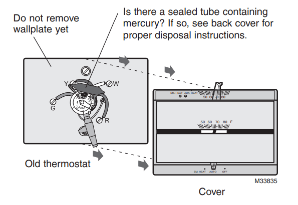
Remove old thermostat but leave wallplate with wires attached.
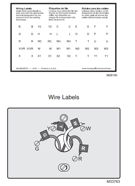
Label Wires with Tags
Label the wires using the supplied wire labels as you disconnect them.
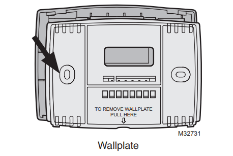
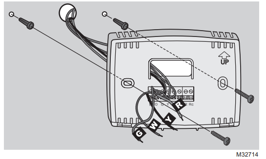
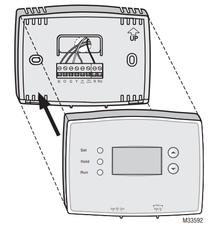
Separate Wallplate from New Thermostat
Remove wallplate from the new thermostat and mount onto wall.
Mount Wallplate
Mount the new wallplate using the included screws and anchors.
Drill 3/16-in. holes for drywall
Drill 3/32-in. holes for plaster
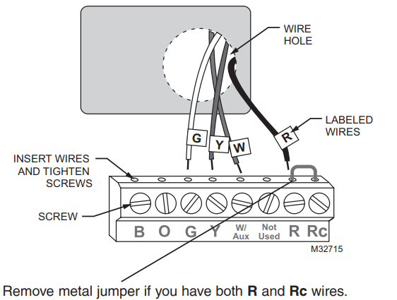
Connect Wires
Simply match wire labels.
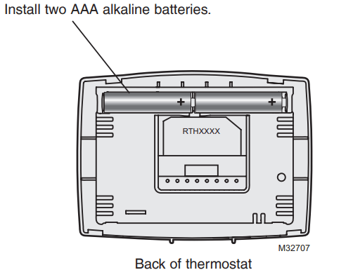
Install Batteries
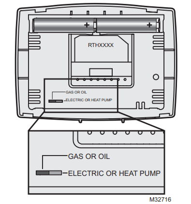
Set fan operation switch
Move the switch to the proper setting:
Gas or Oil: For gas or oil heating systems, leave the fan operation switch in this factory-set position (for systems that control the fan in a call for heat).
Electric or Heat Pump: Change the switch to this setting for heat pump or electric heat systems. (This setting is for systems that allow the thermostat to control the fan in a call for heat, if a fan wire is connected to the G terminal.)
Install Thermostat onto Wallplate
Install thermostat onto the wallplate on the wall.
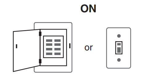
Turn Power Back On
Turn the power back on to the heating/cooling system.
If your system type is...
If your system type is:
Single Stage Heat and Cool
Heat Only or Cool Only
Congratulations, you’re done!
If your system type is:
Heat Pump* with Backup Heat
Continue with advanced installation on next page to match your thermostat to your system type.
*Heat Pump—an air conditioner that provides cooling in the summer, and also runs in reverse in the winter to provide heating
If you are not sure of your system type or if you have other questions, call us toll-free at 1-800-468-1502.
This thermostat works on 24 volt or 750 mV systems. It will NOT work on multi-stage conventional systems or 120/240 Volt systems.
SETUP
System setup
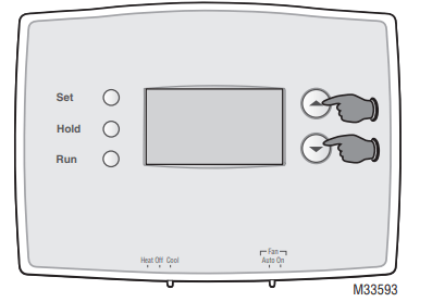
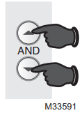
Enter System Setup
To enter system setup, press and hold both the and buttons until the display changes (approximately 5 seconds).
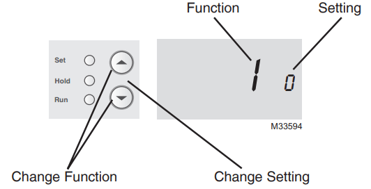
Changing Settings
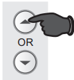
Press the or button to change the setting.
Press the and buttons simultaneously for one second to advance to the next function.
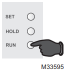
Press the Run button to exit and save settings.
NOTE: If you do not press any button for 60 seconds while you are in the setup menu, the thermostat automatically saves any changes made and exits the menu.
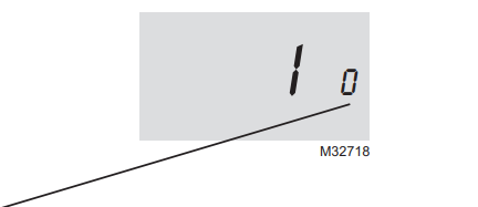
Function 1: System Type
0 Heating & cooling: Gas, oil or electric heating with central air conditioning or heat pump without auxiliary/ back-up heat.
1 Heat pump with auxiliary/backup heat: Outside compressor provides both heating and cooling.
Press the or button to select the type of Heat/Cool system you have in your home.
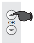
Press to change setting.
When finished, press and to advance to the next function.
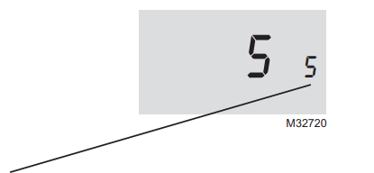
Function 5: Heating cycle rate
5 Gas or oil furnace: Use this setting if you have a standard gas or oil furnace that is less than 90% efficient.
6 Electric furnace: Use this setting if you have any type of electric heating system.
3 Hot water or high-efficiency furnace: Use this setting if you have a hot water system or a gas furnace of greater than 90% efficiency.
2 Gas/oil steam or gravity system: Use this setting if you have a steam or gravity heat system.
Press the or button to select your heating system and optimize its operation.
Press to change setting.
When finished, press and to advance to the next function.
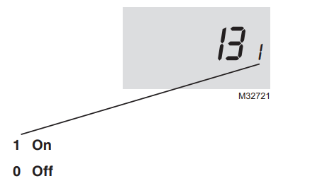
Function 13: Early Start
Early start allows the heating or cooling to turn on before the program start time, so the temperature is reached at the time you set. Simply program the desired times and temperature into the schedule. The thermostat will turn the heating or cooling on early so that the desired temperature is reached at the desired time.
Press the or button to select Early Start.
Press to change setting.
When finished, press and to advance to the next function.
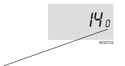
Function 14: Temperature display
0 Fahrenheit temperature display (°F)
1 Celsius temperature display (°C)
Press the or button to select Fahrenheit or Celsius temperature display
Press to change setting.
When finished, press and to advance to the next function.
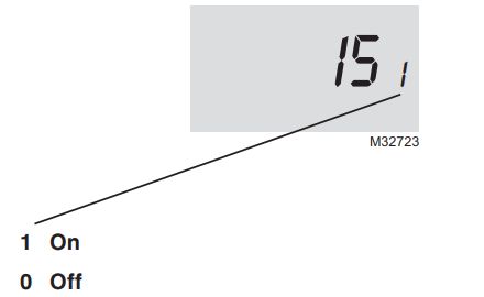
Function 15: Compressor Protection
Compressor Protection: This feature forces the compressor to wait approximately 5 minutes before restarting, to prevent equipment damage. During the wait time, the message “Cool On” or “Heat On” is displayed on screen.
Press the or button to select Compressor Protection settings.
Press to change setting.
When finished, press and to advance to the next function.
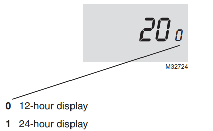
Function 20: Clock Display
Press the or button to select clock display.
Press to change setting.
When finished, press and to advance to the next function.
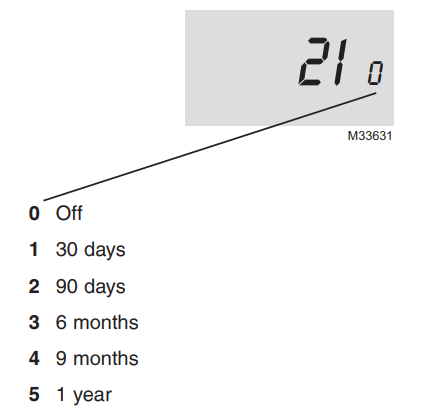
Function 21: Change Filter Timer
Press the or button to select Change Filter Timer.
Press to change setting.
When finished, press and to advance to the next function.
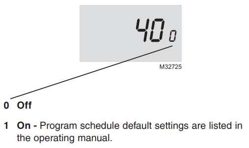
Function 40: Restore Program Schedule to Default
Press the or button to select restore program schedule to default settings.
Press to change setting
When finished, press Run to exit and save changes.
WIRING
Wiring-Conventional System
If labels do not match letters on the thermostat, check the chart below and connect to terminal as shown here (see notes, below).
If wires will be connected to both R and Rc terminals, remove metal jumper (see page 6).
Do not use C or X. Wrap bare end of wire with electrical tape.
If you have a heat pump without auxiliary/backup heat connect O or B, not both. If you do not have a heat pump, do not connect B. Wrap bare end of wire with electrical tape.
Place a jumper (piece of wire) between Y and W/Aux if you are using a heat pump without auxiliary/backup heat.
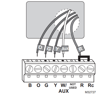
Wiring-Heat Pump
Connect wires: Heat Pump
Match each labeled wire with same letter on new thermostat.
Use a screwdriver to loosen screws, insert wires into hole under screw, then tighten screws until wire is secure.
Push any excess wire back into the wall opening.
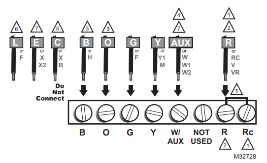
Alternate wiring (for heat pumps with auxiliary or backup heat only)
If labels do not match letters on the thermostat, check the chart below and connect to terminal as shown here (see notes, below).
Leave metal jumper in place, connecting R & Rc terminals.
If your old thermostat had both V and VR wires, stop now and contact a qualified contractor for help.
If your old thermostat had separate O and B wires, wrap the B wire in electrical tape and do not connect.
If your old thermostat had Y1, W1 and W2 wires, stop now and contact a qualified contractor for help.
Do not use C or X wire. Do not use B wire if you already have O wire. Wrap bare end of wire with electrical tape.
Do not use L wire. Wrap bare end of wire with electrical tape.
If your old thermostat had E and Aux wires (or alternate wires), connect both wires to Aux terminal.
TROUBLESHOOTING
If you have difficulty with your thermostat, please try the following suggestions. Most problems can be corrected quickly and easily
Display is blank
Make sure furnace door is closed securely.
Make sure fresh AAA alkaline batteries are correctly installed (see page 7).
Heating or cooling system does not respond
Set System switch to Heat. Make sure the temperature is set higher than the Inside temperature.
Set System switch to Cool. Make sure the temperature is set lower than the Inside temperature.
Check circuit breaker and reset if necessary.
Make sure heating & cooling power switches are on.
Make sure furnace door is securely closed.
Wait 5 minutes for the system to respond.
Temperature settings do not change
Make sure heating and cooling temperatures are set to acceptable ranges:
Heat: 40° to 90°F (4.5° to 32°C).
Cool: 50° to 99°F (10° to 37°C).
“Cool On” or “Heat On” is flashing
Compressor protection feature is engaged. Wait 5 minutes for the system to restart safely, without damage to the compressor.
“Heat On” is not displayed
Set the System switch to Heat, and set the temperature level above the current room temperature.
“Cool On” is not displayed
Set the System switch to Cool, and set the temperature level below the current room temperature.

 and
and  buttons until the display changes (approximately 5 seconds).