Loading ...
Loading ...
Loading ...
Basic Operation
-45
Switching the Input
Mode
Select the appropriate input mode for the con-
nected equipment.
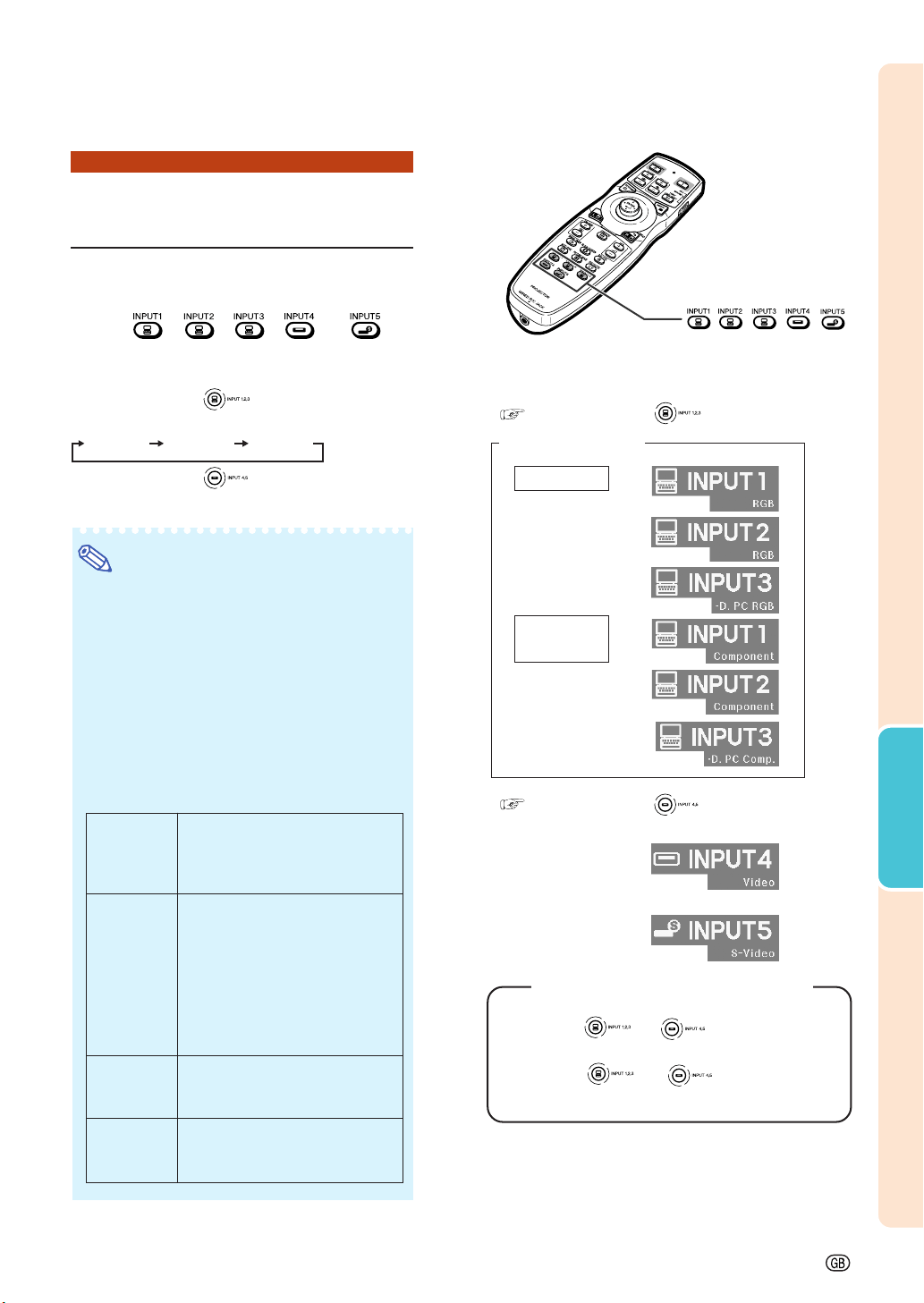
Press , , , or on
the remote control to select the input
mode.
••
••
• When pressing on the projector, the
input mode switches in order of :
INPUT 1 INPUT 2 INPUT 3
••
••
• When pressing on the projector, the
input mode switches between “INPUT 4” and
“INPUT 5”.
Note
• When no signal is received, “NO SIGNAL”
will be displayed. When non-supported sig-
nal is received, “NOT REG.” is displayed.
• When “Auto Search” of the “Options (1)”
menu is set to “ON”, the input mode with
signal can automatically be detected and
displayed. (See page 78.)
• The input mode is not displayed when “OSD
Display” of the “Options (1)” menu is set to
“Level A” or “Level B”. (See page 75.)
About the Input mode
"On-screen Display of Input Mode (Example)
Using RGB
Using
component
INPUT 1/2/3 mode
INPUT 5 mode
Using S-video
INPUT 4 mode
Using video
Used for projecting images from
equipment that sends RGB signals
or component signals connected to
the INPUT 1 or 2 terminals.
Used for projecting images
from equipment connected to
the INPUT 3 terminal.
Used for projecting images
from equipment connected to
the INPUT 4 terminal.
Used for projecting images
from equipment connected to
the INPUT 5 terminal.
INPUT 1/
INPUT 2
(RGB/
component)
INPUT 3
(digital PC
RGB/digital
PC compo-
nent/digital
video RGB/
digital video
component)
INPUT 4
(video)
INPUT 5
(S-video)
INPUT buttons
/ ///
When pressing .
When pressing .
When “Auto Search” is set to “ON”
• Pressing
or once displays the
current input mode.
• Pressing
or again starts the
automatic input search.
* The “INPUT 3”
display is an
example. (When
“Signal Type” is set
to “D. PC RGB”)
* The “INPUT 3”
display is an
example. (When
“Signal Type” is set
to “D. PC Comp.”)
Loading ...
Loading ...
Loading ...