Loading ...
Loading ...
Loading ...
7
www.napoleongrills.com
N415-0272-AU JAN 24.18
Leak Tesng Instrucons
WARNING! A leak test must be performed annually and each me a cylinder is hooked up or if a
part of the gas system is replaced.
WARNING! Never use an open ame to check for gas leaks. Be certain no sparks or open ames
are in the area while you check for leaks. Sparks or open ames will result in a re or explosion,
damage to property, serious bodily injury, or death.
Leak tesng: This must be done before inial use, annually, and whenever any gas components are
replaced or serviced. Do not smoke while performing this test, and remove all sources of ignion. See Leak
Tesng Diagram for areas to check. Turn all burner controls to the o posion. Turn gas supply valve on.
Brush a half-and-half soluon of liquid soap and water onto all joints and connecons of the regulator,
hose, manifolds and valves.
Bubbles will indicate a gas leak. Either ghten the loose joint or have the part replaced with one
recommended by the Napoleon Customer Soluons department and have the grill inspected by a cered
gas installer.
If the leak cannot be stopped, immediately shut o the gas supply, disconnect it, and have the grill
inspected by a cered gas installer or dealer. Do not use the grill unl the leak has been corrected.
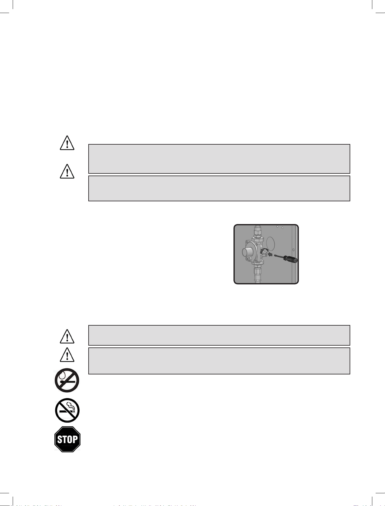
This unit includes an internal regulator which stabilizes
the gas pressure and improves grill performance. This
regulator cannot be adjusted. There is a pressure tap
located on the side of the regulator. It can be used by
a qualied service person when servicing the grill to
determine if the regulator is funconing properly. The
screw within the pressure tap must always be kept ght,
except when performing a pressure test on the regulator
(qualied service personnel only).
BUILT IN NATURAL GAS HOOK-UP: The piping up to the gas grill is the responsibility of the installer and
piping should be located as shown in the built-in instrucons. A exible metal connector is included to
simplify the installaon of the unit. Connect this exible metal connector to the are ng (3/8” SAE 45
O
Flare Connecon 5/8-18 UNF thread)
Connect the other end of the connector to the supplied gas regulator. Ensure that the exible metal
connector is protected from damage if it needs to pass through any parons. The installaon must be
performed by a licensed gas er in accordance with AS/NZS 5601, and all connecons must be leak
tested before operang the grill.
Do not use a hose to connect the unit. The supplied regulator with 3/8” SAE 45
O
Flare Inlet Connecon
(5/8-18 UNF thread) must be connected with rigid pipe, copper tube or an approved exible metal
connector which complies with with AS/NZS 5601. The gas supply pipe must be suciently sized to supply
the kPA specied on the rang plate, based on the length of the piping run. If installing a side burner,
a separate line must be branched o to the side burner unit and enter the side burner opening at the
specied locaon.
WARNING! Built in units are supplied with a drip pan which holds only a minimal amount of
grease. To prevent grease res, the pan must be cleaned aer each use.
WARNING! Access must be provided to the inside of the enclosure to make gas connecons.
DANGER! Read all instrucons carefully before operang the grill. Failure to follow these
instrucons exactly could result in a re causing serious injury or death. The enre installaon must be
leak tested before operang the grill.
Note: The gas grill is designed to operate at an inlet pressure of 1.00 kPA and must be checked aer
installaon by turning all burners on and measuring at the regulator outlet test point provided.
Loading ...
Loading ...
Loading ...