Loading ...
Loading ...
Loading ...
English
22
R
L
R
L
YP
B
P
R
Y
P
B
P
R
VIDEO
(
CVBS
)
COMPONENT
VIDEO
EXT 2
S-VIDEO
(
Y/C
)
VIDEO
(
CVBS
)
S-VIDEO
(
Y/C
)
AUDIO
COAXIAL
R
L
R
L
(DIGITAL AUDIO)
INPUT
EXT 1
EXT 3
COMPONENT VIDEO
AUDIO AUDIO
ANTENNA-IN
TV-OUT
AUD IO
OUT
S-VID EO
IN
VIDEO IN
TV
RF
S-VIDEO
OUT
IN
AUDIO
R L
VIDEO
CABLE
SATELLITE
ANTENNA
VIDEO
IN
OUT
IN
AUDIO
L
AUDIO
R
VIDEO
OUT
AUDIO
L
AUDIO
R
VHF/UHF
RF IN
VHF/UHF
RF OUT
S-VIDEO
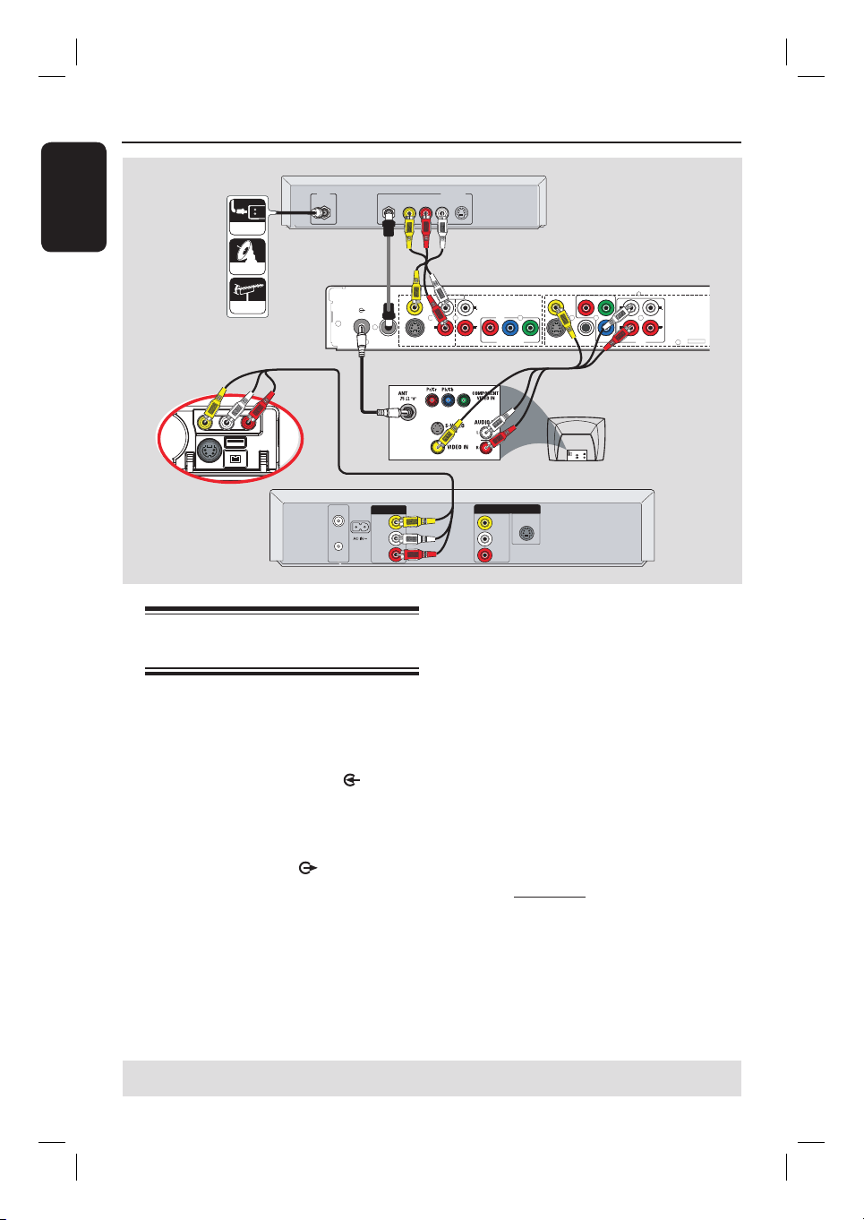
Step 2: Optional Connections (continued)
Connecting to a VCR and
Cable Box/Satellite Receiver
A
Connect the Antenna/Cable TV signal to
the antenna input (RF IN) jack on the
Cable Box/ Satellite Receiver.
B
Use the supplied RF coaxial cable to
connect the ANTENNA-IN
jack on
the recorder to the RF OUT jack on the
Cable Box/ Satellite Receiver.
C
Use a RF coaxial cable (not supplied) to
connect the TV-OUT jack on the
recorder to the antenna input jack on
your TV (VHF/UHF RF IN.)
D
Use the supplied audio/ video cables to
connect the VIDEO(CVBS) /AUDIO-
INPUT (red/white/yellow) jacks on the
recorder to the matching VIDEO/AUDIO
output jacks on the Cable Box/ Satellite
Receiver.
E
Use the audio/video cables to connect
the VIDEO(CVBS)/AUDIO -
OUTPUT (red/whote/yellow) jacks on
the recorder to the matching VIDEO/
AUDIO input jacks on the TV.
F
Use another set of audio/video cables to
connect the CAM1/ L-AUDIO-R jacks
on the front panel of the recorder to the
to the matching VIDEO/AUDIO output
jacks on the VCR.
TIPS: Refer to the respective connected device’s user manual for other possible connections.
C
A
D
F
Rear of a VCR
(Example only)
E
Rear of a Cable Box
or Satellite Receiver
(Example only)
B
Front Panel of
recorder
Loading ...
Loading ...
Loading ...