Loading ...
Loading ...
Loading ...
6-6
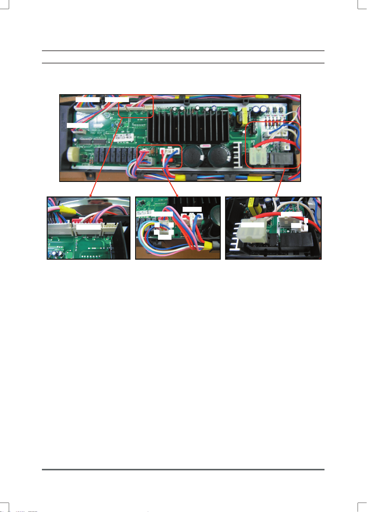
-If you plug in the power cord and turn Power S/W on, memorized data is displayed.
If any data is not displayed, check the followings.
�-
�-�-
�- CN3
CN
3CN3
CN
3 �c
吏吏
吏
欄
欄欄
欄 CN9
CN
9CN9
CN
9 卵
卵卵
卵
CNw0
CN
w0CNw0
CN
w0
卵
卵卵
卵 CN8
CN8CN8
CN8 柩
柩柩
柩
欄
欄欄
欄 CN5
CN
5CN5
CN
5 卵
卵卵
卵
CN7
CN
7CN7
CN
7
卵
卵卵
卵
濫
濫濫
濫
柝
柝柝
柝
枸
枸枸
枸
卵
卵卵
卵
嵐
嵐嵐
嵐
卵
卵卵
卵 RY9
RY
9RY9
RY
9 嵐
嵐嵐
嵐
枴
枴枴
枴 C
CC
CN4
N4N4
N4 藍
藍藍
藍
倫
倫倫
倫 CN2
CN
2CN2
CN
2 塁
塁塁
塁
倫
倫倫
倫 CNw
CN
wCNw
CNw 塁
塁塁
塁
Thermistor Check
Check Voltage at Pin #6 and #3 of CN3
Tester Check = DC2.5V
If it reads 5V, check if its connector is engaged properly.
Door Switch Check
Check Voltage at Pin #6 and #4 of CN3
When Door Open = DC5V
When Door Close = DC0V
Water Sensor Check
Check Voltage and Frequency at Pin #6 and #7 of CN3
Reset water level = DC2.5V, 25.8KHz
Check Voltage and Frequency at Pin #6 and #8 of CN3
Reset water level = DC2.5V, 25.8KHz
Sump Sensor Check
Check Voltage at Pin #4 and #2 of CN8
Tester Check = DC0V or 3.75V
Check Voltage at Pin #4 and #3 of CN8
Tester Check = DC0V or 3.75V
Motor Check
Resistance at Pin #1 and #2 of CN9 =11.6Ω
Resistance at Pin #1 and #3 of CN9 =11.6Ω
Resistance at Pin #2 and #3 of CN9 =11.6Ω
Door Lock Check
Check Voltage at Pin #1 of CN5 and Pin #7 of CN10
When Door Lock = AC120V
Check Voltage at Pin #1 of CN5 and Pin #2 of CN7
When Door Lock = AC120V
Door Unlock Check
Check Voltage at Pin #1 of CN5 and Pin #8 of CN10
When Door Unlock = AC120V
Drain Motor Check
Check Voltage at Pin #1 of CN5 and Pin #6 of CN10
When Drain Pump operates = AC120V
Water Valve Check
Check Voltage at Pin #1 of CN5 and Pin #1,2,3,4 of CN10
When each Valve operates = AC120V
AC Power Check
Check Voltage at Pin #1 and #3 of CN5
Check Voltage at Pin #1 of CN5 and Pin #1 of CN6
Tester Check = AC120V
Heater Relay Check
Check Voltage at Pin #1 of CN5 and Pin #2 of RY9
When Heater Relay operates = AC120V
Loading ...
Loading ...
Loading ...