Loading ...
Loading ...
Loading ...
6-16
6-16
Electrical servicing
Speed sensor
System check
NOTICE
Before starting this inspection, check the inspection of
the speedometer system.
Checking the air gap
Safely support the motorcycle with a lifting device or
equivalent and raise the wheel off the ground.
Measure the gap (air gap) between the sensor and the
pulse generator ring at different points by turning the
wheel slowly.
It must be within the specification.
Standard: 0.5 – 1.5 mm (0.031 – 0.035 in)
The air gap cannot be adjusted.
If it is not within the specification, check whether there
are deformities, damage or if any of the parts assembled
are loose.
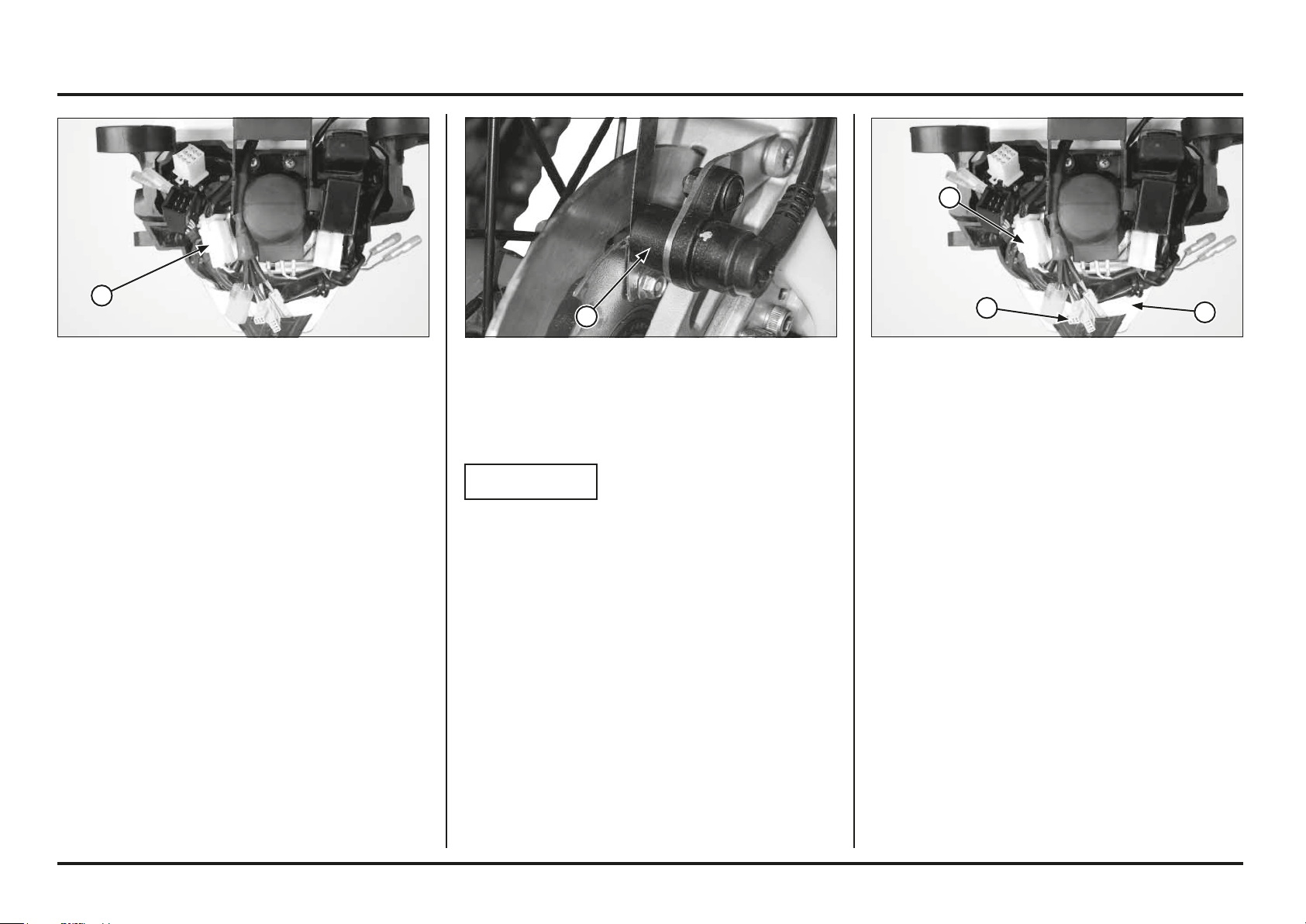
(1) SPEED SENSOR(1) CONNECTOR 6P
Power input line
Measure the voltage between the connector 6P of the
speedometer and the ground.
Connection: White/Red(+) and Ground (–)
With the engine on, around 12V should be received.
If there is no voltage, check the existence of an open
circuit in the White/Red wire.
Ground line
Measure the continuity between the connector 6P of the
speedometer and the ground.
Connection: Green and Ground
There must be continuity at all times.
If there is no continuity, check the existence of an open
circuit in the green wire.
(1) HOUSING FOR THE UPPER HEADLIGHT
(2) CONNECTOR 6P
(3) CONNECTOR 3P
Checking the speed sensor
Remove the housing for the upper headlight.
Check if there are loose or defective contacts in the
connector 3P (white) of the speed sensor.
Connect the connector 3P (white) of the speed sensor.
Start the engine.
Measure the voltage between the terminals of the
connector 3P (white) of the speed sensor on the wire
side.
Connection: Red (+) and Black (–)
Standard: 5V.
If the standard voltage appears, replace the speed sensor.
If there is no standard voltage, check the following:
The blue wire in case there is an open circuit.
The red wire in case there is an open circuit.
Speedometer.
1
1
3
2
1
Loading ...
Loading ...
Loading ...