Loading ...
Loading ...
Loading ...
8
Connecting the Gas
WARNING
• Close the gas-supply valve and unplug the range before you
connect the gas line.
• Do not overtighten the gas connections/fittings.
• Do not use Teflon tape or plumber’s putty on flex line
connections.
• (LP installations) The LP gas tank must have its own high-
pressure regulator (in addition to the pressure regulator
provided with the range).
• The maximum gas-supply pressure to the regulator must
never exceed 1/2 psi (pound/square inch) or 3.5 kPa.
• The range and shut-off valve must be disconnected from the
gas-supply piping during pressure tests over 1/2 psi (3.5 kPa).
• The gas shut-off valve must be closed during pressure tests
at or below 1/2 psi (3.5 kPa).
• Check all gas lines for leaks as instructed to avoid a fire or
explosion hazard. Do not use a flame to check for leaks.
NOTE: The gas pressure regulator is pre-set at the factory for the
type of gas intended for use with the range.
To verify that the range is compatible with the supplied gas, check
the rating label (see inside front cover). LP-gas ranges have LP
in the model number. Call your dealer if the range is incompatible
with the gas supply.
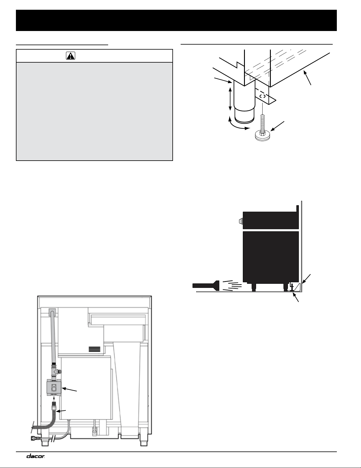
1. Close the gas-supply valve, and unplug the range.
2. Connect a flexible gas-supply line to the gas shut-off valve.
The line must be long enough so the range can be pulled out
for service without disconnecting the line.
3. Slide the gas line through the range’s access holes in the
back of chassis and up to the regulator. (Move the wires
inside the access holes so they do not catch on the gas line.)
4. Connect the gas line to the regulator.
5. Turn off all burner knobs, and open the gas-supply valve.
6. With a soap-and-water solution, check all lines and
connections for leaks.
7. Having verified there are no leaks, close the gas-supply valve
to the range.
Installation Instructions
Regulator
Flexible
Gas Line
Finalizing the Anti-Tip Installation
1. Peel the protective plastic from the range, including the door.
2. Adjust the leveling legs, as needed, so the trim around the
cooktop is flush with or above the countertop.
3. Locate the anti-tip foot on the back of the range. Lower (turn)
the foot until it is 1/16” (2 mm) from the floor.
4. Carefully slide the range into position. (With a flashlight, verify
that the anti-tip foot engages the anti-tip bracket.)
5. Use a level to confirm that the range is parallel to the ground
and stable. Re-adjust the legs and change the height if
necessary. Make sure the range does not tip or lean.
Anti-tip
bracket
Anti-tip foot
up
down
Back of range
Anti-Tip Foot
(location varies)
1 1/4” *
* Distance to floor:
4 1/16” to 5 5/16”
Rear leg
Loading ...
Loading ...
Loading ...