Loading ...
Loading ...
Loading ...
TEC_TM_009 Rev. B
December 31, 2019 Page 25 of 50
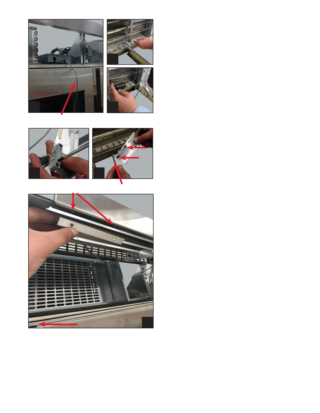
STEP 12
Route the reed switch wires through the P-clips
and bushings in the new grill.
Image 12a, 12b & 12c.
STEP 13
Reconnect door switch wires to reed switch (it
doesn’t matter which wire goes to each terminal)
and install the cover.
Image 13a & 13b.
STEP 14
Connect the reed switch to the new grill using
the pre drilled holes and pop rivets. Pay close
attention to how the doors are hinged, for this will
determine where to install the door switch bracket
into the louver grill. Each door has a magnet on the
handle side of the door. The reed switch bracket
will install in close proximity to this magnet.
Image 14.
STEP 15
Install the units into place by walking them into
the opening. Make final leveling adjustments if
needed. Close the louver grill, plug each unit in
and turn the power on by holding the power button
for 3 seconds.
STEP 16
Three minutes after plugging in the units, open
and close each door individually, making sure
the evaporator fans and lights are shutting off
when the door is opened and closed. Note: all
units have the ability to leave the lights on all the
time, bypassing the door switch. However, the
evaporator (interior) fans should always turn on
and off with door openings. You should also hear a
low-pitched click from the control board area when
the door is opened and shut.
12a
14
NOTE: P-CLIPS WILL ONLY BE USED ON EACH
END OF THE NEW GRILL NOT IN THE CENTER
(APPLIES TO 90 INCH ONLY).
12c
12b
Reed Switch Wire
13a 13b
Plastic Cover
Pre-drilled Holes in Louver Grill
Magnet
Loading ...
Loading ...
Loading ...