TRUE RESIDENTIAL
®
TR-30 / TR-36
INSTALLATION / USER GUIDE
PRESERVE THE MOMENT
®
TEC_TM_009 Rev. B December 27, 2019
212530
Page i of 50

THANK YOU
FOR YOUR PURCHASE
December 27, 2019Page ii of 50 TEC_TM_009 Rev. B

TEC_TM_009 Rev. B
December 31, 2019 Page 1 of 50
O W N E R S H I P, SAFETY PRECAUTIONS, DISPOSAL OF OLD REFRIGERATOR, CFC DISPOSAL
3-4
SITE PREPARATION, ELECTRICAL REQUIREMENTS, ANTI-SWEAT FOAM END PANELS
5-8
PLAN VIEWS
9-16
ANTI-TIP BRACKET INSTALLATION, LEVELING THE UNIT, JOINING KIT INSTALLATION
17-26
REFRIGERATOR AND FREEZER BASIC ELECTRONIC CONTROL OPERATIONS, SHOWROOM MODE
37-34
DUAL ZONE BASIC ELECTRONIC CONTROL OPERATIONS, SHOWROOM MODE
35-42
SHELVING, REFRIGERATOR STORAGE, FREEZER STORAGE, REMOVING THE DOORS,
KICK PLATE INSTALLATION
43-46
STAINLESS STEEL EQUIPMENT CARE & CLEANING, GENERAL MAINTENANCE, CONDENSATION,
DATA TAG, WARRANTY STATEMENT, CONTACT US
47-50
NOTE:
AS WE STRIVE FOR CONTINUOUS IMPROVEMENTS, FEATURES AND SPECIFICATIONS ARE SUBJECT TO CHANGE WITHOUT NOTICE.
IND E X

TRUE RESIDENTIAL
®
TEC_TM_009 Rev. B
December 31, 2019 Page 2 of 50
Commercial refrigeration refined for the home, envied in the industry,
and crafted—gorgeously—in America.
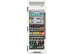
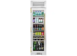
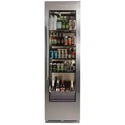
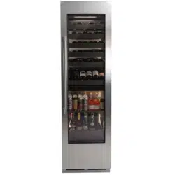
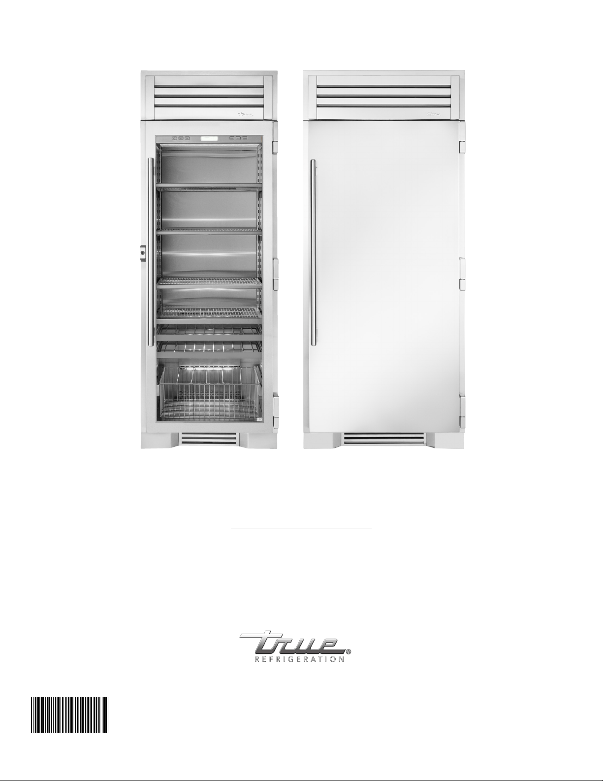
30 & 36 INCH REFRIGERATOR, FREEZER & DUAL ZONE COLUMN
STAINLESS SOLID DOOR
30” FREEZER
COLUMN
30” REFRIGERATOR
COLUMN
STAINLESS SOLID DOOR
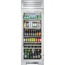
STAINLESS GLASS DOOR
30” DUAL ZONE
WINE COLUMN
STAINLESS GLASS DOOR
30” REFRIGERATOR
COLUMN
STAINLESS GLASS DOOR
36” REFRIGERATOR
COLUMN
36” REFRIGERATOR
COLUMN
STAINLESS SOLID DOOR
36” FREEZER
COLUMN
STAINLESS SOLID DOOR
STAINLESS GLASS DOOR
30” REFRIGERATOR
BEVERAGE COLUMN

TEC_TM_009 Rev. B
December 31, 2019 Page 3 of 50
O w n e r s h i p
s a f e t y p r e c a u t i O n s
D i s p O s a l O f t h e O l D r e f r i g e r a t O r
c f c D i s p O s a l
3 - 4
PRESERVE THE MOMENT
®

TRUE RESIDENTIAL
®
TEC_TM_009 Rev. B
December 31, 2019 Page 4 of 50
• Do not store or use gasoline or other flammable
vapors and liquids in the vicinity of this or any
other appliance.
• Keep hands away from the “pinch point” areas
(gaps between the doors and between the doors
and cabinet). Small areas are not necessarily safe.
• Unplug the refrigerator before cleaning and
making repairs.
• Setting temperature control to OFF only removes
power from the refrigeration system, it does not
remove power from other circuits. For example,
temperature control and lights.
NOTE: WE STRONGLY RECOMMEND THAT ANY
SERVICING BE PERFORMED BY A QUALIFIED
INDIVIDUAL.
PROPER DISPOSAL OF THE OLD
REFRIGERATOR
DANGER: Risk of child entrapment. Before you throw
away your old refrigerator or
freezer:
• Take off the doors
• Leave the shelves in place
so that children may not
easily climb inside
DANGER: Risque de
piégeage de l´enfant.
Avant de jeter votre vieux
réfrigérateur ou congélateur:
• Enlevez les portes.
• Laissez les étagéres en place de sorte que les
enfants ne puissent pas facilement monter à
l´intérieur.
CFC DISPOSAL
Your old refrigerator may have a cooling system that
used CFCs (chlorofluorocarbons). CFCs are believed
to harm stratospheric ozone. If you are throwing away
your old refrigerator, make sure the CFC refrigerant
is removed for proper disposal by a qualified service.
If you intentionally release this CFC refrigerant you
can be subject to fines and imprisonment under
provisions of the environment legislation.
OWNERSHIP
THIS APPLIANCE IS NOT INTENDED FOR USE BY
PERSONS (INCLUDING CHILDREN) WITH REDUCED
PHYSICAL, SENSORY OR MENTAL CAPABILITIES,
OR LACK OF EXPERIENCE AND KNOWLEDGE,
UNLESS THEY HAVE BEEN GIVEN SUPERVISION OR
INSTRUCTION CONCERNING USE OF THE APPLIANCE
BY A PERSON RESPONSIBLE FOR THEIR SAFETY.
TO INSURE THAT YOUR UNIT WORKS PROPERLY
FROM THE FIRST DAY, IT MUST BE INSTALLED
PROPERLY.
NOTE: WE HIGHLY RECOMMEND A TRAINED
REFRIGERATION MECHANIC AND ELECTRICIAN
INSTALL YOUR TRUE RESIDENTIAL
®
CA BINE T.
THE COST OF A PROFESSIONAL INSTALLATION IS
MONEY WELL SPENT.
Before you start to install your True Residential
®
Cabinet, carefully inspect it for freight damage. If
damage is discovered, immediately file a claim with
the delivery freight carrier. True is not responsible
for damage incurred during shipment. This appliance
is intended to be used in household and similar
applications such as:
• Staff kitchen areas in shops, offices and other
working environments;
• Bed and breakfast type environments;
• Catering and similar non-retail applications.
Any questions about the installation please
contact your True dealer or True Technical Service
Department at 844-746-9423. Please have your
model and serial numbers available when you call our
Service Department.
SAFETY PRECAUTIONS
• This refrigerator must be properly installed
and located in accordance with the installation
instructions before it is used.
• Do not allow children to climb, stand or hang on
the shelves in the refrigerator. They could seriously
injure themselves or damage the refrigerator.

TEC_TM_009 Rev. B
December 31, 2019 Page 5 of 50
s i t e p r e p a r a t i O n
e l e c t r i c a l r e q u i r e m e n t s
a n t i - s w e a t f O a m e n D p a n e l s
5 - 8
PRESERVE THE MOMENT
®
TRUE RESIDENTIAL
®
TEC_TM_009 Rev. B
December 31, 2019 Page 6 of 50
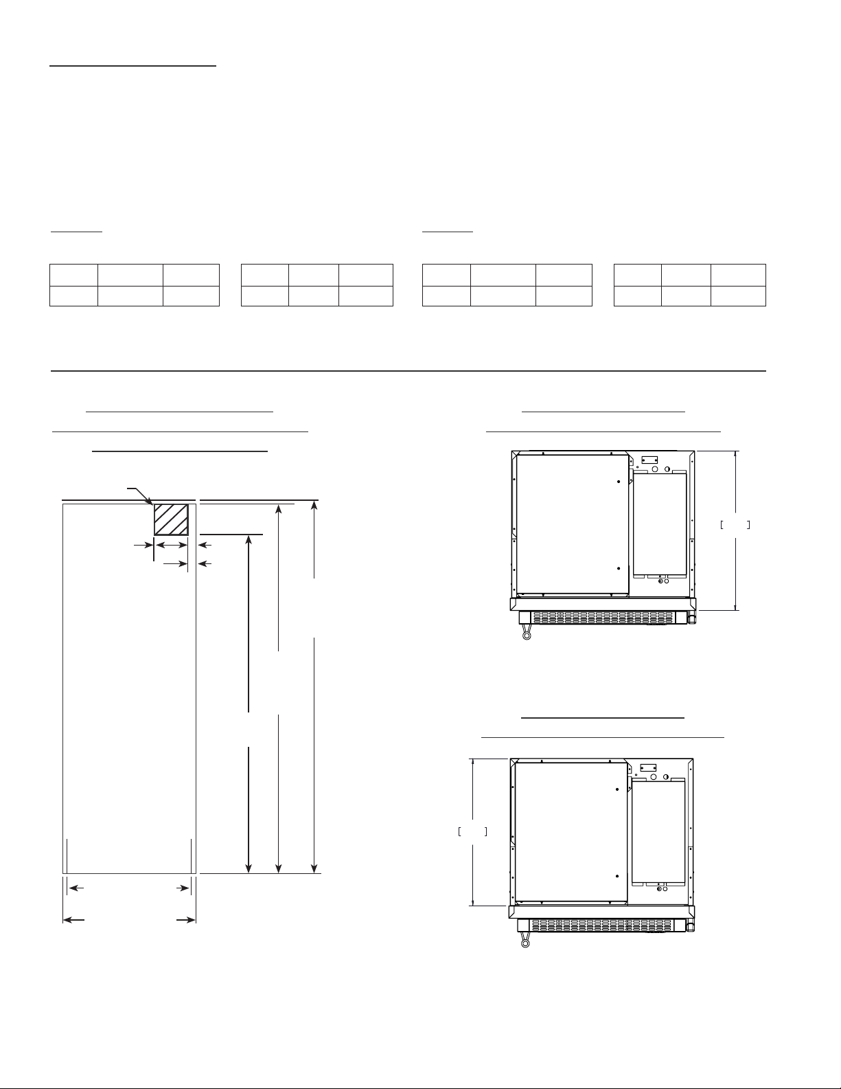
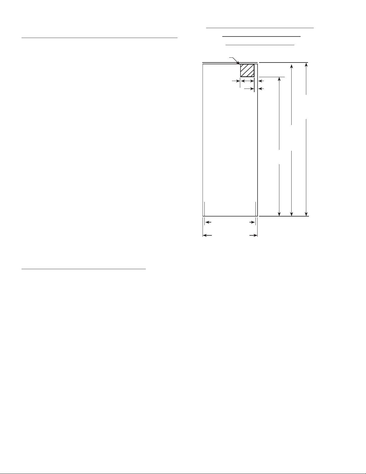
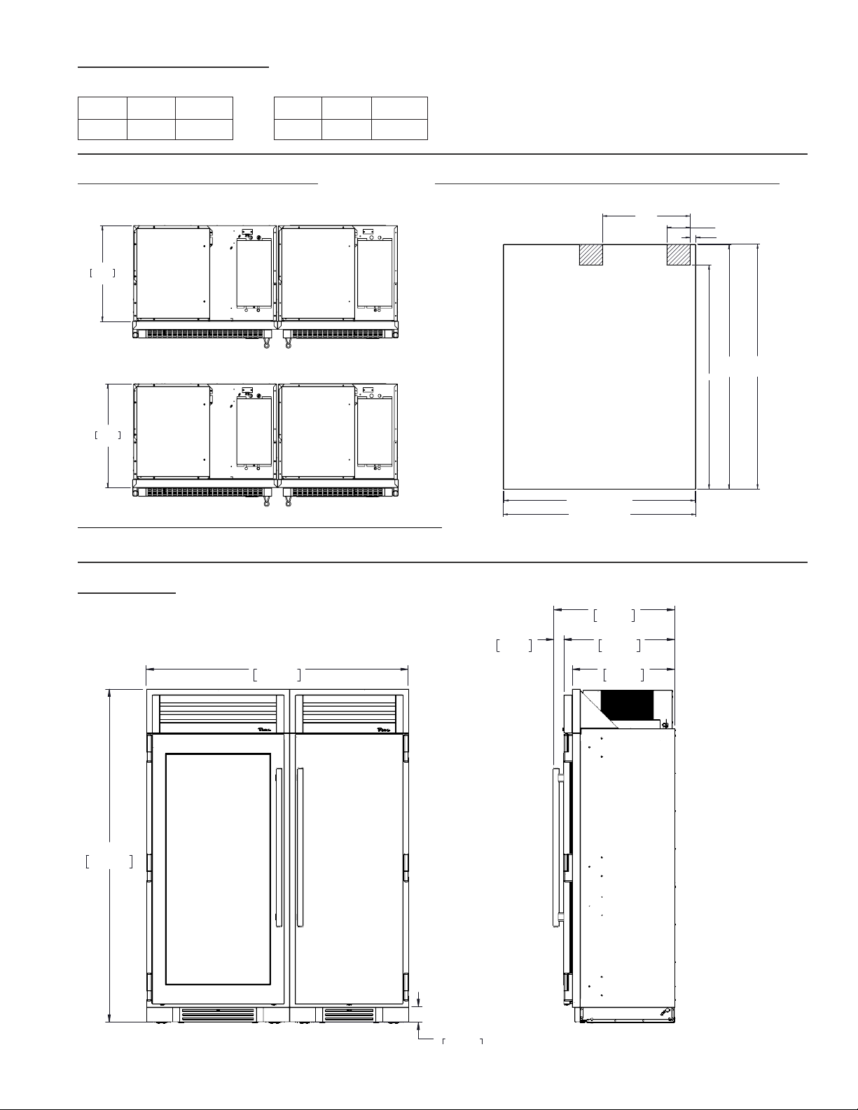
SITE PREPARATION
• Rough Opening dimensions. (See figure 1)
• For FLUSH installations the front face of the unit will be flush with the surrounding cabinets. (See figure 2)
• For PROUD (Standard) installations, the front face of the unit will extend beyond cabinets. (See figure 3)
TR-30 – TOP VIEW
FIGURE 3 - PROUD INSTALL
23 25/32"
604mm
PROUD INSTALL
25 25/32"
655mm
FLUSH INSTALL
TR-30REF-R-SG-A
R
TR-30 – TOP VIEW
FIGURE 2 - FLUSH INSTALL
23 25/32"
604mm
PROUD INSTALL
25 25/32"
655mm
FLUSH INSTALL
TR-30REF-R-SG-A
R
TR-30 TR-36
FLUSH OPENING DIMENSIONS PROUD OPENING DIMENSIONS
Width Depth Height
29 ¾" 23 ⁄" 84"
Width Depth Height
30 ¼" 25 ⁄" 84 ¼"
FLUSH OPENING DIMENSIONS PROUD OPENING DIMENSIONS
Width Depth Height
35 ¾" 23 ⁄" 84"
Width Depth Height
36 ¼" 25 ⁄" 84 ¼"
NOTE: DIMENSIONS MAY VARY BY ±
1
/
8
”
* BECAUSE OF THE WEIGHT OF THIS UNIT, IT IS RECOMMENDED TO CONSULT A FLOORING EXPERT PRIOR TO INSTALLATION. THE
FLOORING BENEATH THE UNIT SHOULD BE RATED TO SUPPORT AT LEAST 150 POUNDS PER SQUARE FOOT.
NOTE: IT IS NOT RECOMMENDED TO INSTALL UNITS SIDE BY SIDE WITH HINGES TOUCHING EACH
OTHER. IF YOU PLAN TO INSTALL UNITS HINGE TO HINGE, CALL TECH SUPPORT AT 844-746-9423 FOR
INSTALLATION INSTRUCTIONS.
TR-30 – FRONT VIEW
FIGURE 1 - ROUGH OPENING
& ELECTRICAL AREA
84"
(2134 mm)
PROUD
INSTALL
84
1
/
4
"
(2140 mm)
FLUSH
INSTALL
77"
(1956 mm)
2"
(51 mm)
8"
(204 mm)
Electrical located
in this area.
30
1
/
4
"
(769 mm)
29
3
/
4
"
(756 mm)
FLUSH
INSTALL
PROUD
INSTALL
TEC_TM_009 Rev. B
December 31, 2019 Page 7 of 50
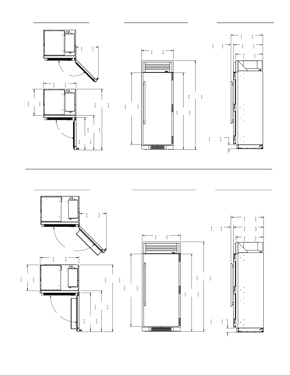
TR-30 – TOP VIEW TR-30 – FRONT VIEW
TR-36 – TOP VIEW TR-36 – FRONT VIEW
83 15/16"
2132mm
30"
762mm
67 29/32"
1725mm
DOOR
HEIGHT
72 5/8"
1845mm
25 25/32"
655mm
27 29/32"
709mm
30 15/32"
774mm
2 9/16"
65mm
3 15/16"
100mm
90°
55 1/4"
1403mm
23 25/32"
604mm
29 15/32"
748mm
31 15/32"
799mm
29 9/16"
751mm
135°
20 11/16"
525mm
TR-30DZW-R-SG-A
R
83 15/16"
2132mm
30"
762mm
67 29/32"
1725mm
DOOR
HEIGHT
72 5/8"
1845mm
25 25/32"
655mm
27 29/32"
709mm
30 15/32"
774mm
2 9/16"
65mm
3 15/16"
100mm
90°
55 1/4"
1403mm
23 25/32"
604mm
29 15/32"
748mm
31 15/32"
799mm
29 9/16"
751mm
135°
20 11/16"
525mm
TR-30DZW-R-SG-A
R
30"
762mm
67 29/32"
1725mm
DOOR
HEIGHT
72 5/8"
1845mm
83 15/16"
2132mm
25 25/32"
655mm
27 29/32"
709mm
30 15/32"
774mm
2 9/16"
65mm
3 15/16"
100mm
135°
20 19/32"
523mm
23 25/32"
604mm
55 1/4"
1403mm
29 15/32"
748mm
31 15/32"
799mm
90°
29 9/16"
751mm
TR-30REF-R-SS-A
R
NOTE: DIMENSIONS MAY VARY BY ±
1
/
8
”
36"
915mm
83 15/16"
2132mm
72 5/8"
1845mm
67 29/32"
1725mm
DOOR
HEIGHT
3 15/16"
100mm
27 29/32"
709mm
25 25/32"
655mm
30 15/32"
774mm
2 9/16"
65mm
90°
23 25/32"
604mm
35 9/16"
903mm
61 1/4"
1556mm
37 15/32"
952mm
35 15/32"
901mm
135°
24 13/16"
631mm
TR-36REF-R-SS-A
R
36"
915mm
83 15/16"
2132mm
72 5/8"
1845mm
67 29/32"
1725mm
DOOR
HEIGHT
3 15/16"
100mm
27 29/32"
709mm
25 25/32"
655mm
30 15/32"
774mm
2 9/16"
65mm
90°
23 25/32"
604mm
35 9/16"
903mm
61 1/4"
1556mm
37 15/32"
952mm
35 15/32"
901mm
135°
24 13/16"
631mm
TR-36REF-R-SS-A
R
36"
915mm
83 15/16"
2132mm
72 5/8"
1845mm
67 29/32"
1725mm
DOOR
HEIGHT
3 15/16"
100mm
27 29/32"
709mm
25 25/32"
655mm
30 15/32"
774mm
2 9/16"
65mm
90°
23 25/32"
604mm
35 9/16"
903mm
61 1/4"
1556mm
37 15/32"
952mm
35 15/32"
901mm
135°
24 13/16"
631mm
TR-36REF-R-SS-A
R
36"
915mm
83 15/16"
2132mm
72 5/8"
1845mm
67 29/32"
1725mm
DOOR
HEIGHT
3 15/16"
100mm
27 29/32"
709mm
25 25/32"
655mm
30 15/32"
774mm
2 9/16"
65mm
90°
23 25/32"
604mm
35 9/16"
903mm
61 1/4"
1556mm
37 15/32"
952mm
35 15/32"
901mm
135°
24 13/16"
631mm
TR-36REF-R-SS-A
R
TR-30 – SIDE VIEW
30"
762mm
67 29/32"
1725mm
DOOR
HEIGHT
72 5/8"
1845mm
83 15/16"
2132mm
25 25/32"
655mm
27 29/32"
709mm
30 15/32"
774mm
2 9/16"
65mm
3 15/16"
100mm
135°
20 19/32"
523mm
23 25/32"
604mm
55 1/4"
1403mm
29 15/32"
748mm
31 15/32"
799mm
90°
29 9/16"
751mm
TR-30REF-R-SS-A
R
TR-36 – SIDE VIEW
TRUE RESIDENTIAL
®
TEC_TM_009 Rev. B
December 31, 2019 Page 8 of 50
ELECTRICAL REQUIREMENTS
TR-30/TR-36
For all built-in models, the electrical supply should be
located within the shaded area shown in the illustration.
Follow the National Electrical Code and local codes
and ordinances when installing the receptacle. A
dedicated circuit, supplying only this appliance is
required. A ground fault circuit interrupter (GFCI) is not
recommended and may cause interruption of operation.
If the supply cord is damaged, it must be replaced by
the manufacturer, its service agent or similarly qualified
person in order to avoid a hazard.
• POWER SUPPLY 115 V AC, 60 HZ
• CIRCUIT BREAKER 15 AMP
• RECEPTACLE 3-PRONG GROUNDING-TYPE
NOTES:
• THE OUTLET MUST BE CHECKED BY A
QUALIFIED ELECTRICIAN TO BE SURE THAT
IT IS WIRED WITH THE CORRECT POLARITY.
• VERIFY THAT THE OUTLET IS PROPERLY
GROUNDED.
TR-30/TR-36 – FRONT VIEW
ROUGH OPENING &
ELECTRICAL AREA
84"
(2134 mm)
PROUD
INSTALL
84
1
/
4
"
(2140 mm)
FLUSH
INSTALL
77"
(1956 mm)
2"
(51 mm)
8"
(204 mm)
Electrical located
in this area.
30
1
/
4
"
(769 mm)
29
3
/
4
"
(756 mm)
FLUSH
INSTALL
PROUD
INSTALL
ANTI-SWEAT FOAM END PANELS
When installing two units side-by-side, it is recommended to leave a
5
⁄8" gap between the cabinets, to ensure
that moisture does not develop. Anti-sweat foam end panels can be purchased from our parts department by
calling (844) 849-6226, or emailing trueresidentialparts@truemfg.com. If installing anti-sweat foam end panels,
we recommend that a panel be applied to each of the units being joined together.

TEC_TM_009 Rev. B
December 31, 2019 Page 9 of 50
9 - 16
PRESERVE THE MOMENT
®
PLAN VIEWS
t r - 3 0 / t r - 4 2
t r - 3 0 / t r - 4 8
t r - 3 0 / t r - 3 0
t r - 3 0 / t r - 3 0 / t r - 3 0
t r - 3 6 / t r - 3 6
t r - 3 6 / t r - 3 0
TRUE RESIDENTIAL
®
TEC_TM_009 Rev. B
December 31, 2019 Page 10 of 50
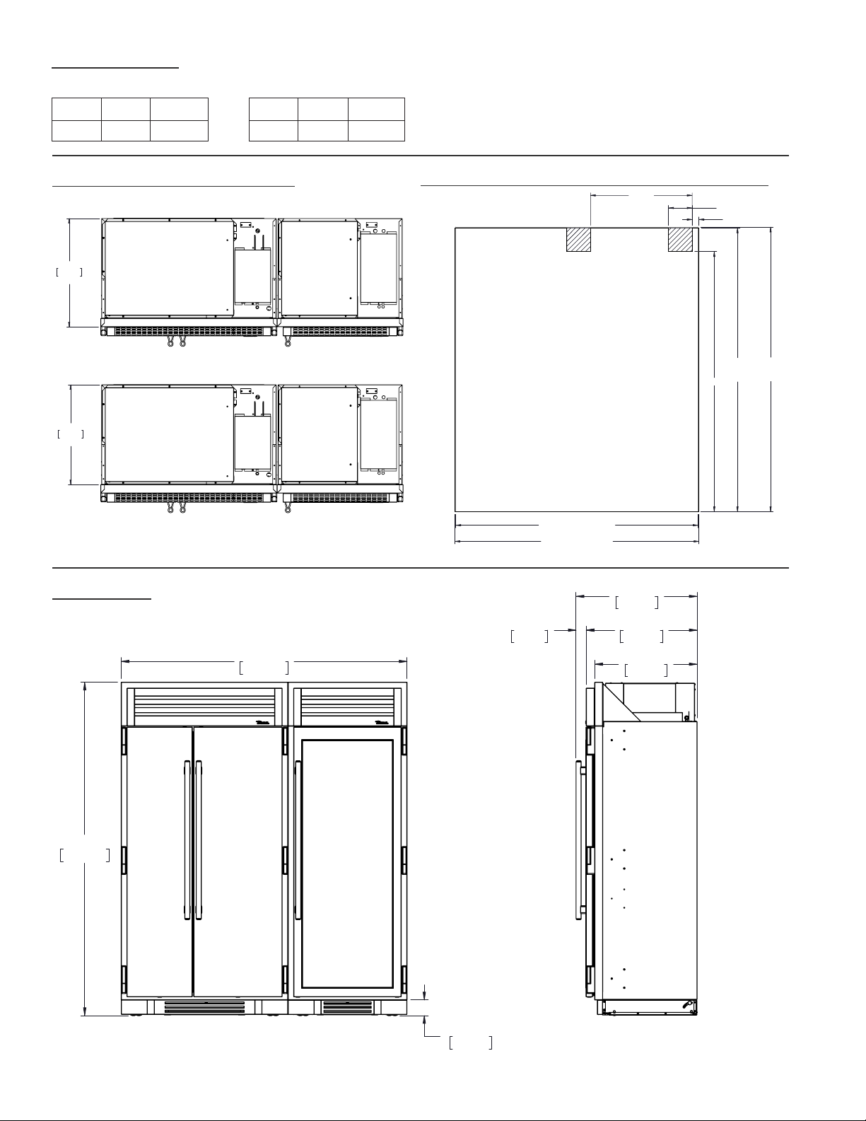
FLUSH VS. PROUD INSTALL
PLAN VIEW
TR-30 / TR-42
ROUGH OPENING & ELECTRICAL AREA
FLUSH OPENING DIMENSIONS PROUD OPENING DIMENSIONS
Width Depth Height
71¾" 23 ⁄" 84"
Width Depth Height
72¼" 25 ⁄" 84 ¼"
23 25/32"
604mm
PROUD INSTALL
25 25/32"
655mm
FLUSH INSTALL
TR-42,30DZW
R
23 25/32"
604mm
PROUD INSTALL
25 25/32"
655mm
FLUSH INSTALL
TR-42,30DZW
R
71 3/4" PROUD INSTALL
72 1/4" FLUSH INSTALL
84"
PROUD
INSTALL
84 1/4"
FLUSH
INSTALL
77"
2"
7" TYP
30 1/8"
TR-42,30DZW
R
72 1/32"
1829mm
83 15/16"
2132mm
3 15/16"
100mm
30 15/32"
774mm
2 9/16"
65mm
25 25/32"
655mm
27 29/32"
709mm
TR-42,30DZW
R
NOTE: DIMENSIONS MAY VARY BY ±
1
/
8
"

TEC_TM_009 Rev. B
December 31, 2019 Page 11 of 50
TR-30 / TR-48
FLUSH OPENING DIMENSIONS PROUD OPENING DIMENSIONS
Width Depth Height
77¾" 23 ⁄" 84"
Width Depth Height
78¼" 25 ⁄" 84 ¼"
FLUSH VS. PROUD INSTALL
PLAN VIEW
23 25/32"
604mm
PROUD INSTALL
25 25/32"
655mm
FLUSH INSTALL
TR-48,30DZW
R
23 25/32"
604mm
PROUD INSTALL
25 25/32"
655mm
FLUSH INSTALL
TR-48,30DZW
R
77 3/4" PROUD INSTALL
78 1/4" FLUSH INSTALL
84"
PROUD
INSTALL
84 1/4"
FLUSH
INSTALL
77"
2"
7" TYP
30 1/8"
TR-48,30DZW
R
83 15/16"
2132mm
78 1/32"
1982mm
3 15/16"
100mm
27 29/32"
709mm
25 25/32"
655mm
30 15/32"
774mm
2 9/16"
65mm
TR-48,30DZW
R
ROUGH OPENING & ELECTRICAL AREA
NOTE: DIMENSIONS MAY VARY BY ±
1
/
8
"
TRUE RESIDENTIAL
®
TEC_TM_009 Rev. B
December 31, 2019 Page 12 of 50
TR-30 / TR-30
FLUSH OPENING DIMENSIONS PROUD OPENING DIMENSIONS
Width Depth Height
59¾" 23 ⁄" 84"
Width Depth Height
60¼" 25 ⁄" 84 ¼"
FLUSH VS. PROUD INSTALL
PLAN VIEW
23 25/32"
604mm
PROUD INSTALL
25 25/32"
655mm
FLUSH INSTALL
TR-30REF,30DZW
R
23 25/32"
604mm
PROUD INSTALL
25 25/32"
655mm
FLUSH INSTALL
TR-30REF,30DZW
R
59 3/4" PROUD INSTALL
60 1/4" FLUSH INSTALL
84"
PROUD
INSTALL
84 1/4"
FLUSH
INSTALL
77"
2"
7" TYP
30 1/8"
TR-30REF,30DZW
R
60 1/32"
1525mm
83 15/16"
2132mm
3 15/16"
100mm
25 25/32"
655mm
27 29/32"
709mm
30 15/32"
774mm
2 9/16"
65mm
TR-30REF,30DZW
R
ROUGH OPENING & ELECTRICAL AREA
NOTE: DIMENSIONS MAY VARY BY ±
1
/
8
"

TEC_TM_009 Rev. B
December 31, 2019 Page 13 of 50
TR-30 / TR-30 / TR-30
FLUSH OPENING DIMENSIONS PROUD OPENING DIMENSIONS
Width Depth Height
89 ¾" 23 ⁄" 84"
Width Depth Height
90¼" 25 ⁄" 84 ¼"
FLUSH VS. PROUD INSTALL
PLAN VIEW
23 25/32"
604mm
PROUD INSTALL
25 25/32"
655mm
FLUSH INSTALL
TR-30REF,30FRZ,30DZW
R
23 25/32"
604mm
PROUD INSTALL
25 25/32"
655mm
FLUSH INSTALL
TR-30REF,30FRZ,30DZW
R
89 3/4" PROUD INSTALL
90 1/4" FLUSH INSTALL
84"
PROUD
INSTALL
84 1/4"
FLUSH
INSTALL
77"
2"
7" TYP
30 1/8" 30 1/8"
TR-30REF,30DZW
R
83 15/16"
2132mm
90 1/32"
2287mm
3 15/16"
100mm
25 25/32"
655mm
27 29/32"
709mm
30 15/32"
774mm
2 9/16"
65mm
TR-30REF,30FRZ,30DZW
R
ROUGH OPENING & ELECTRICAL AREA
TRUE RESIDENTIAL
®
TEC_TM_009 Rev. B
December 31, 2019 Page 14 of 50
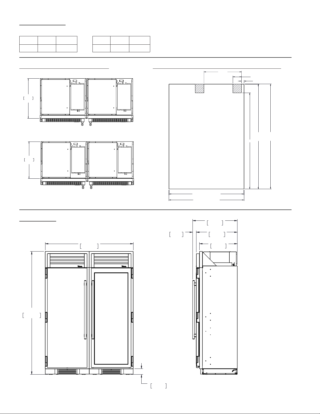
TR-36REF / TR-36REF
FLUSH OPENING DIMENSIONS PROUD OPENING DIMENSIONS
Width Depth Height
71¾" 23 ⁄" 84"
Width Depth Height
72¼" 25 ⁄" 84 ¼"
FLUSH VS. PROUD INSTALL
PLAN VIEW
71 3/4" PROUD INSTALL
72 1/4" FLUSH INSTALL
84"
PROUD
INSTALL
84 1/4"
FLUSH
INSTALL
77"
2"
8" TYP
36 1/8"
TR-36REF, TR-36REF
R
72 1/32"
1829mm
83 15/16"
2132mm
3 15/16"
100mm
25 25/32"
655mm
27 29/32"
709mm
30 15/32"
774mm
2 9/16"
65mm
TR-36REF,36REF
R
ROUGH OPENING & ELECTRICAL AREA
25 25/32"
655mm
FLUSH INSTALL
23 25/32"
604mm
PROUD INSTALL
TR-36REF,36REF
R
NOTE: DIMENSIONS MAY VARY BY ±
1
/
8
"
TEC_TM_009 Rev. B
December 31, 2019 Page 15 of 50
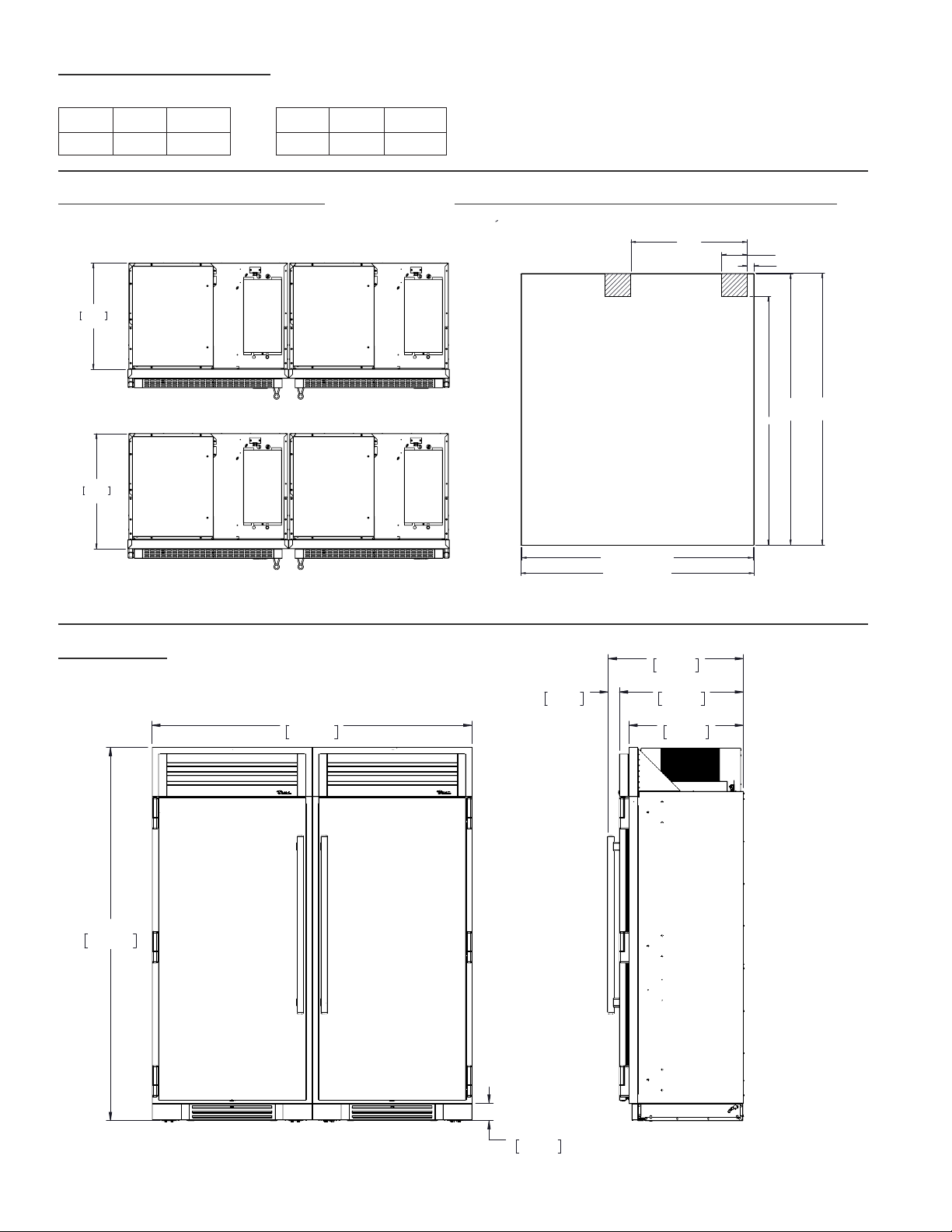
TR-36REF / TR-30REF
FLUSH OPENING DIMENSIONS PROUD OPENING DIMENSIONS
Width Depth Height
65¾" 23 ⁄" 84"
Width Depth Height
66¼" 25 ⁄" 84 ¼"
FLUSH VS. PROUD INSTALL
PLAN VIEW
65 3/4" PROUD INSTALL
66 1/4" FLUSH INSTALL
84"
PROUD
INSTALL
84 1/4"
FLUSH
INSTALL
77"
2"
8" TYP
30 1/8"
TR-36REF, TR-30REF
R
66 1/32"
1677mm
83 15/16"
2132mm
3 15/16"
100mm
25 25/32"
655mm
27 29/32"
709mm
30 15/32"
774mm
2 9/16"
65mm
TR-36REF,30RFRZ
ROUGH OPENING & ELECTRICAL AREA
25 25/32"
655mm
FLUSH INSTALL
23 25/32"
604mm
PROUD INSTALL
TR-36REF,30REF
R
NOTE: DIMENSIONS MAY VARY BY ±
1
/
8
"

TRUE RESIDENTIAL
®
TEC_TM_009 Rev. B
December 31, 2019 Page 16 of 50

TEC_TM_009 Rev. B
December 31, 2019 Page 17 of 50
17 - 26
PRESERVE THE MOMENT
®
a n t i - t i p B r a c k e t i n s t a l l a t i O n
l e v e l i n g t h e u n i t
J O i n i n g k i t i n s t a l l a t i O n
TRUE RESIDENTIAL
®
TEC_TM_009 Rev. B
December 31, 2019 Page 18 of 50
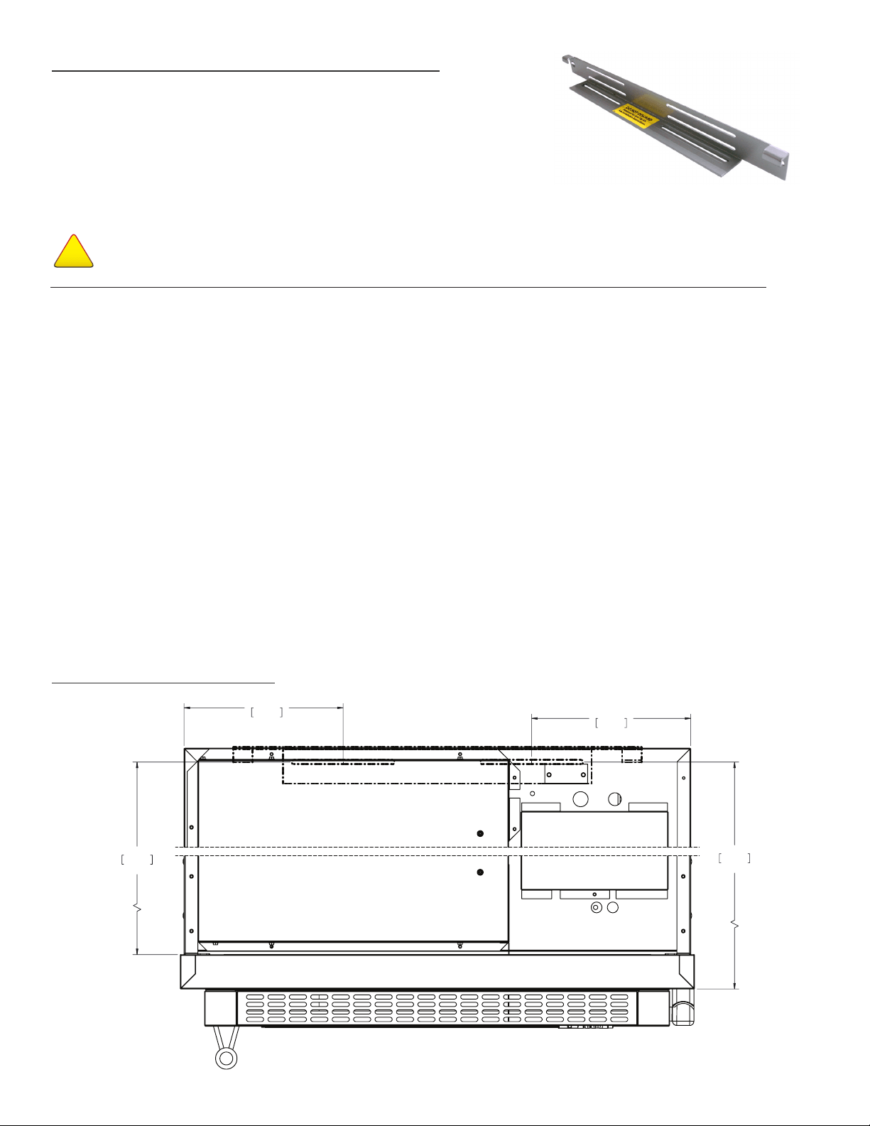
30 INCH / 36 INCH UNIT
"
KIT INCLUDES
• One (1) anti-tip bracket
• Four (4)
3
⁄16" masonry screws
• Eight (8) #12 –2" wood screws
• Twelve (12)
1
⁄4" washers
ANTI-TIP BRACKET KIT:
• One (1) anti-tip bracket (Figure 1.1)
• Four (4) masonry 3/16” screws
• Eight (8) wood #12 – 2” screws
• Twelve (12) 1/4” washers
FOR ALL FULL SIZE RESIDENTIAL MODELS, THE ANTI-
TIP BRACKET ENGAGES WITH THE REAR LEVELING
LEGS TO SECURE THE UNIT. FOLLOW THESE STEPS
TO SECURE THE BRACKET BEFORE MOVING THE
UNIT INTO FINAL OPERATING POSITION.
1. Determine final location of the unit. For a FLUSH
install, measure back 24-31/32” (Dimension A)
from the surrounding cabinetry. For a PROUD
install, measure back 22-31/32” (Dimension B)
from the surrounding cabinetry. For either type of
install, place the anti-tip bracket centered in the
rough opening.
2. Using the bracket as a guide, drill pilot holes into the
wall/floor. It is recommended to secure the bracket
to as many floor joists and wall studs as possible.
3. Using the provided screws and washers, secure the
bracket to the wall/floor. Adjust the rear rollers to
just above their lowest position and move the unit to
its final position. Raise the rear rollers a minimum
of 1/8” to engage the bracket.
FIGURE 1.1 - ANTI-TIP BRACKET
987036
5.19.17 AL
TRUE RESIDENTIAL REFRIGERATION
UPRIGHT ANTI-TIP BRACKET INSTALLATION
30 INCH UNIT
22 31/32"
583mm
PROUD INSTALL
24 31/32"
634mm
FLUSH INSTALL
9 9/32"
236mm
9 9/32"
236mm
C
L
C
L
TR-30REF-R-SG-A
R
NOTE: DIMENSIONS MAY VARY BY ±
1
/
8
”
WARNING: To avoid a hazard due to instability of
the appliance, it must be fixed in accordance with
the instructions.
AVERTISSEMENT: Pour éviter tout risque dú a
l´instabilité del l´appareil, vous devez le fixer
conformément aux instructions.
STEP 3
With the bracket as a guide, drill pilot holes into
the wall and/or floor.
NO T E: FOR INCREASED STABILITY, SECURE THE
BRACKET TO AS MANY JOISTS AND/OR STUDS AS
POSSIBLE.
STEP 4
With the provided hardware, secure the anti-tip
bracket.
STEP 5
Adjust the rear leveling rollers
1
⁄4 turn clockwise.
STEP 6
Slide the unit into place and hook the anti-tip
bracket into the castor assembly slots.
TOOLS REQUIRED
• Tape measure •
7
⁄16" socket
• Marking utensil • Phillips bit driver
•
1
⁄8" drill bit • Drill or ratchet
NOTES:
• DUE TO THE WEIGHT OF UNITS, IT IS RECOMMENDED TO CONSULT A FLOORING EXPERT
PRIOR TO INSTALLATION. THE FLOORING BENEATH THE UNIT SHOULD BE RATED TO SUPPORT
AT LEAST 150 POUNDS PER SQUARE FOOT.
• EIGHT (8) ¼-20 X 1" LAG BOLTS SECURING THE UNIT TO THE SKID DURING SHIPPING MAY
ALSO BE USED ON THE INSTALLATION OF THE ANTI-TIP BRACKET.
WARNING
!
TIP OVER HAZARD
A child or adult could tip the refrigerator resulting in property damage or bodily harm. Follow these instructions
to properly install the anti-tip device. If the unit is moved, verify the device is properly engaged before normal
usage of unit commences.
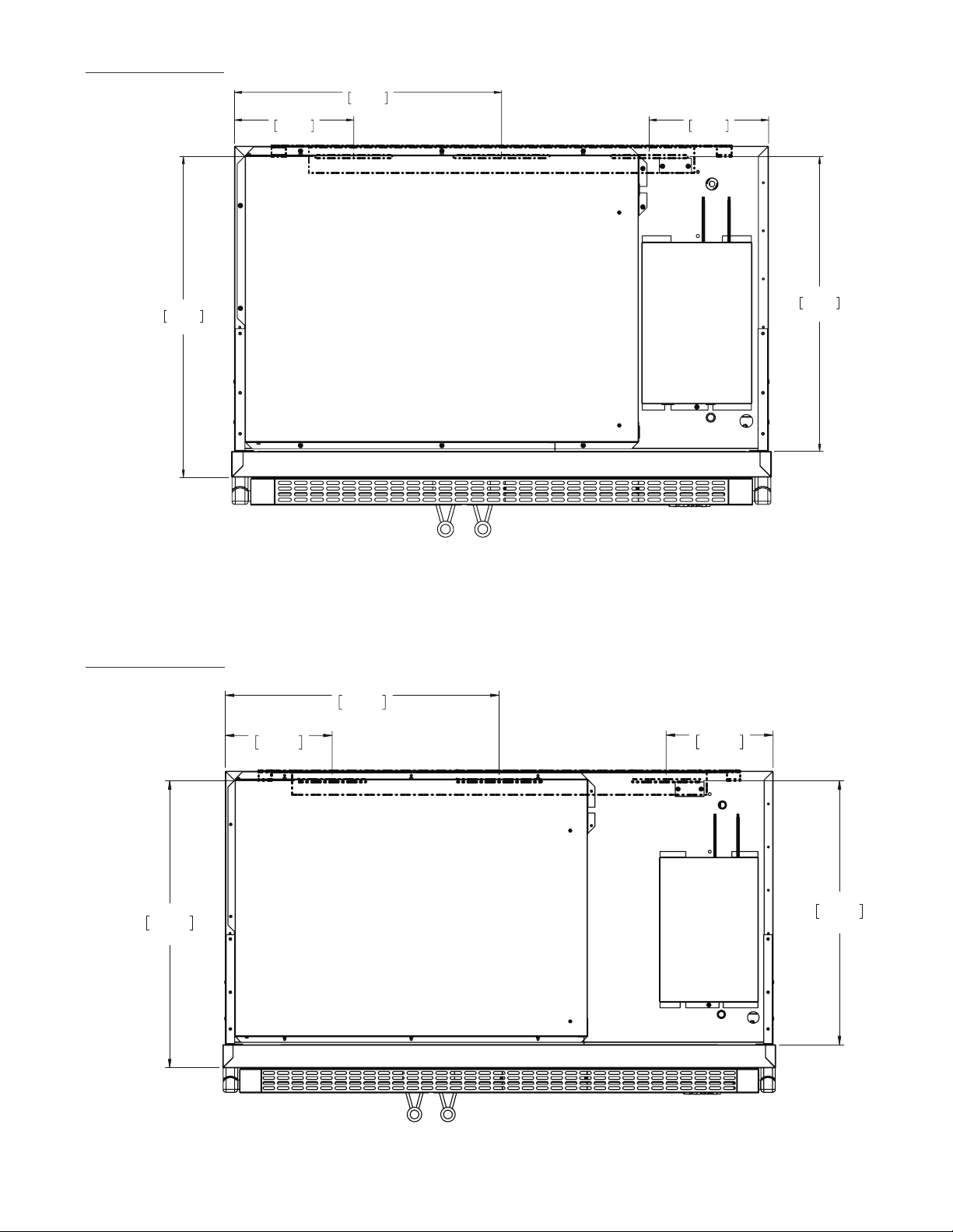
48 INCH UNIT
22 31/32"
583mm
PROUD INSTALL
24 31/32"
634mm
FLUSH INSTALL
9 9/32"
236mm
23 25/32"
604mm
9 9/32"
236mm
C
L
C
L
C
L
Anti-Tip Kit Install TR-48SBS-SS-B
R
NOTE: DIMENSIONS MAY VARY BY ±
1
/
8
”
42 INCH UNIT
24 31/32"
634mm
FLUSH INSTALL
22 31/32"
583mm
PROUD INSTALL
20 25/32"
528mm
9 9/32"
236mm
9 9/32"
236mm
C
L
C
L
C
L
Anti-Tip Kit Install TR-42SBS-SS-B
R
NOTE: DIMENSIONS MAY VARY BY ±
1
/
8
”
WARNING: To avoid a hazard from appliance instability, install the anti-tip bracket in accordance
with the instructions below.
UPRIGHT ANTI-TIP BRACKET INSTALLATION
BEFORE YOU BEGIN
Consult a flooring expert to confirm that the
flooring where the unit will be installed is rated for
at least 150 pounds per squate foot.
STEP 1
Measure and mark the depth of the bracket's
placement in the installation location.
• For a flush installation: 24
31
⁄32"
• For a proud installation: 22
31
⁄32"
STEP 2
Place and center the bracket at the measured
depth.
22 31/32"
583mm
PROUD INSTALL
24 31/32"
634mm
FLUSH INSTALL
9 9/32"
236mm
9 9/32"
236mm
℄
TR-30REF-R-SG-A
R
℄
*Dimensions may vary by ±1/8”
℄ = Center Line
–-– = Bracket Location
TEC_TM_009 Rev. B
December 31, 2019 Page 19 of 50
42 INCH UNIT
48 INCH UNIT
*Dimensions may vary by ±1/8”
*Dimensions may vary by ±1/8”
℄ = Center Line
–-– = Bracket Location
℄ = Center Line
–-– = Bracket Location
22 31/32"
583mm
PROUD INSTALL
24 31/32"
634mm
FLUSH INSTALL
9 9/32"
236mm
23 25/32"
604mm
9 9/32"
236mm
Anti-Tip Kit Install TR-48SBS-SS-B
R
℄℄℄
24 31/32"
634mm
FLUSH INSTALL
22 31/32"
583mm
PROUD INSTALL
20 25/32"
528mm
9 9/32"
236mm
9 9/32"
236mm
Anti-Tip Kit Install TR-42SBS-SS-B
R
℄℄℄
TRUE RESIDENTIAL
®
TEC_TM_009 Rev. B
December 31, 2019 Page 20 of 50
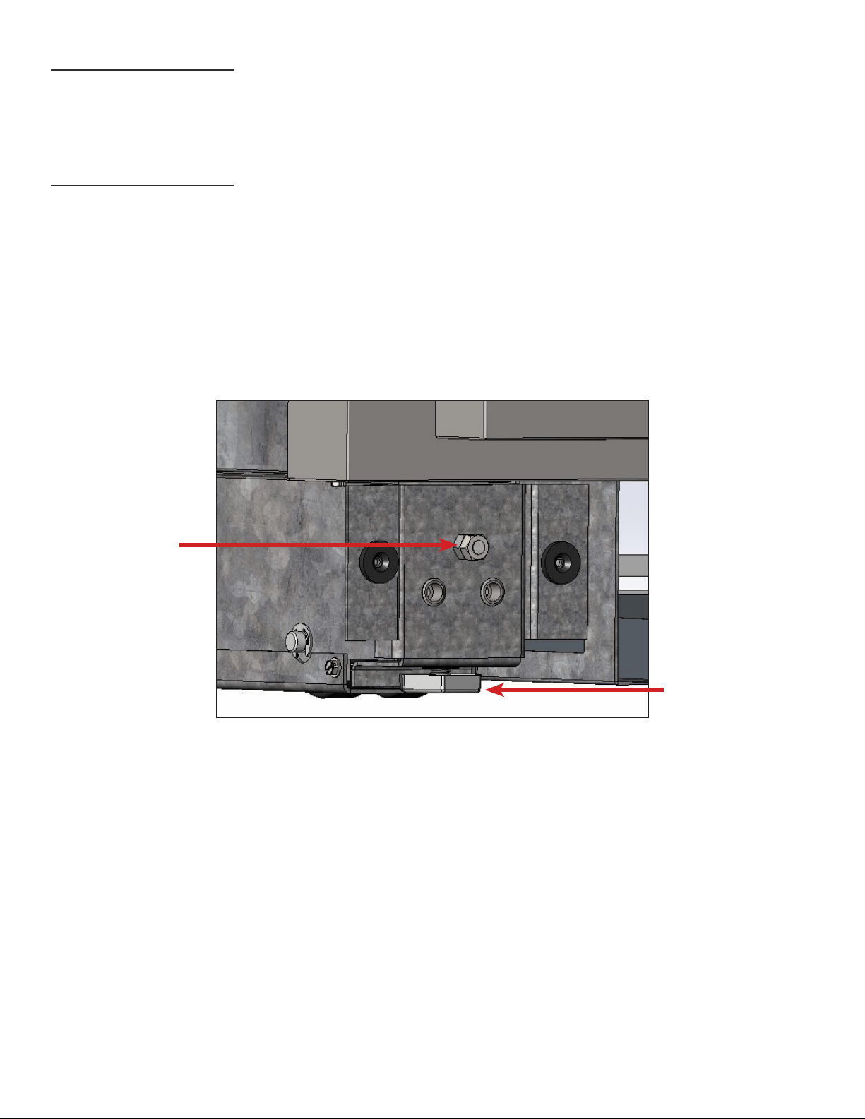
LEVELING THE UNIT
It is very important that the refrigerator sits level. This will insure that the doors will align and seal properly
and that the drain pans will not spill over.
TO LEVEL THE UNIT:
STEP 1. Place a level on the interior floor. Check and adjust so the unit is level from front to back, and left
to right.
STEP 2. Adjust the front legs using a set of pliers or a wrench.
STEP 3. Adjust the rear using a 7/16" socket and ratchet. Turn clockwise to raise the rear of the unit.
LEG ADJUSTMENTS
REAR LEG
ADJUSTMENT
FRONT LEG
ADJUSTMENT
TEC_TM_009 Rev. B
December 31, 2019 Page 21 of 50
5.18 SD
NO T E: MAKE SURE THE ANTI-TIP BRACKETS ARE INSTALLED PER INSTALLATION MANUAL INSTRUCTIONS.
EACH UNIT WILL ALSO NEED TO BE PROPERLY LEVELED PER INSTALLATION MANUAL INSTRUCTIONS.
TOOLS REQUIRED
• Phillips screwdriver
• Power drill
• 3/32" drill bit
• 7/16" socket
• 1/4" socket
• Pop rivet gun
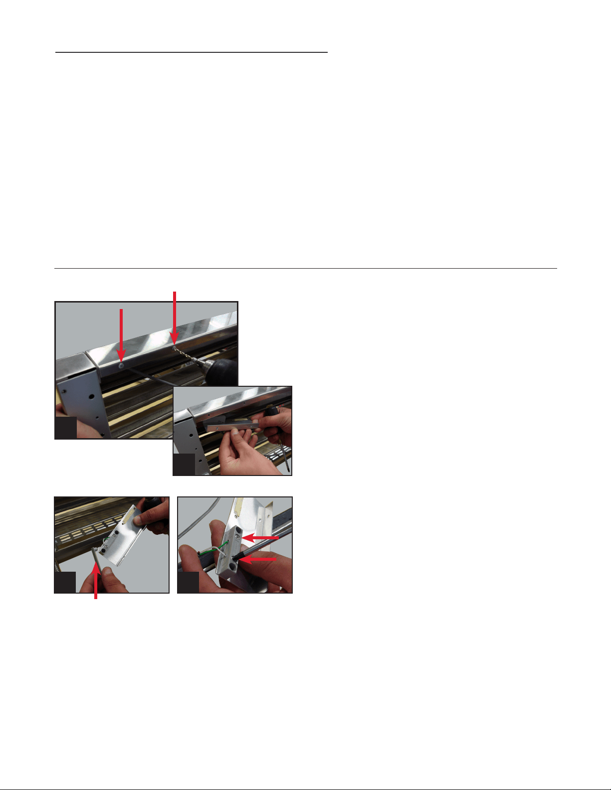
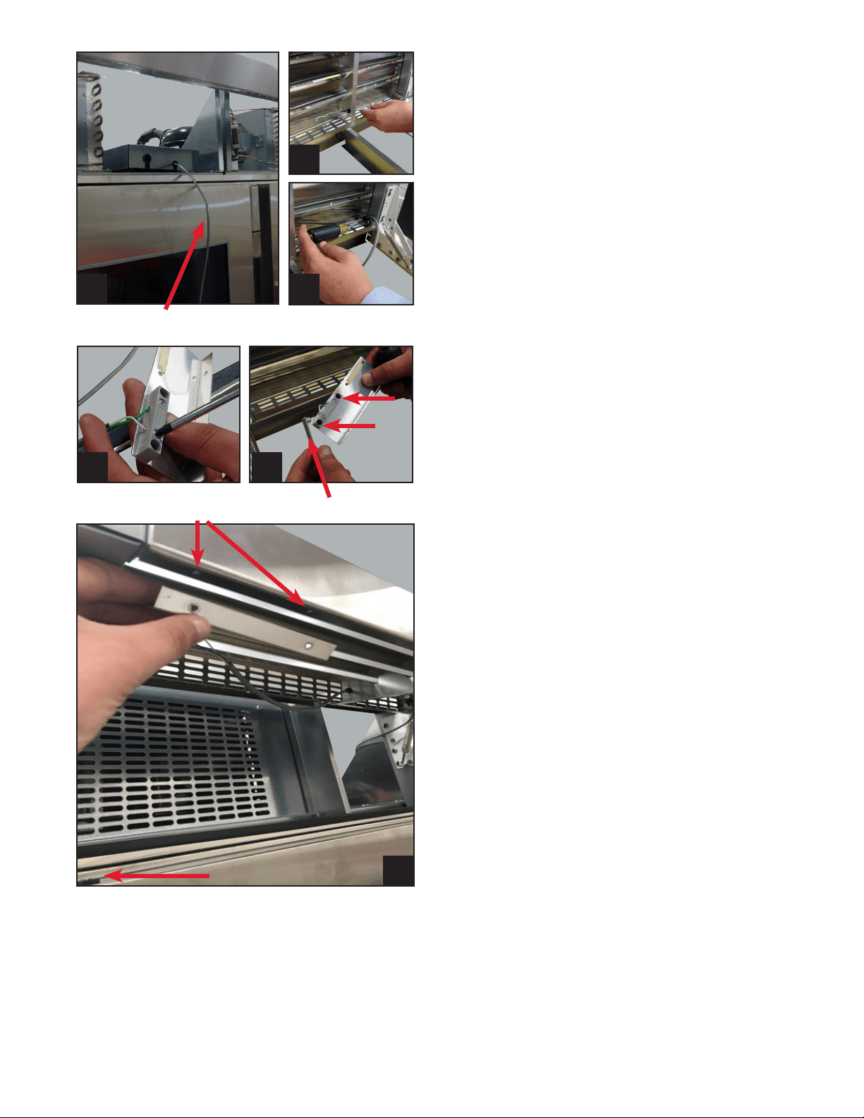
STEP 1
Unplug the cabinet(s).
STEP 2
Drill out the two pop rivets from the rain shield and
remove reed switch bracket.
Make note of the bracket orientation, and mount
the same way when reinstalling. When installed
properly, you should see the back side of the metal
bracket, and not the reed switch.
Images 2a & 2b.
STEP 3
Remove the plastic cover on the reed switch
to expose the two Phillips screws. Unscrew the
Phillips screws to disconnect the wires from the
reed switch.
Images 3a & 3b.
NOTE: SET BRACKET CONTAINING REED SWITCH
ASIDE FOR REINSTALLATION ON NEW GRILL.
2a
2b
3a 3b
Plastic Cover
KIT INCLUDES
A. 60" Grill or 90" Grill
B. Anti-sweat foam end panels
C. Pop rivets
D. Lower joining bracket
E. Joining bracket bolts
F. Joining bracket lock washers
TR-30 60"/90" JOINING KIT INSTALLATION
TRUE RESIDENTIAL
®
TEC_TM_009 Rev. B
December 31, 2019 Page 22 of 50
STEP 4
Remove the P-clip by unscrewing the 1/4" Phillips
screw and remove the wire from the P-clip.
Image 4.
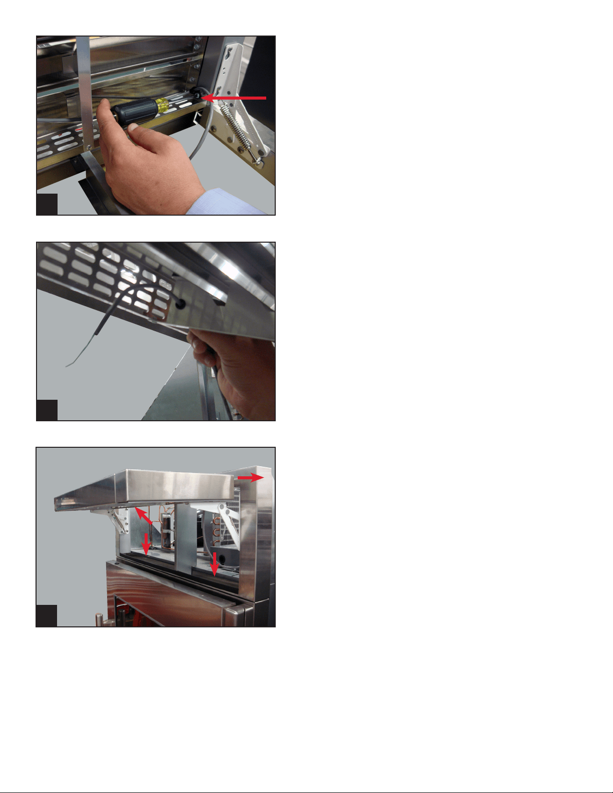
STEP 5
Pull reed switch wire though rain shield bushing
and set the wires aside for later use.
Image 5.
STEP 6: REMOVE RAIN SHIELD FROM CABINETS
Unscrew two Phillips screws facing down and two
on upper left and right side top of rain shield.
Remove the rain shield from the unit.
Image 6.
4
5
NOTE: ALL HARDWARE YOU REMOVE WILL BE
USED TO INSTALL THE NEW RAIN SHIELD.
NOTE: REPEAT STEPS 1-7 FOR EACH TR-30
UNIT YOU ARE INSTALLING.
6
TEC_TM_009 Rev. B
December 31, 2019 Page 23 of 50
STEP 8
Install anti-sweat foam end panels on sides of units
which will be joined together.
Image 8.
8
2 PADS USED 4 PADS USED
XX
✔ ✔ ✔
✔ ✔
X X
SIDE
FOAM PAD PLACEMENT
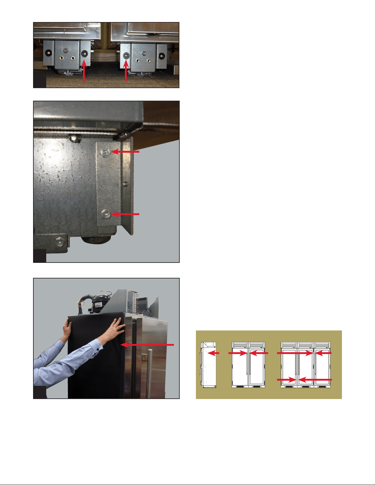
STEP 7
Remove the two 1/4" screws that hold the magnet
bracket for the louver grill on the left right side of
the units that are joining together. Remove both
screws and set the bracket aside. This bracket will
NOT reinstall with this application.
Images 7a & 7b.
NOTE: REINSTALL THE SCREWS THAT WERE
HOLDING THE BRACKET. THESE ARE USED TO
SUPPORT THE CASTOR ASSEMBLY HOUSING.
7b
7a
TRUE RESIDENTIAL
®
TEC_TM_009 Rev. B
December 31, 2019 Page 24 of 50
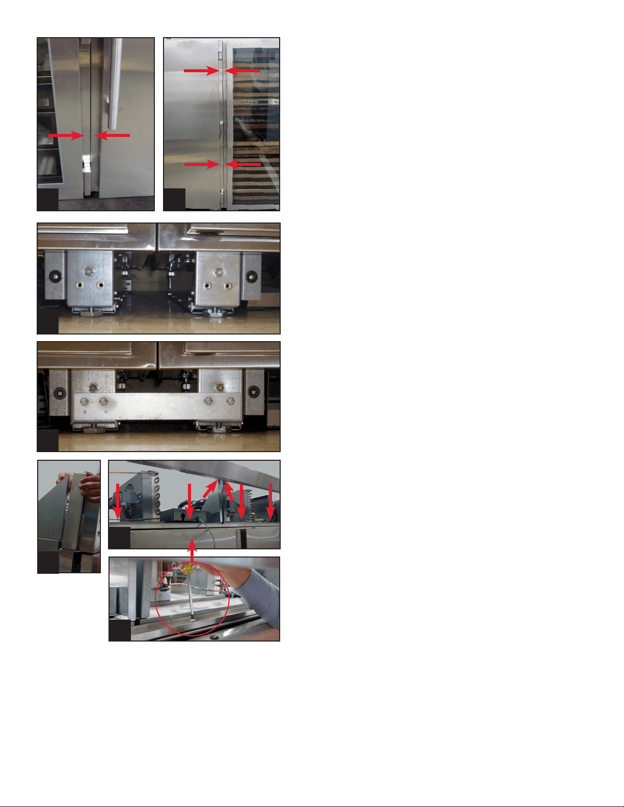
STEP 11: INSTALL NEW RAIN SHIELD
Install the 60 inch / 90 inch rain shield using the
hardware previously removed.
Image 11a, 11b & 11c.
NOTE: IT'S RECOMMENDED TWO OR MORE
PEOPLE ASSIST SETTING THE RAIN SHIELD IN
PLACE WHILE IT'S BEING SECURELY MOUNTED.
11c
11b
11a
STEP 9
Place units in front of opening where they will be
installed. Push units together and level the units
to make sure the flanges where the two units meet
are flush and the gap is consistent from top to
bottom.
Image 9a & 9b.
9a 9b
STEP 10
Once the units are pushed together and level,
install the bottom joining kit bracket with the four
7/16" bolts and lock washers.
Image 10a & 10b.
10a
10b
TEC_TM_009 Rev. B
December 31, 2019 Page 25 of 50
STEP 12
Route the reed switch wires through the P-clips
and bushings in the new grill.
Image 12a, 12b & 12c.
STEP 13
Reconnect door switch wires to reed switch (it
doesn’t matter which wire goes to each terminal)
and install the cover.
Image 13a & 13b.
STEP 14
Connect the reed switch to the new grill using
the pre drilled holes and pop rivets. Pay close
attention to how the doors are hinged, for this will
determine where to install the door switch bracket
into the louver grill. Each door has a magnet on the
handle side of the door. The reed switch bracket
will install in close proximity to this magnet.
Image 14.
STEP 15
Install the units into place by walking them into
the opening. Make final leveling adjustments if
needed. Close the louver grill, plug each unit in
and turn the power on by holding the power button
for 3 seconds.
STEP 16
Three minutes after plugging in the units, open
and close each door individually, making sure
the evaporator fans and lights are shutting off
when the door is opened and closed. Note: all
units have the ability to leave the lights on all the
time, bypassing the door switch. However, the
evaporator (interior) fans should always turn on
and off with door openings. You should also hear a
low-pitched click from the control board area when
the door is opened and shut.
12a
14
NOTE: P-CLIPS WILL ONLY BE USED ON EACH
END OF THE NEW GRILL NOT IN THE CENTER
(APPLIES TO 90 INCH ONLY).
12c
12b
Reed Switch Wire
13a 13b
Plastic Cover
Pre-drilled Holes in Louver Grill
Magnet

TRUE RESIDENTIAL
®
TEC_TM_009 Rev. B
December 31, 2019 Page 26 of 50

TEC_TM_009 Rev. B
December 31, 2019 Page 27 of 50
REFRIGERATOR AND FREEZER
B a s i c e l e c t r O n i c O p e r a t i O n s
s h O w r O O m m O D e
27 - 34
PRESERVE THE MOMENT
®
TRUE RESIDENTIAL
®
TEC_TM_009 Rev. B
December 31, 2019 Page 28 of 50
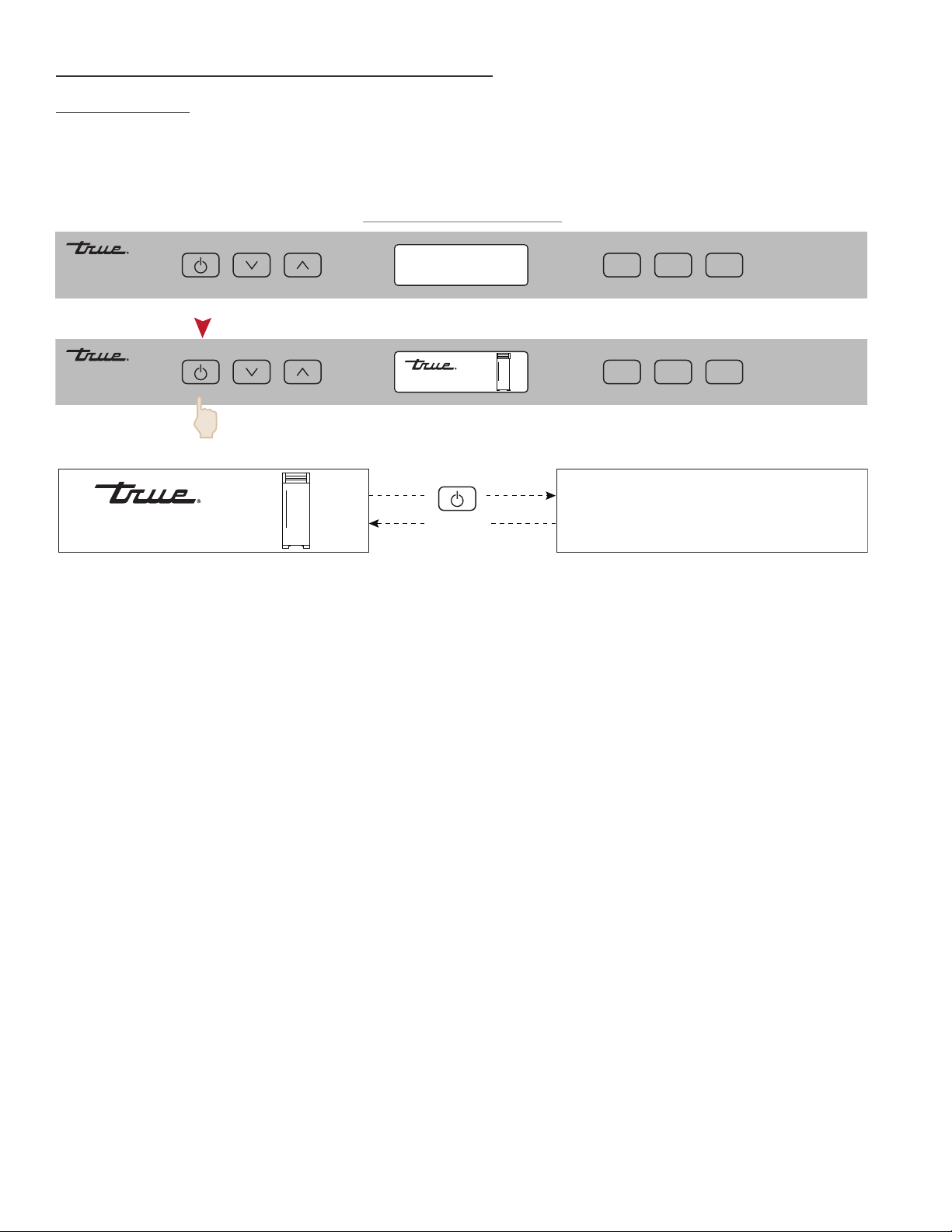
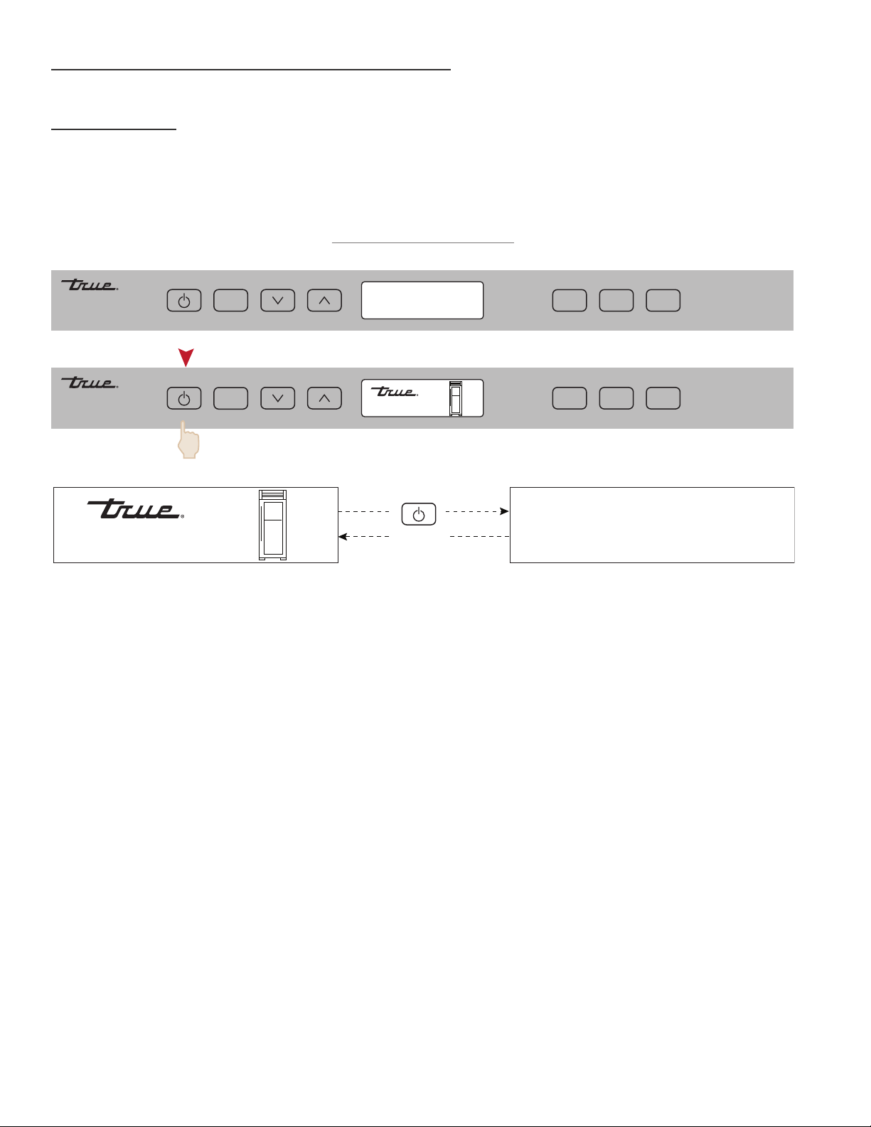
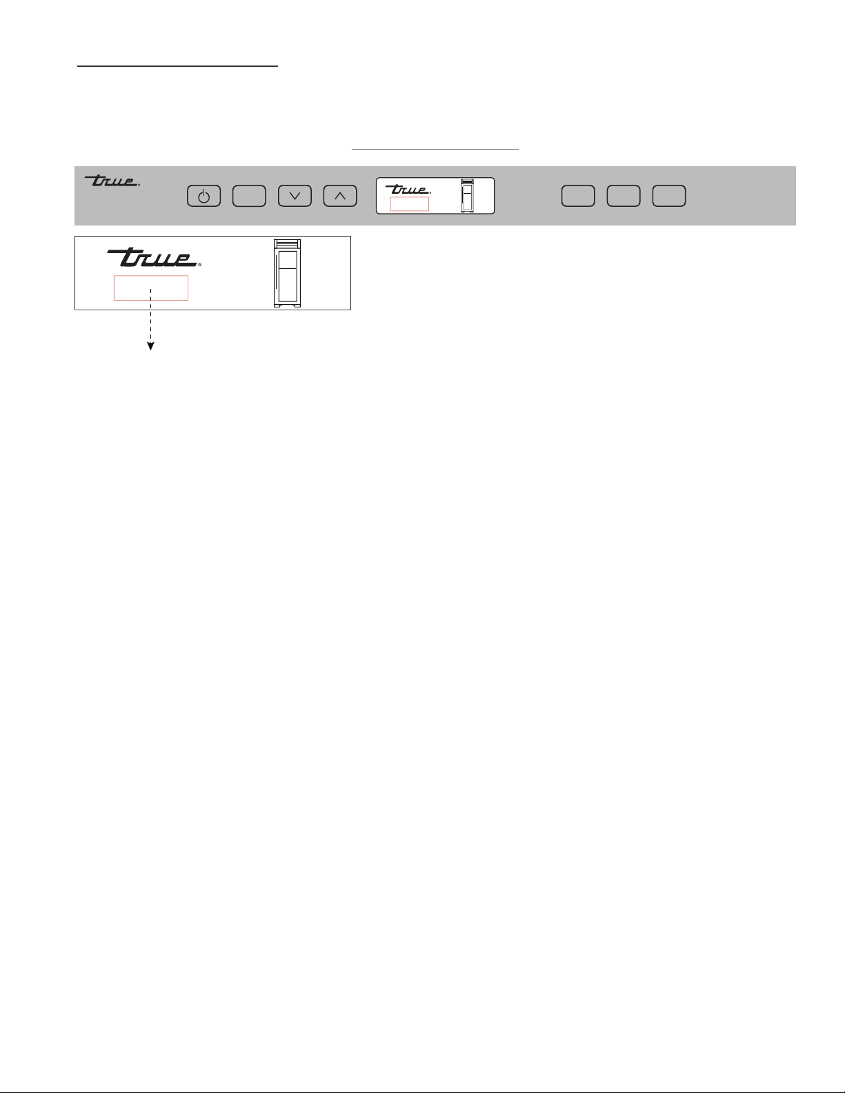
BASIC ELECTRONIC CONTROL OPERATIONS
UNIT ON/OFF
All units are shipped in ON Mode. When electricity is supplied to the appliance, a short power up diagnostics
test is initiated followed by one audible beep, the lights energizing and temperature readings appearing in the
LCD.
(2 sec)
MODE
LIGHT
ALARM
MODE
LIGHT
ALARM
38°F
OFF
38°F
OFF
HOME SCREEN ON / OFF
PLEASE NOTE THAT THOUGH POSSIBLE TO DISPLAY TEMPERATURES IN FAHRENHEIT OR
CELSIUS, IN MOST CASES FAHRENHEIT READINGS ARE SHOWN IN THIS MANUAL.
TEC_TM_009 Rev. B
December 31, 2019 Page 29 of 50
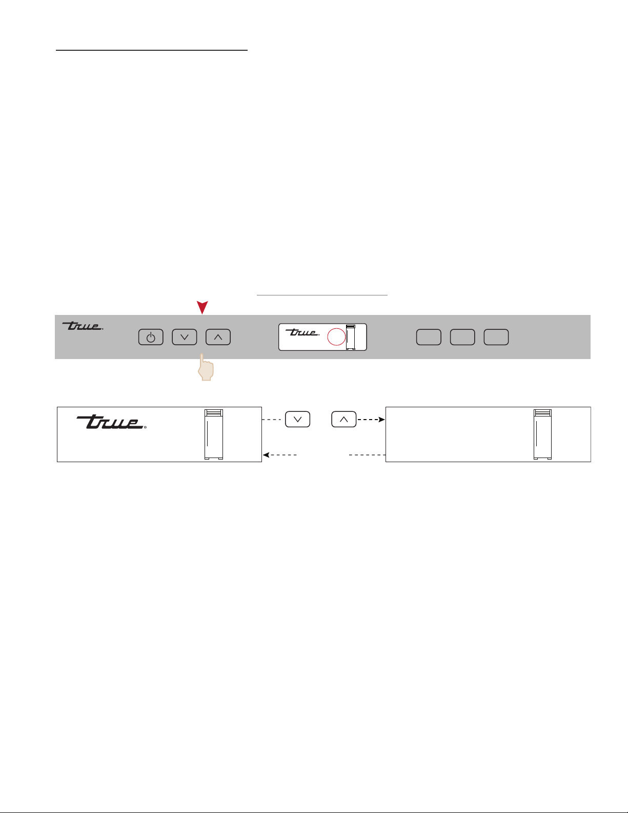
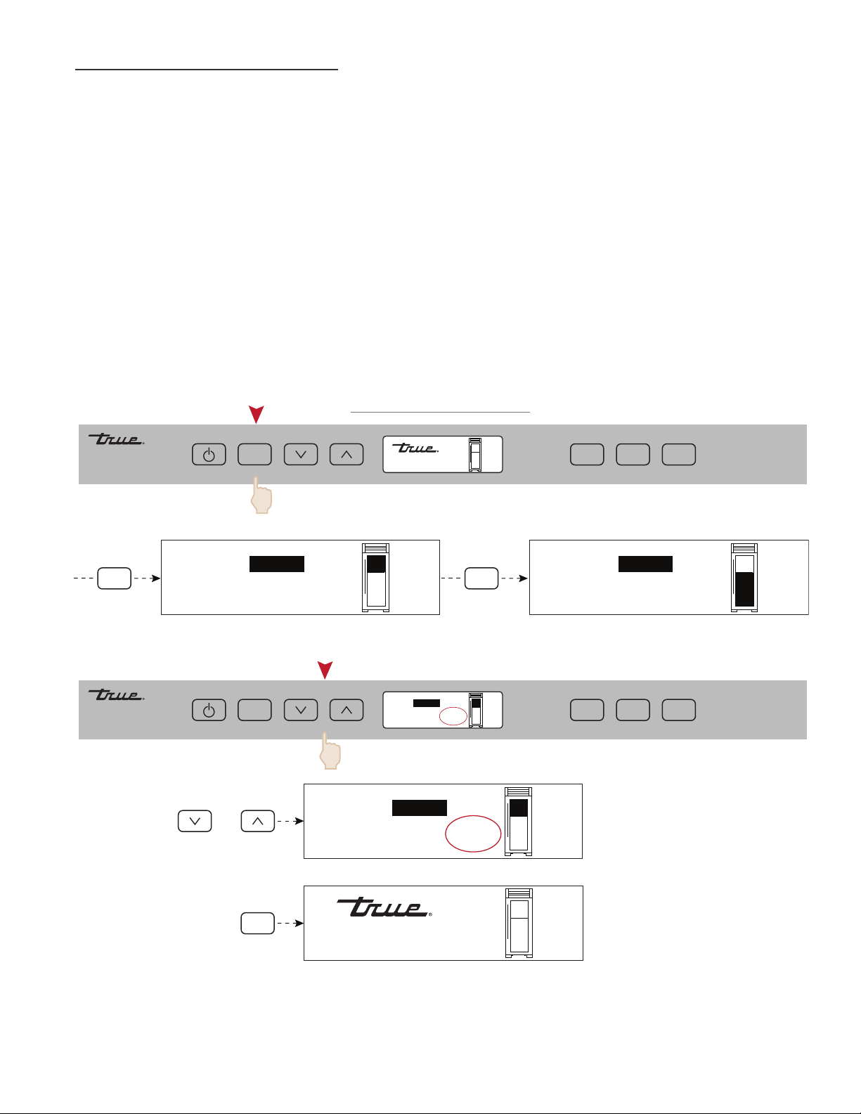
TEMPERATURE ADJUSTMENT
To adjust set-point, press DOWN or UP key on control panel in multiple key strokes until the desired set-point
is achieved. Each key stroke equals a one degree change and is accompanied by an audible beep. When the
desired set-point is reached wait 5 seconds until display resumes “HOME” screen.
NOTES:
• THE TEMPERATURE RANGE IN A FREEZER ZONE IS -4°F (-20°C) TO +4°F (-16°C).
• THE TEMPERATURE RANGE IN A REFRIGERATOR ZONE IS +34°F (+1°C) TO +42°F (+6°C).
• INITIAL FACTORY SET-POINTS ARE 0°F (-18°C) IN A FREEZER ZONE AND 38°F (3°C) IN A
REFRIGERATOR ZONE.
• THE INITIAL STROKE OF THE UP OR DOWN KEY WILL CHANGE THE PREVIOUS SET-POINT BY
ONE DEGREE.
MODE
LIGHT
ALARM
38°F
No Action
(5 sec)
OR
38°F
38°F
REFRIGERATOR
REFRIGERATOR 38ºF / FREEZER 0ºF
SET POINT NAVIGATION
TRUE RESIDENTIAL
®
TEC_TM_009 Rev. B
December 31, 2019 Page 30 of 50
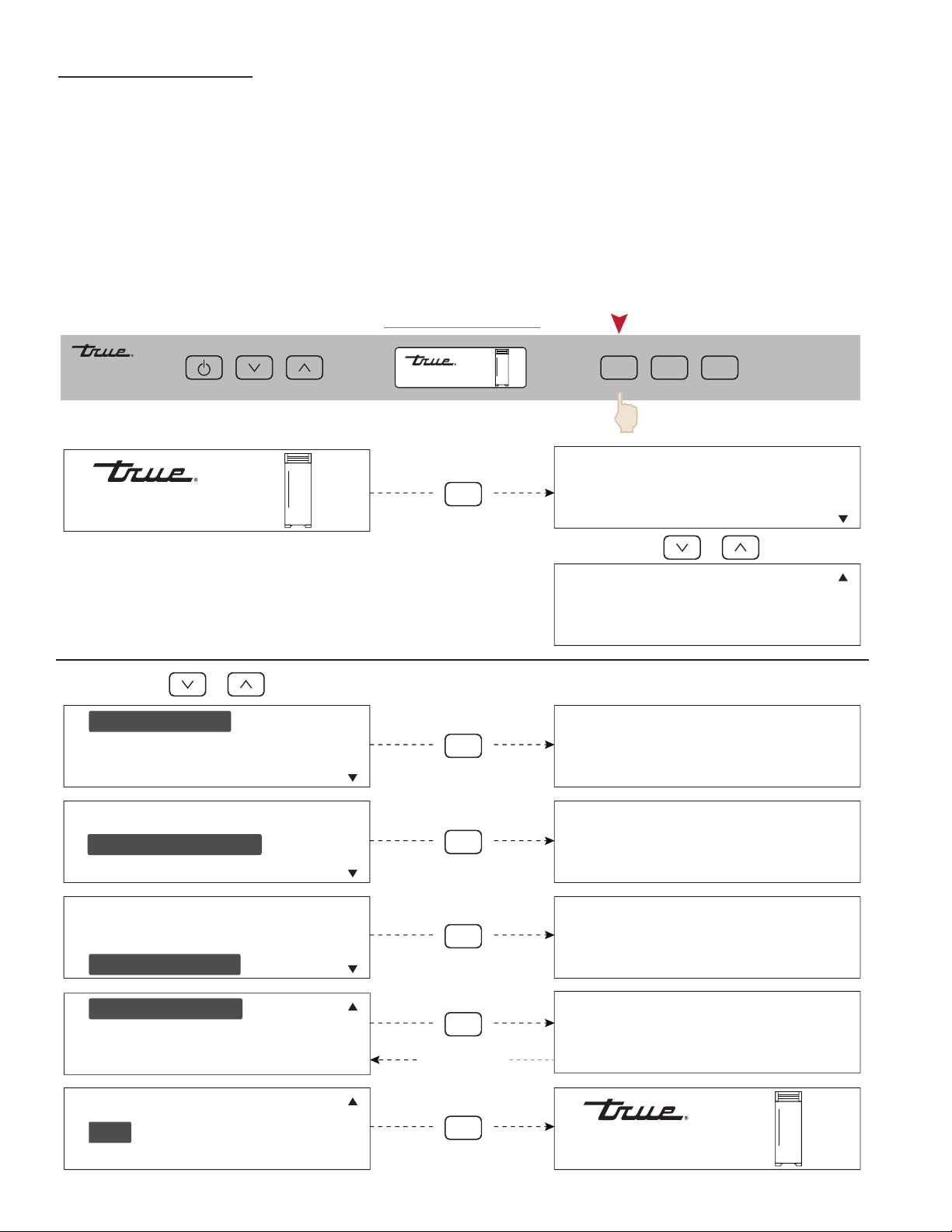
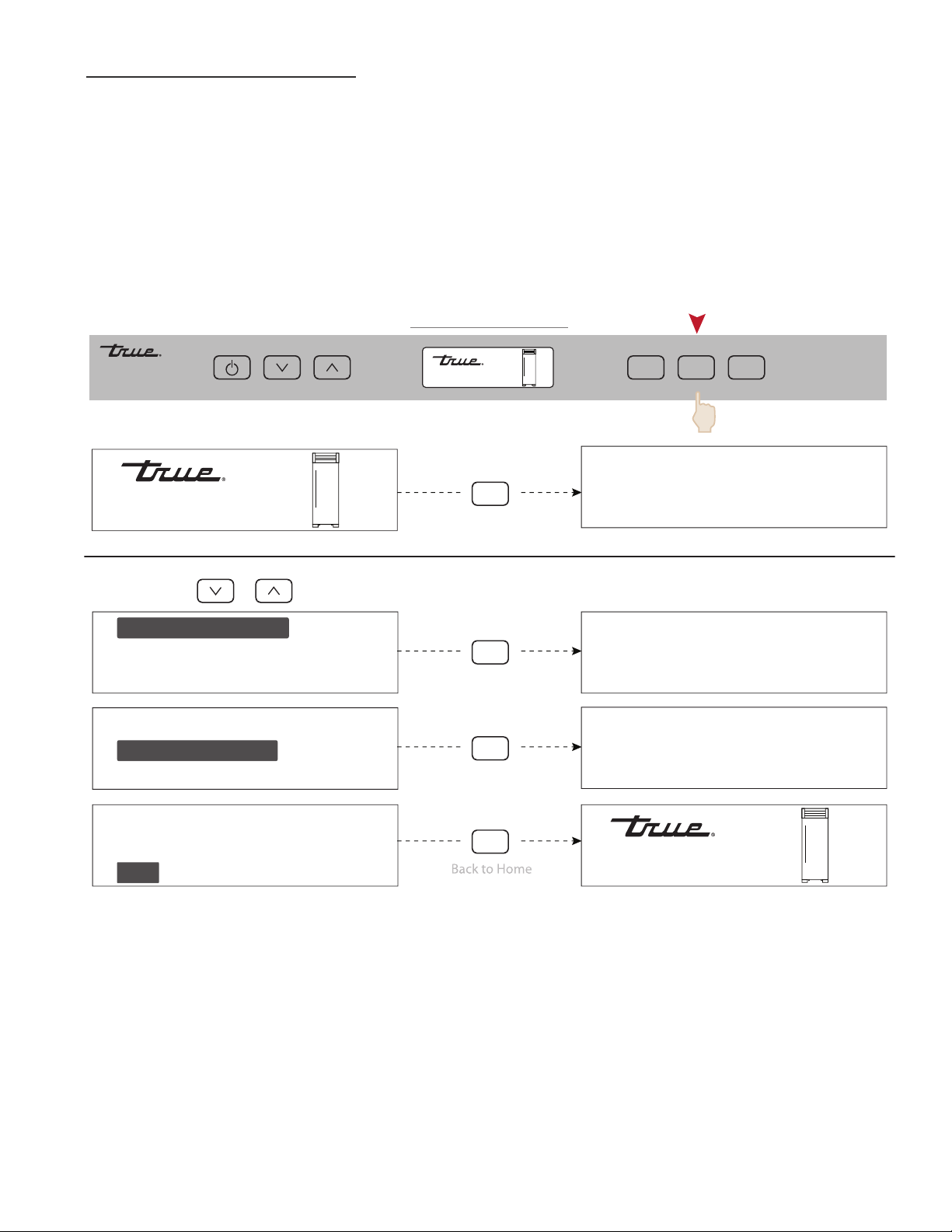
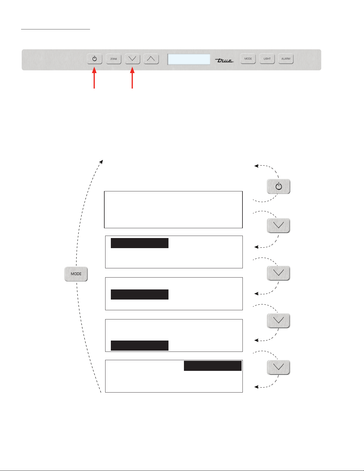
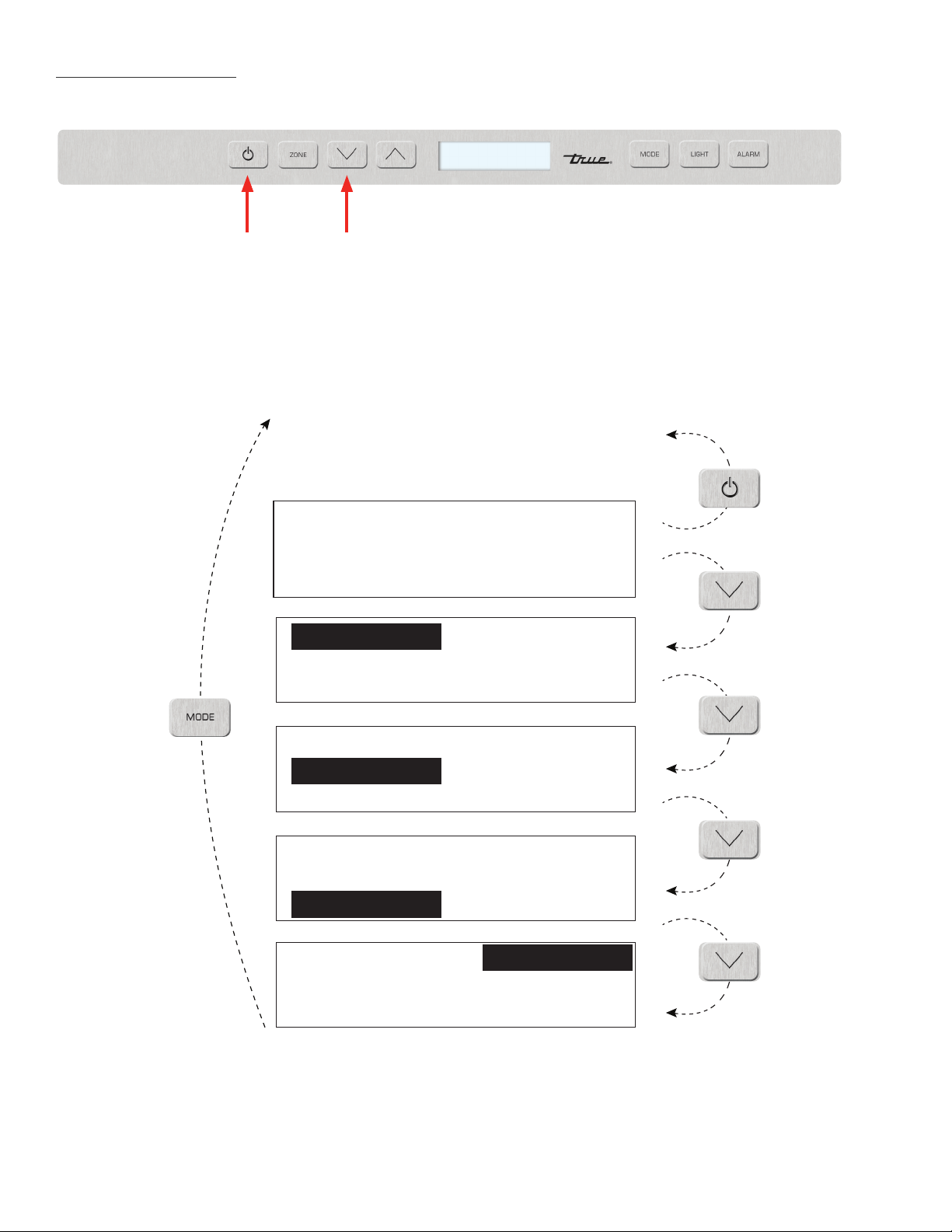
MODE NAVIGATION
The following pages illustrate unique customer input operations performed at the control panel. The input
operations described are: HOLIDAY MODE, TEMPERATURE UNIT SELECTION MODE AND VACATION MODE.
NOTES: (HOLIDAY MODE)
• SET-POINTS CANNOT BE CHANGED AND MANUAL DEFROST CANNOT BE INITIATED.
• THE FOLLOWING HOLDS TRUE IN ACCORDANCE WITH STAR-K REQUIREMENTS:
• Freezer defrosting functions will convert to a fixed time base sequence.
• The compartment/zone thermistors will still detect cut-in and cut-out, which is the determining factor to
start/stop the cooling process, but there will be a random sixteen (16) to twenty-one (21) second delay
before cooling begins/ends.
• The phrase “HOLIDAY MODE ACTIVE” in the LCD remains energized when the door is closed.
MODE
LIGHT
ALARM
38°F
MODE
38°F
TEMPERATURE ºF
VACATION MODE
HOLIDAY MODE
MODE
HOLIDAY MODE ACTIVE
PRESS ANY KEY TO EXIT
TEMPERATURE ºF
VACATION MODE
HOLIDAY MODE
MODE
TEMPERATURE IS
FAHRENHEIT
PRESS ANY KEY TO EXIT
TEMPERATURE ºF
VACATION MODE
HOLIDAY MODE
MODE
VACATION MODE ACTIVE
MODE ENDS ON NEXT DOOR
OPENING
NO SERVICE REQUIRED
TEMPERATURE ºF
VACATION MODE
HOLIDAY MODE
EXIT
SERVICE REPORT
R
etu
rn
f
r
om
Se
rvi
ce
Sc
r
een
MODE
EXIT
SERVICE REPORT
B
ac
k
to
H
o
m
e
Sc
r
ee
n
38°F
MODE
EXIT
SERVICE REPORT
MODE NAVIGATION
TEC_TM_009 Rev. B
December 31, 2019 Page 31 of 50
ACCENT LIGHTING SYSTEM
All models are equipped with an accent lighting system in the refrigerator and or freezer compartment(s). To
energize the accent lighting system, press the LIGHT key, and navigate to the corresponding compartment,
DOOR or ON will appear in the LCD indicating the accent lights are enabled. With the accent lighting system
ON, the LED’s will be energized and stay illuminated when the door is closed, in the DOOR position the lighting
system will only be energized with the door opening.
NOTE:
• WHEN LIGHTS ARE PLACED IN “ON” MODE, LIGHTS WILL NOT FADE-UP WHEN DOOR OPENS.
MODE
LIGHT
LIGHT
LIGHT
LIGHT
LIGHT
ALARM
38°F
38°F
BACKLIGHT DOOR
EXIT
LIGHT MODE DOOR
BACKLIGHT DOOR
EXIT
LIGHT MODE DOOR
BACKLIGHT DOOR
EXIT
LIGHT MODE DOOR
BACKLIGHT DOOR
EXIT
LIGHT MODE DOOR
LIGHT MODE ON
BACKLIGHT ON
S
creen
38°F
LIGHT NAVIGATION
TRUE RESIDENTIAL
®
TEC_TM_009 Rev. B
December 31, 2019 Page 32 of 50
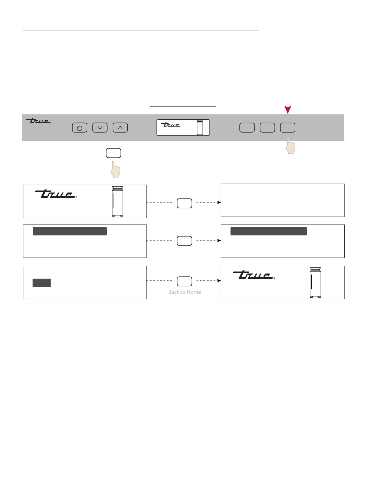
ALARM NAVIGATION (DOOR AJAR ALARM FEATURE ON/OFF)
All Residential Series units are equipped with a door ajar alarm feature. To enable the door ajar alarm, press
the ALARM key on the control panel and “DOOR ALARM IS ON” will appear in the LCD indicating the alarm is
enabled. With the alarm enabled, the notification icons will appear and an audible alarm will beep continuously
whenever a door is left open for more than 5 minutes. To disable the door ajar alarm, press the ALARM key
again and “DOOR ALARM IS OFF” will appear in the LCD.
MODE
LIGHT
ALARM
ALARM
ALARM
ALARM
ALARM
38°F
38°F
EXIT
DOOR ALARM IS ON
EXIT
DOOR ALARM IS ON
S
cree
n
*TO STOP ALARM BUZZER PRESS
38°F
EXIT
DOOR ALARM IS OFF
EXIT
DOOR ALARM IS OFF
refrigerator
door ajar
*
ALARM NAVIGATION
TEC_TM_009 Rev. B
December 31, 2019 Page 33 of 50
MODE
LIGHT
ALARM
38°F
38°F
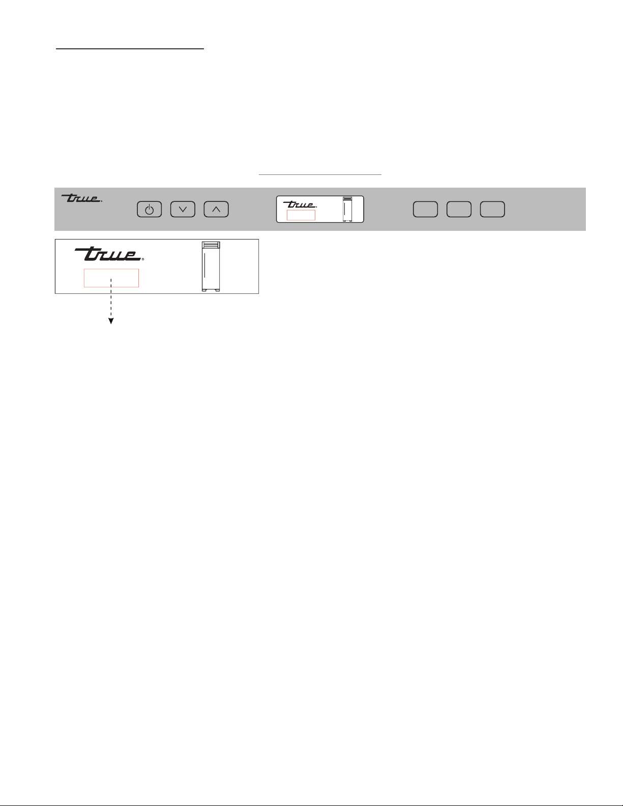
•high temp
•defrost
•showroom mode
•communication error
•service required
•door alarm
NOTIFICATION ALERTS
NOTIFICATION ALERTS
The diagrams on these pages illustrate what a customer may see in the LCD if the appliance needs attention.
TRUE RESIDENTIAL
®
TEC_TM_009 Rev. B
December 31, 2019 Page 34 of 50
SHOWROOM MODE
When in Showroom Mode all cooling and defrosting functions are disabled, but the lighting system and
door ajar alarm system remain operational, and the LCD will show the set-points.
NOTES:
• For demonstration purposes, all the navigation menus are display only and inactive.
E x it
REf Ri g E R ato R
REf Ri g E R ato R
REf Ri g E R ato R
Showroom Mode Off
Showroom Mode Off
warning this model is for
service use only
press power to exit or
down to continue
(HOME SCREEN)
Showroom Mode Of
fRE E z E R
E x it
REf Ri g E R ato R
Showroom Mode Off
fRE E z E R
fRE E z E R
fRE E z E R
E x it
E x it
Showroom Mode On

TEC_TM_009 Rev. B
December 31, 2019 Page 35 of 50
DUAL ZONE
B a s i c e l e c t r O n i c O p e r a t i O n s
s h O w r O O m m O D e
35 - 42
PRESERVE THE MOMENT
®
TRUE RESIDENTIAL
®
TEC_TM_009 Rev. B
December 31, 2019 Page 36 of 50
BASIC ELECTRONIC CONTROL OPERATIONS
UNIT ON/OFF
All units are shipped in ON Mode. When electricity is supplied to the appliance, a short power up diagnostics
test is initiated followed by one audible beep, the lights energizing and temperature readings appearing in the
LCD.
(2 sec)
MODE
LIGHT
ALARM
ZONE
MODE
LIGHT
ALARM
55°F
45°F
OFF
55°F
45°F
OFF
ZONE
HOME SCREEN ON / OFF
PLEASE NOTE THAT THOUGH POSSIBLE TO DISPLAY TEMPERATURES IN FAHRENHEIT OR
CELSIUS, IN MOST CASES FAHRENHEIT READINGS ARE SHOWN IN THIS MANUAL.
TEC_TM_009 Rev. B
December 31, 2019 Page 37 of 50
TEMPERATURE ADJUSTMENT
To adjust set-point, press the ZONE button to highlight the zone for adjustment. Once the zone is highlighted,
press DOWN or UP key on the control panel in multiple key strokes until the desired set-point is achieved. Each
key stroke equals a one degree change and is accompanied by an audible beep. When the desired set-point is
reached, press the ZONE button to return to “HOME” screen.
NOTES:
• THE TEMPERATURE RANGES FROM 40°F (4.4°C) TO 65°F (18.3°C) IN EITHER SECTION OF
THE UNIT
• INITIAL FACTORY SET-POINTS ARE 55°F (12.7°C) IN THE UPPER ZONE AND 45°F (7.2°C) IN
THE LOWER ZONE.
• THE INITIAL STROKE OF THE UP OR DOWN KEY WILL CHANGE THE PREVIOUS SET-POINT BY
ONE DEGREE.
MODE
LIGHT
ALARM
55°F
45°F
ZONE
MODE
LIGHT
ALARM
ZONE
ZONEZONE
ZONE 1 UPPER
55°F
ZONE 2 LOWER
45°F
ZONE 1 UPPER
55°F
ZONE
ZONE 1 UPPER
55°F
OR
55°F
45°F
UPPER ZONE 55ºF / LOWER ZONE 45ºF
SET POINT NAVIGATION

TRUE RESIDENTIAL
®
TEC_TM_009 Rev. B
December 31, 2019 Page 38 of 50
MODE NAVIGATION
The following pages illustrate unique customer input operations performed at the control panel. The input
operations described are: HOLIDAY MODE, TEMPERATURE UNIT SELECTION MODE AND VACATION MODE.
NOTES: (HOLIDAY MODE)
• SET-POINTS CANNOT BE CHANGED AND MANUAL DEFROST CANNOT BE INITIATED.
• THE FOLLOWING HOLDS TRUE IN ACCORDANCE WITH STAR-K REQUIREMENTS:
- Freezer defrosting functions will convert to a fixed time base sequence.
- The compartment/zone thermistors will still detect cut-in and cut-out, which is the determining factor to
start/stop the cooling process, but there will be a random sixteen (16) to twenty-one (21) second delay
before cooling begins/ends.
- The phrase “HOLIDAY MODE ACTIVE” in the LCD remains energized when the door is closed.
MODE
TEMPERATURE ºF
VACATION MODE
HOLIDAY MODE
MODE
HOLIDAY MODE ACTIVE
PRESS ANY KEY TO EXIT
TEMPERATURE ºF
VACATION MODE
HOLIDAY MODE
MODE
TEMPERATURE IS
FAHRENHEIT
PRESS ANY KEY TO EXIT
TEMPERATURE ºF
VACATION MODE
HOLIDAY MODE
MODE
VACATION MODE ACTIVE
MODE ENDS ON NEXT DOOR
OPENING
NO SERVICE REQUIRED
TEMPERATURE ºF
VACATION MODE
HOLIDAY MODE
EXIT
SERVICE REPORT
Return
f
ro
m
S
ervice
S
cree
n
MODE
EXIT
SERVICE REPORT
B
ac
k
to
H
o
m
e
Sc
r
ee
n
MODE
EXIT
SERVICE REPORT
MODE
LIGHT
ALARM
55°F
45°F
ZONE
55°F
45°F
55°F
45°F
MODE NAVIGATION
TEC_TM_009 Rev. B
December 31, 2019 Page 39 of 50
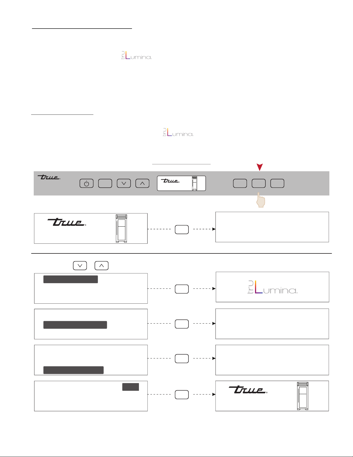
ACCENT LIGHTING SYSTEM
All models are equipped with an accent lighting system in the refrigerator and or freezer compartment(s).
To change the accent lighting color, press the LIGHT key once until you see “CHANGE COLOR” press the
LIGHT button once again to start . . Press the “LIGHT” button once again to lock in your desired
color. DOOR or ON will appear in the LCD indicating the accent lights are enabled. With the accent lighting
system ON, the LED’s will be energized and stay illuminated when the door is closed, in the DOOR position the
lighting system will only be energized with the door opening.
COLOR CHANGE
To change colors of the LED’s, press the light button once until you see “CHANGE COLOR”. Press the “LIGHT”
button once and release to start cycling through . . Press the “LIGHT” button again to hold the color
option you desire.
LIGHT
LIGHT
LIGHT
LIGHT
LIGHT MODE DOOR
BACKLIGHT DOOR
EXIT
EXIT
EXIT
EXIT
CHANGE COLOR
LIGHT MODE DOOR
BACKLIGHT DOOR
CHANGE COLOR
LIGHT MODE DOOR
BACKLIGHT DOOR
CHANGE COLOR
LIGHT MODE DOOR
BACKLIGHT DOOR
CHANGE COLOR
ON
LIGHT
EXIT
LIGHT MODE DOOR
BACKLIGHT DOOR
CHANGE COLOR
Back to Home
S
creen
ON
MODE
LIGHT
ALARM
55°F
45°F
ZONE
55°F
45°F
55°F
45°F
LIGHT NAVIGATION
TRUE RESIDENTIAL
®
TEC_TM_009 Rev. B
December 31, 2019 Page 40 of 50
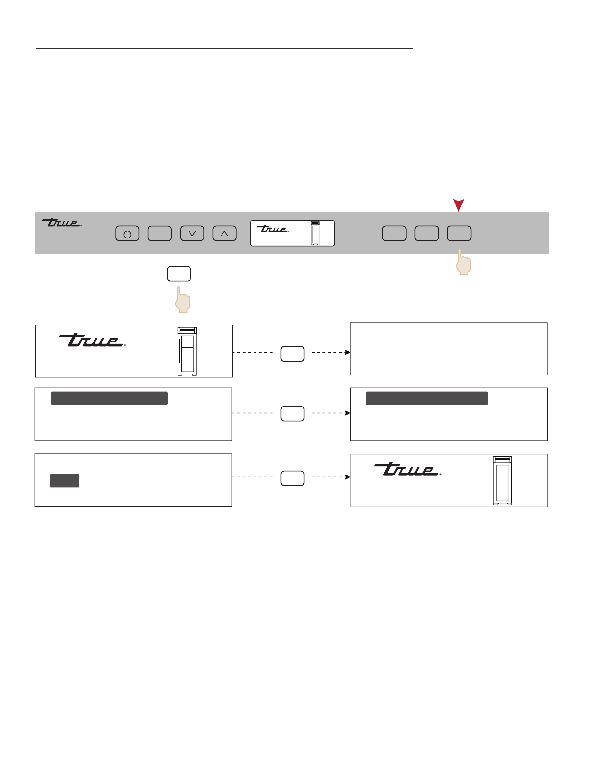
ALARM NAVIGATION (DOOR AJAR ALARM FEATURE ON/OFF)
All Residential Series units are equipped with a door ajar alarm feature. To enable the door ajar alarm, press
the ALARM key on the control panel and “DOOR ALARM IS ON” will appear in the LCD indicating the alarm is
enabled. With the alarm enabled, the notification icons will appear and an audible alarm will beep continuously
whenever a door is left open for more than 5 minutes. To disable the door ajar alarm, press the ALARM key
again and “DOOR ALARM IS OFF” will appear in the LCD.
ALARM
ALARM
ALARM
ALARM
EXIT
DOOR ALARM IS ON
EXIT
DOOR ALARM IS ON
B
ac
k
to
H
o
m
e
Sc
r
ee
n
*TO STOP ALARM BUZZER PRESS
EXIT
DOOR ALARM IS OFF
EXIT
DOOR ALARM IS OFF
55°F
45°F
55°F
45°F
refrigerator
door ajar
*
MODE
LIGHT
ALARM
55°F
45°F
ZONE
ALARM NAVIGATION
TEC_TM_009 Rev. B
December 31, 2019 Page 41 of 50
55°F
45°F
MODE
LIGHT
ALARM
55°F
45°F
ZONE
•high temp
•defrost
•showroom mode
•communication error
•service required
•door alarm
•zone 1 upper high temp
•zone 2 lower high temp
NOTIFICATION ALERTS
NOTIFICATION ALERTS
The diagrams on these pages illustrate what a customer may see in the LCD if the appliance needs attention.
TRUE RESIDENTIAL
®
TEC_TM_009 Rev. B
December 31, 2019 Page 42 of 50
SHOWROOM MODE
When in Showroom Mode all cooling and defrosting functions are disabled, but the lighting system and
door ajar alarm system remain operational, and the LCD will show the set-points.
NOTES:
• For demonstration purposes, all the navigation menus are display only and inactive.
E x it
REf Ri g E R ato R
REf Ri g E R ato R
REf Ri g E R ato R
Showroom Mode Off
Showroom Mode Off
warning this model is for
service use only
press power to exit or
down to continue
(HOME SCREEN)
Showroom Mode Of
fRE E z E R
E x it
REf Ri g E R ato R
Showroom Mode Off
fRE E z E R
fRE E z E R
fRE E z E R
E x it
E x it
Showroom Mode On

TEC_TM_009 Rev. B
December 31, 2019 Page 43 of 50
43 - 46
PRESERVE THE MOMENT
®
s h e l v i n g
r e f r i g e r a t O r s t O r a g e
f r e e z e r s t O r a g e
r e m O v i n g t h e D O O r s
k i c k p l a t e i n s t a l l a t i O n
TRUE RESIDENTIAL
®
TEC_TM_009 Rev. B
December 31, 2019 Page 44 of 50
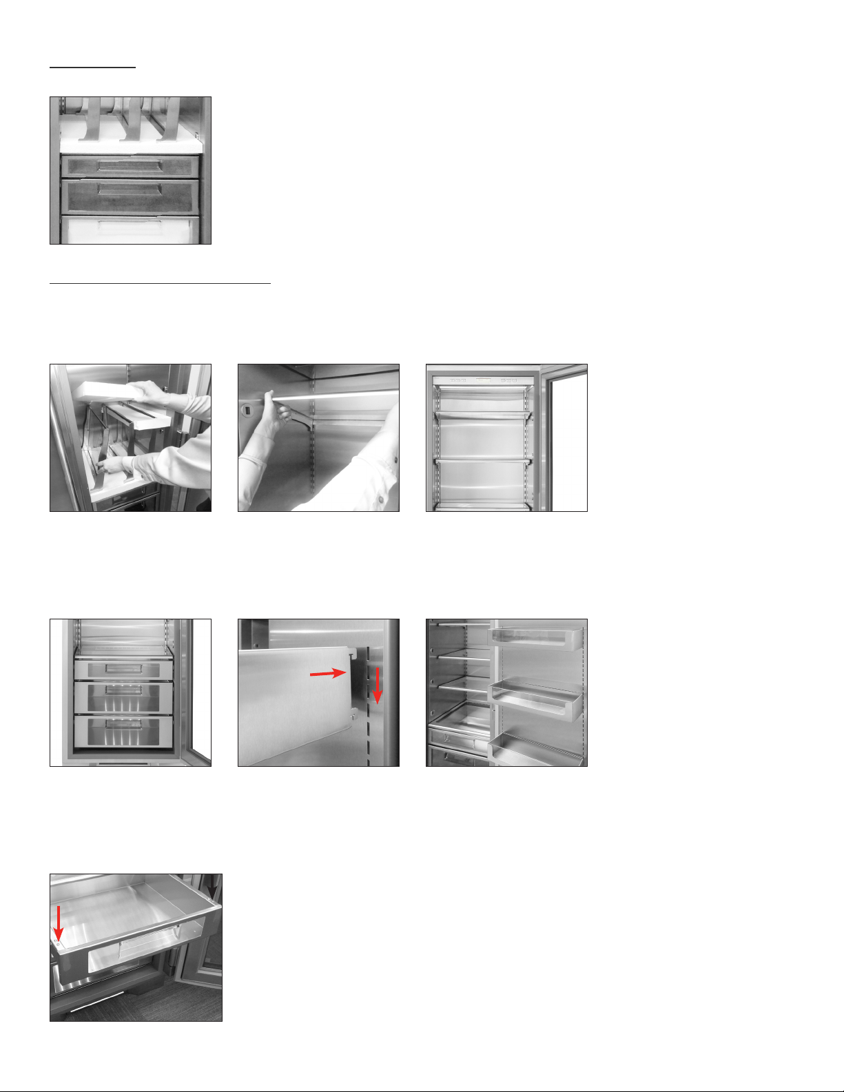
DOOR BINS
The door bins are located in the bottom drawer of the refrigerator. To install, push tabs into the slots in the door
and slide downward unit it stops. To remove or adjust a door bin, lift up and away from door back.
NOTE: BE CAUTIOUS OF PLACING TALL ITEMS IN TOP DOOR BIN, AS ITEMS MIGHT INTERFERE
WITH UI CONTROL PANEL.
REFRIGERATOR STORAGE
GLASS SHELVES
Remove the top foam piece holding the glass shelves. Carefully remove shelves and set aside. Remove all other
packing material. To install, insert glass shelf into the shelf standards on the back wall, with the front tilted
upward, and then lower the front until it stops. To remove or adjust a glass shelf, tilt up, and then lift up and out.
All shelving and door bins come packaged inside the unit.
FINAL GLASS SHELF INSTALLATION
FINAL DOOR BIN INSTALLATION
SHELVING
DRAWERS
To remove a drawer, pull drawer forward until it stops. Use a Phillips screw driver to remove the two (2) screws
securing the drawer to the slides, then lift the drawer up and out of unit. To reinstall, pull drawer slides all the
way forward on unit, and then slide the drawer onto the slides until the hook on the back of the slide is over top
of the drawer, reinstall the screws using the Phillips screw driver.
TEC_TM_009 Rev. B
December 31, 2019 Page 45 of 50
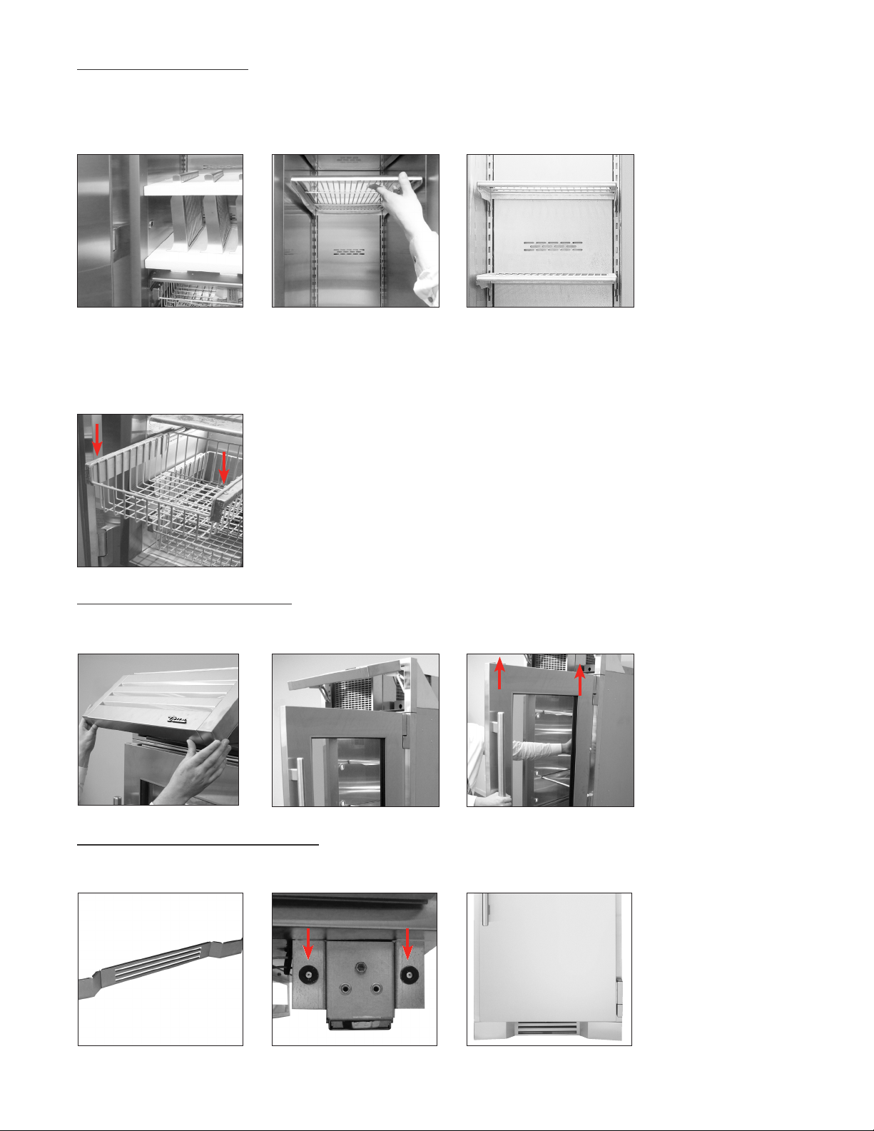
FREEZER STORAGE
WIRE SHELVES
Remove the top foam piece holding the wire shelves. Carefully remove shelves and set aside. Remove all other
packing material. To install, insert wire shelf into the shelf standards on the back wall, with the front tilted upward,
and then lower the front until it stops. To remove or adjust a wire shelf, tilt up, and then lift up and out.
WIRE BASKETS
To remove a basket, pull drawer forward until it stops. Use a Phillips screw driver to remove the two (2) screws
securing the basket to the slides, then lift the basket up and out of unit. To reinstall, pull drawer slides all the way
forward on unit, and then slide the basket onto the slides until the hook on the back of the slide is over top of the
rails, reinstall the screws using the Phillips screw driver.
REMOVING THE DOORS
Open the top louver grill. With the door open at 90 degrees, lift the door straight up and out of the hinges.
To re-install, hold the door 90 degrees to the opening and align hinge posts to the hinges. Lower the door into place.
KICK PLATE INSTALLATION
The kick plate is shipped with the unit but not attached to allow access to level the unit. Once the unit is level,
the kick plate attaches to the front, bottom of the unit with magnets located on the left and right.
KICK PLATE MAGNETSKICK PLATE INSTALLED KICK PLATE
FINAL WIRE SHELF INSTALLATION

TRUE RESIDENTIAL
®
TEC_TM_009 Rev. B
December 31, 2019 Page 46 of 50

TEC_TM_009 Rev. B
December 31, 2019 Page 47 of 50
s t a i n l e s s s t e e l e q u i p m e n t c a r e a n D c l e a n i n g
g e n e r a l m a i n t e n a n c e
c O n D e n s a t i O n
D a t a t a g
c O n t a c t u s
w a r r a n t y s t a t e m e n t
47 - 50
PRESERVE THE MOMENT
®

TRUE RESIDENTIAL
®
TEC_TM_009 Rev. B
December 31, 2019 Page 48 of 50
CAUTION: DO NOT USE ANY STEEL WOOL,
ABRASIVE OR CHLORINE BASED PRODUCTS TO
CLEAN STAINLESS STEEL SURFACES.
STAINLESS STEEL OPPONENTS
There are three basic things which can break down
your stainless steel’s passivity layer and allow
corrosion to rear its ugly head.
1. Scratches from wire brushes, scrapers, and steel
pads are just a few examples of items that can be
abrasive to stainless steel’s surface.
2. Deposits left on your stainless steel can leave
spots. You may have hard or soft water depending
on what part of the country you live in. Hard
water can leave spots. Hard water that is heated
can leave deposits if left to sit too long. These
deposits can cause the passive layer to break
down and rust your stainless steel.
All deposits left from food prep or service should
be removed as soon as possible.
3. Chlorides are present in table salt, food, and
water. Household and industrial cleaners are the
worst type of chlorides to use.
STAINLESS STEEL CLEANING AND RESTORATION
Do not use stainless steel cleaners or similar solvents to
clean plastic or powder-coated parts. Instead, use warm
soapy water.
• For routine cleaning and removal of grease and oil,
apply white vinegar, ammonia, or any good commercial
detergent* with a soft cloth or sponge.
• Stainless steel polish (e.g., Zep
®
Stainless Steel Polish,
Weiman
®
Stainless Steel Cleaner & Polish, Nyco
®
Stainless Steel Cleaner & Polish, or Ecolab
®
Ecoshine
®
)
and olive oil can act as a barrier against fingerprints and
smears.
• Degreasers* (e.g., Easy-Off
®
Specialty Kitchen Degreaser
or Simple Green
®
Industrial Cleaner & Degreaser) are
excellent for removal of grease, fatty acids, blood and
burnt-on foods on all surfaces.
STAINLESS STEEL EQUIPMENT CARE AND CLEANING
• For restoration/passivation or removing stubborn stains
and discoloration, Brillo
®
Cameo
®
, Zud
®
Cleanser,
Ecolab
®
Specifax™ First Impression
®
Metal Polish, Sheila
Shine, or talc can be applied by rubbing in the direction
of the polish lines.
*Do not use detergents or degreasers with chlorides or phosphates.
NOTE: The use of proprietary names is intended for example
only and does not constitute or imply an endorsement.
Omission of proprietary cleansers from this list does not
imply inadequacy.
8 TIPS TO HELP PREVENT RUST ON STAINLESS STEEL
MAINTAIN THE CLEANLINESS OF YOUR EQUIPMENT
Avoid build-up of hard stains by cleaning frequently.
Use cleaners at the recommended strength (alkaline
chlorinated or non-chloride).
USE THE CORRECT CLEANING TOOLS
Use non-abrasive tools when cleaning your stainless
steel products. The stainless steel’s passive layer will
not be harmed by soft cloths and plastic scouring
pads.
CLEAN ALONG POLISHING LINES
Polishing lines ("grain") are visible on some stainless
steels. Always scrub parallel to polishing lines when
visible. Use a plastic scouring pad or soft cloth when
you cannot see the grain.
USE ALKALINE, ALKALINE-CHLORINATED OR
NON-CHLORIDE CLEANERS
While many traditional cleaners are loaded with
chlorides, the industry is providing an ever increasing
choice of non-chloride cleaners. If you are not sure
of your cleaner’s chloride content, contact your
cleaner supplier. If they tell you that your present
cleaner contains chlorides, ask if they have an
alternative. Avoid cleaners containing quaternary
salts, as they can attack stainless steel, causing
pitting and rusting.
TEC_TM_009 Rev. B
December 31, 2019 Page 49 of 50
RINSE
When using chlorinated cleaners, you must rinse and
wipe dry immediately. It is better to wipe standing
cleaning agents and water as soon as possible. Allow
the stainless steel equipment to air dry. Oxygen helps
maintain the passivity film on stainless steel.
NEVER USE HYDROCHLORIC ACID (MURIATIC ACID) ON
STAINLESS STEEL
Even diluted, hydrochloric acid can cause corrosion,
pitting and stress corrosion cracking of stainless
steel.
WATER TREATMENT
To reduce deposits, soften hard water when possible.
Installation of certain filters can remove corrosive and
distasteful elements. Salts in a properly maintained
water softener can also be to your advantage. Contact
a treatment specialist if you are not sure of the
proper water treatment.
REGULARLY RESTORE & PASSIVATE STAINLESS STEEL
Stainless steel gets its stainless properties from
the protective chromium oxides on its surface.
If these oxides are removed by scouring, or by
reaction with harmful chemicals, then the iron in
the steel is exposed and can begin to oxidize, or
rust. Passivation is a chemical process that removes
free iron and other contaminants from the surface
of stainless steel, allowing the protective chromium
oxides to re-form.
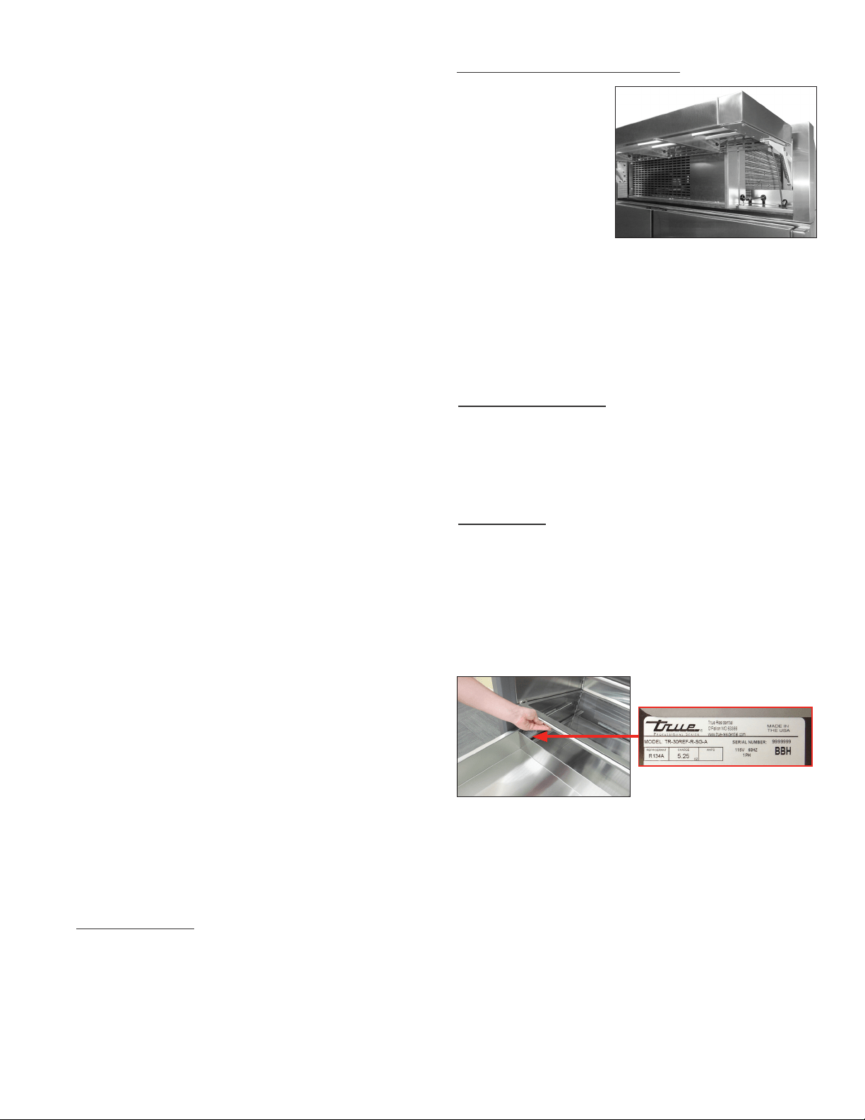
GENERAL MAINTENANCE
Keeping the
condenser coil clean
will minimize required
service and lower
electrical cost. The
condenser coil is
accessible from the
front. The condenser
coil should be cleaned by removing dust and other
build-up from the tube assembly with vacuum or a
cleaning rag. When properly cleaned you should be
able to see through the tube assembly. Warranty does
not cover cleaning the condenser coil.
CONDENSATION
Leaving the door open for a long period of time or
a unit that is running with little to no product inside
may also cause excessive condensation.
DATA TAG
Please have your model number and seven-digit serial
number on hand so we can better assist you with your
service- or parts-related inquiries. These numbers
are on the data tag, located on the left hand side wall
by the pull out wire basket in freezers, and the upper
drawer in refrigerators.
CONTACT US
CUSTOMER SERVICE
Phone: 888-616-8783
www.true-residential.com
WARRANTY DEPARTMENT
Phone: 844-849-6179
trueresidentialwarranty@truemfg.com
SERVICE DEPARTMENT
Phone: 844-746-9423
service@truemfg.com

TRUE RESIDENTIAL
®
TEC_TM_009 Rev. B
December 31, 2019 Page 50 of 50
LIMITED 30 DAY COSMETIC WARRANTY
Stainless steel doors, handles, and shelves are warranted to be free from defective materials or workmanship for a period of thirty (30)
days from the date of original retail purchase. Any defects must be reported to the selling dealer within thirty (30) days from the date of
original retail purchase. This limited warranty excludes any type of freight / concealed damage.
THREE-YEAR PARTS & LABOR WARRANTY *For units purchased after Feb 1, 2013.
TRUE warrants to the original purchaser of every new TRUE refrigerated unit, the cabinet and all parts thereof, to be free from defects in
material or workmanship under normal and proper use and maintenance as specified by TRUE and upon proper installation and start-up
in accordance with the instruction packet supplied with each TRUE unit. TRUE’s obligation under this warranty is limited to a period of
three (3) years from the date of original installation or thirty nine (39) months after shipment date from TRUE, whichever occurs first.
SIX-YEAR SEALED SYSTEM WARRANTY - PARTS & LABOR *For units purchased after Feb 1, 2013.
TRUE warrants its hermetically sealed system: compressor, evaporator coil, condenser coil, drier, metering device and connecting tubing
to be free from defects in both material and workmanship under normal and proper use and maintenance service for a period of six (6)
years from the date of original installation but not to exceed six (6) years and three (3) months after shipment from the manufacturer,
whichever occurs first.
SEVEN THROUGH TWELVE-YEAR SEALED SYSTEM WARRANTY - PARTS ONLY *For units shipped from True after Feb 1, 2017
and REGISTERED via True’s Product Registration Page – TRUE warrants its hermetically sealed system: compressor, evaporator coil,
condenser coil, drier, metering device and connecting tubing to be free from defects in both material and workmanship under normal
and proper use and maintenance service period of Twelve (12) years from the date of original installation but not to exceed twelve (12)
years and three (3) months after shipment from the manufacturer, whichever occurs first. Product must be registered with True to qualify
for this warranty. Factory seconds and clear Ice machines are excluded from this warranty.
TERMS APPLICABLE TO EACH WARRANTY
Any part covered under the above warranties that is determined by TRUE to have been defective within the time frame is limited to the
repair or replacement, including labor charges, of defective parts or assemblies. The labor warranty shall include standard straight time
labor charges only and reasonable travel time, as determined by TRUE.
WARRANTY CLAIMS
All claims for labor or parts must be made directly through TRUE. All claims should include: model number and serial number of
cabinet, proof of purchase, and date of installation. In case of warranted compressor, the compressor model tag must be returned to
TRUE along with the above listed information.
WHAT IS NOT COVERED BY THIS WARRANTY
TRUE’s sole obligation under this warranty is limited to either repair or replacement of parts, subject to the additional limitations below.
This warranty neither assumes nor authorizes any person to assume obligations other than those expressly covered by this warranty.
NO CONSEQUENTIAL DAMAGES. TRUE is not responsible for economic loss, profit loss; or special, indirect or consequential
damages, including without limitation, losses or damages arising from food or product spoilage claims whether or not on account or
refrigeration failure.
WARRANTY IS NOT TRANSFERABLE. This warranty is not assignable and applies only in favor of the original purchaser/user to whom
delivered. Any such assignment or transfer shall void the warranties herein made and shall void all warranties, express or implied,
including any warranty or merchantability or fitness for a particular purpose.
IMPROPER USAGE. TRUE assumes no liability for parts or labor coverage for component failure or other damages resulting from
improper usage or installation or failure to clean and/or maintain product as set forth in the warranty packet provided with the unit.
ALTERATION OR NEGLECT. TRUE is not responsible for the repair or replacement of any parts that TRUE determines have been
subjected after the date of manufacture to alteration, neglect, abuse, misuse, accident, damage during transit or installation, fire, flood,
or act of God.
IMPROPER ELECTRICAL CONNECTIONS. TRUE is not responsible for the repair or replacement of failed or damaged components
resulting from electrical power failure, high or low voltage, use of extension cords, or improper grounding of the unit.
YOUR RIGHTS UNDER STATE LAW.
This warranty gives you specific legal rights and you may have other rights that vary from state to state. Some states do not allow
the exclusion or limitation of consequential damages or a limitation on how long an implied warranty lasts, so the above exclusion or
limitation may not apply to you.
OUTSIDE U.S./CANADA. This warranty does not apply to, and TRUE is not responsible for, any warranty claims made on products sold
or used outside the United States or Canada.
SUBMIT WARRANTY CLAIMS TO: True Residential
2001 East Terra Lane
O’Fallon MO 63366
TRUE RESIDENTIAL
®
SERIES
LIMITED WARRANTY STATEMENT
MS • 5/17 • API2335

TEC_TM_009 Rev. B December 27, 2019 Page 49 of 50

CONTACT US
www.true-resident ial.com
toll free (888)616-8783
TP · MISC_2248 · 6.19
212530
December 27, 2019Page 50 of 50 TEC_TM_009 Rev. B