Loading ...
Loading ...
Loading ...
32
17
10
11
Qty - 5
14
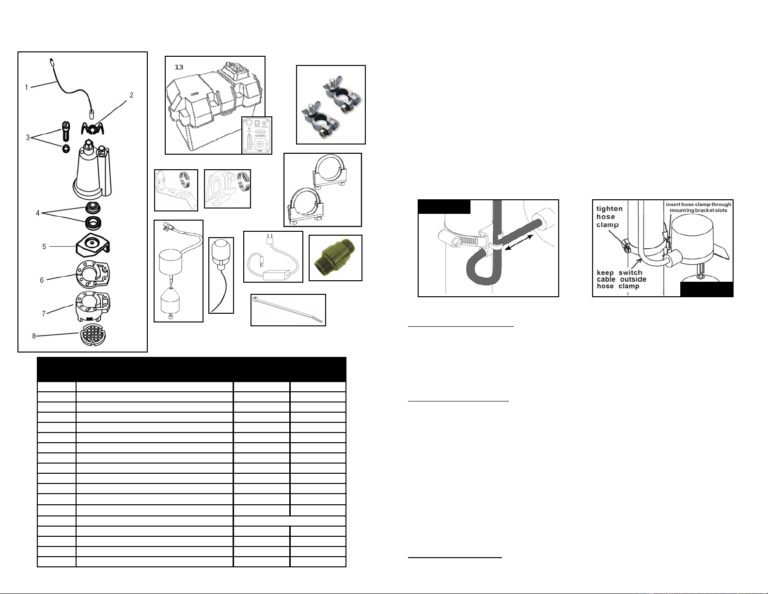
Ref Descripción
PIEZAS PARA EL MODELO
92370
92372
1 Cable de alimentación 99158 99158
2 Asa 99051 99051
3 Tapón de llenado de aceite con junta tórica 99056 99056
4 Sello de eje 99057 99057
5 Impulsor 99065 99065
6 Junta 99088 99088
7 Voluta y base 99098 99098
8
Rejilla de entrada
99059
99059
9 Interruptor de flotador 92050 92055
10
Abrazadera para interruptor de flotador con amarre
99180
n/a
11 Soporte para interruptor de flotador vertical n/a 99185
12 Conjunto de perno en U y abrazadera de silla 99462 99462
13 Caja para batería (unidad completa) 99464 99464
14 Ataduras para cable
15
Tablero de control
99465
99465
16 Cable de alimentación de CA 99467 99467
17 Terminales de batería (+ y - ) 99460 99460
18 Válvula de paso 99505 99505
Compre localmente
LISTA DE PIEZAS
Para ordenar piezas de repuesto, llame al 1-800-495-9278
15
13
18
16
9
9
12
5
9. Thread the check valve (C) onto the discharge of the back-up pump
10. Plumb the back-up pump to the primary pump piping using a 1-1/2” Female Adapter (D),
45° Street Elbow (E) and a Wye fitting (F). It is highly recommended to do a “dry fit”
before permanently gluing the pipe and fittings together. Place the assembly in the basin
to make sure that it fits and that the primary float switch operates freely before
permanently gluing the pipe and fittings together.
11. Remove the assembly from the basin and glue all fittings.
12. Next, secure the float switch to the discharge pipe using the provided clamp. See figure 2
below for proper installation. DO NOT fully tighten the clamp at this time. Leave it a bit
loose so you can adjust the position of the float in the next steps.
13. After the float switch has been attached to the discharge pipe, place the entire assembly
in the basin. Make sure the primary pump float switch will operate freely and not contact
the sides of the basin. Connect the pump assembly to the discharge pipe. Use either a
flexible coupling with clamps or a solvent weld PVC or ABS coupling.
Tethered Switch Installation
Adjust the tether length of the float switch so the back up pump will turn on when the water
level rises above the start level of the primary pump. Make sure the “on” level does not exceed
the top of the basin. It is recommended to keep at least a 2” clearance from the top of the
basin. Position the float so that it will operate freely and not contact the sides of the basin or
the primary pump. Once positioned properly, completely tighten the float switch clamp.
Vertical Switch Installation
Position the Vertical Float Switch on the discharge pipe so it will turn on when the water level
rises above the start level of the primary pump. Make sure the “on” level does not exceed the
top of the basin. It is recommended to keep at least a 2” clearance from the top of the basin.
You can adjust the “off” level of the vertical float by moving the grommet up or down on the
vertical float rod. Once positioned properly, completely tighten the float switch clamp.
NOTE: There are many different options for assembling this unit. The instructions above
represent one of the most common installations. Your installation may vary. If you have a very
shallow basin, mounting the back-up pump above the primary pump may not be feasible. You
may also position the pump on bottom of the basin. Make sure the back up pump is positioned
so that it won’t interfere with the primary pump operation. If you have any questions about your
particular installation, please feel free to contact us at 1-800-495-9278 or at
www.superiorpumpco.com
TETHERED SWITCH INSTALLATION VERTICAL SWITCH INSTALLATION
Adjust tether
length to desired
activation level
FIGURE 2
FIGURE 2
Loading ...
Loading ...
Loading ...