AstroAI WH5000A True RMS Digital Multimeter
Product's Documents
Below are documents related to this product, you can read online or download:
- User Manual - (English) Read Online | Download pdf
NOTE: Fully read and understand this manual before using this Digital Multimeter.
WARNING: To avoid possible electric shock or personal injury, and to avoid possible damage to the Meter or to the equipment being tested, adhere to the following rules:
● Before using the Meter, inspect the exterior casing. Do not use the Meter if it is damaged or if all or part of the exterior casing is removed. Look for cracks or missing plastic. Pay special attention to the insulation around the connectors.
● Inspect the test leads for damaged insulation or exposed metal. Check the test leads for continuity.
● Do not apply more than the rated voltage, as marked on the Meter, between the terminals or between any terminal and grounding.
● The manual rotary switch should be placed in the correct position before measurement and should NOT be moved during measurement to prevent damage to the Meter.
● When the Meter is working at an effective voltage over 60V in DC or 30V rms in AC, special care should be taken because there is a danger of electric shock.
● Use the proper terminals, function, and range for your measurements.
● Do not use or store the Meter in a high-temperature environment, do not expose to high levels of humidity, or near strong magnetic fields. The performance of the Meter may deteriorate after dampening.
● When using the test leads, keep your fingers behind the finger guards.
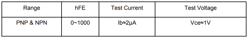
● Disconnect circuit power and discharge all high-voltage capacitors before testing resistance, continuity, diodes or hFE.
● Replace the battery as soon as the battery indicator appears. With a low battery, the Meter might produce false readings that can lead to electric shock and personal injury.
● Remove the connection between the testing leads and the circuit being tested, and turn the Meter power off before opening the Meter case.
● When servicing the Meter, use only the same model number or identical electrical specifications replacement parts.
● The internal circuit of the Meter shall not be altered at will to avoid damage of the Meter and any accident.
● Clean using a soft cloth and mild detergent for the surface of the Meter. Do not use abrasive materials or solvents to prevent the surface of the Meter from corrosion and damage.
● Turn the Meter off when not in use and take out the battery when it is not going to be used for an extended period of time. Regularly check the battery as it may leak when it has not been used for some time. Replace the battery as soon as leaking appears. A leaking battery will damage the Meter.
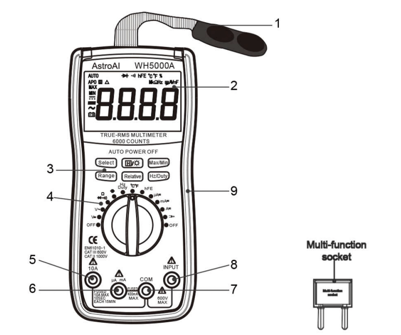
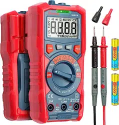
1. Magnetic Hanger
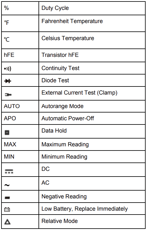
2. LCD Screen
3. Function Buttons
4. Rotary Function Switch
5. 10A Terminal
6. μA/mA Terminal
7. COM Terminal
8. INPUT Terminal
9. Silicone Sleeve
10. Multi-Function Socke
When using the rotary switch to select a multimeter function, use the Select Button to further select the function. This applies only to multifunction settings like the temperature and test functions.
 Button
Hold and backlight function button. When taking a measurement, press this button to hold the data for easier recording. Press the button again to remove the hold function.
Press and hold this button to turn on the backlight on the LCD screen.
Max/Min Button
When taking a measurement, press this button once to enter “Max Mode”. In this mode, the multimeter will capture the highest reading it records. Press this button again to enter “Min Mode” which will capture the lowest reading it records.
Press and hold this button to exit the Max/Min Modes.
Range Button
AC/DC Voltage, AC Current, and Resistance can all be measured in both Auto and Manual ranging. The multimeter will come set to Auto, but if you desire to select the range manually, press the Range Button repeatedly to find the desired range. Beware of selecting a range too low, as it will Overload the device and the multimeter will not give a reading.
Press and hold the Range Button to return back to Auto Ranging.
Relative Button
When taking measurements, you can utilize the Relative Button to get more accurate readings by removing the resistance of the test leads, for example. To activate this function, simply press the Relative Button. A small triangle (delta symbol) will appear on the display and the reading should change to zero.
Press the Relative Button again to exit relative mode.
Hz/Duty Button
When using the Hz/Duty Cycle function on the multimeter, quickly switch between functions by pressing this button. You can also switch to measuring Hz while measuring other functions, like Voltage, for example, by pressing this button during measurement.
Clamp Meter Attachment (Not Included)
Use a clamp meter attachment to measure currents, use the COM terminal for the black lead from the clamp meter and the Input terminal for the red lead from the clamp meter.
Multi-Function Socket (Included)
Use the multi-function socket to measure both Capacitors and Transistors. Be sure to correctly insert the multi-function socket into the COM and INPUT plugs with negative the negative terminal on the multi-function socket on the left side and the positive on the right side.
Accuracy is guarantied for 1 year 23°C±5°C less than 80%RH
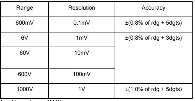
Input Impedance: 10MΩ
Overload Protection: 600V DC/AC RMS
Max. Input voltage: 600V DC
Measure DCV 1000V under CATII
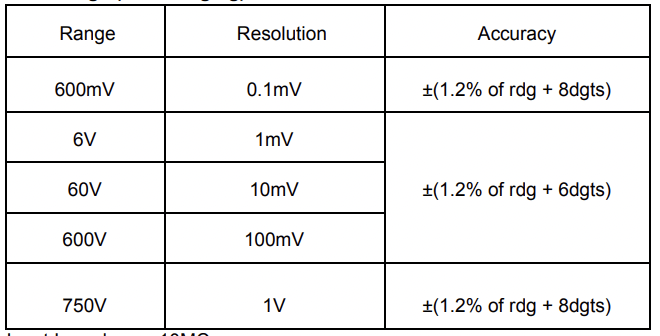
Input Impedance: 10MΩ
Frequency Range: 40Hz ~ 400Hz
Overload Protection: 600V DC/AC rms
Measure AC V 750V under CATII CAT III
Max. Input voltage: 600V AC RMS CATIII
Overload Protection: F0.4A/600V Fuse
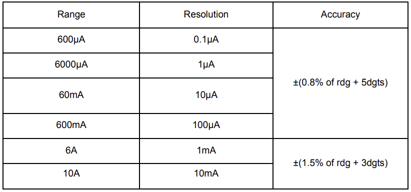
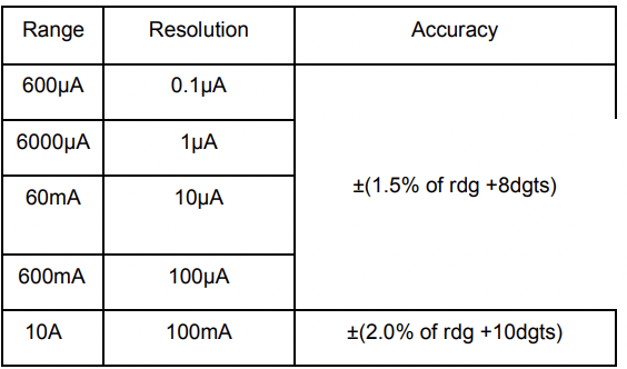
Overload Protection:
● “mA” Jack: F0.4A/600V fuse
● “10A” Jack: F10A/600V fuse Max.
Input Current:
● “mA” jack: 600mA
● “10A” jack: 10A (For measurements >5A: Duration 15 minutes)
Voltage Drop:
● 600µA, 60mA: 60mV,
● 6000µA, 600mA and 10A ranges: 600mV
Overload Protection:
● “mA” jack: F0.4A/600V fuse
● “10A” jack: F10A/600V fuse Max.
Input Current:
● “mA” jack: 400mA
● “10A” jack: 10A (For measurements>5A: duration15 minutes)
Voltage Drop:
● 600µA, 60mA ranges: 60mV
● 6000µA, 600mA and 10A ranges: 600mV
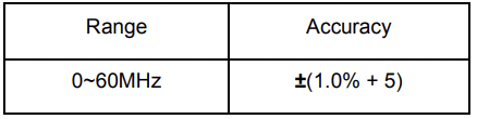
Frequency Range: 40Hz ~ 400Hz
 Open Circuit Voltage: about 0.25V
Overload Protection: 250V DC/AC RMS
| Range | Introduction | Remark |
 | The approximate forward voltage drop will be displayed | Open circuit voltage: about 1.5V |
 | The built-in buzzer will sound if the resistance is less than about 30Ω. | Open circuit voltage: about 0.5V |
Overload Protection: 250V DC/AC rms
For continuity test: When the resistance is between 30Ω and 70Ω, the buzzer may sound or may not sound. When the resistance is more than 70Ω, the buzzer will not sound
Overload Protection: F0.4A/600V fuse
Open circuit voltage: about 0.5V
Overload Protection: 250V DC/AC RMS
 or V
or V range. Choose either Auto or Manual range using the “Range” Button.
Note:
a. When measuring small ranges, the multimeter’s display will sometimes show an unstable result if the test leads are not connected to the load being measured. This is normal and will not affect measurements.
b. In manual range, when the multimeter shows “OL” or Over Range, you must select a higher range in order to get results.
c. To avoid damage to the meter, do not measure voltage exceeding 600V DC or 600V AC CATIII.
a. There is no option to change between manual and automatic ranges for current measurements.
4. Connect the test leads to the source or load to be measured.
5. Read LCD display. The polarity of the red test lead will be indicated.
 ” range.
Note:
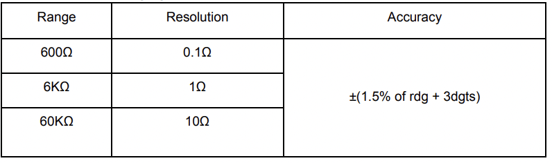
a. For resistance measurements >1MΩ, the meter may take a few seconds to stabilize reading. This is normal for high-resistance measurement.
b. When the input is not connected, i.e. at open circuit, the symbol “OL” will be displayed as an over range indicator.
c. Before measuring in-circuit resistance, be sure that the circuit under test has all power removed and all capacitors are fully discharged.
” range. ” range. ” will appear on the display.
a. In this case, simply switch the test leads from the anode to the cathode and vice versa.
 ” range.
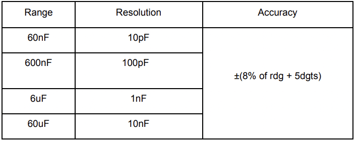
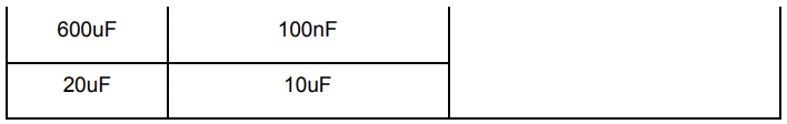
a. Connect the black test lead to the “COM” jack and the red test lead to the "INPUT” jack.
b. Set the function switch to “” range.
c. Connect the test leads to the capacitor to be measured. Be sure to be aware of the polarity of the connection.
Note:
a. When the capacitance under measure is more than 600uF, it needs at least 10 seconds to make readings stable.
Note:
a. Do not apply more than 250V RMS to the input.
 ” range.
Note:
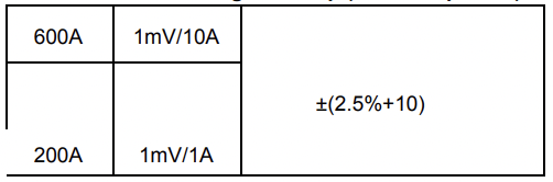
a. Each time a measurement is taken, make sure that only one cable is clamped and is in the center of the clamp jaws.
b. The clamp can only test for up to 600A, do not test circuits higher than 600A.
c. Do not touch the circuit with hand or skin.
d. The multimeter assumes a clamp has a sensitivity of 1A/1mV. The indicated value is the same as the measured value for clamps with 1A/1mV.
i. If you use a clamp whose sensitivity does not equal 1mV/1A, multiply the present reading by a factor which is determined by the used clamp, the result is the measured value. To determine the factor, please refer to the instructions of the clamp which you use.
The meter will power off after approximately 15 minutes of inactivity. To turn it on again, turn the rotary function switch, or press the “Select” or “Range” button for more than 2 seconds.
If the “  ” symbol appears on the display, the battery should be replaced immediately. Remove the rubber sleeve and the screws on the back of the multimeter to replace the battery.
Replace with NEDA 1604, 6F22, or equivalent 9V battery. Disconnect the test leads before opening the back of the multimeter.
Fuses will rarely need replacement and are normally only blown due to operator error. To replace the fuses, open the battery cover by removing the rubber sleeve as well as the screws on the back of the multimeter. Disconnect the test leads before opening the back of the multimeter.
Replace the damaged fuse with a new one with the same ratings. This meter uses two fuses:
Fuse1: 400mA, 600V, FAST, Min. Interrupt Rating 20000A, Ø10X38mm
Fuse 2: 10A, 600V, FAST, Min. Interrupt Rating 20000A, Ø10X38mm
Reference file: AstroAI WH5000A True RMS Digital Multimeter
Additionally, the document applies to other AstroAI models: ASIMT5000A-JP1