USER MANUAL
DT132A
DIGITAL MULTIMETER

CATALOG
INTRODUCTION
WARNING
INCLUDED IN BOX
DIAGRAM
DIMENSIONS
ELECTRICAL SYMBOLS
FUNCTION BUTTONS
PREPARATION
OPERATING INSTRUCTIONS
MAINTENANCE
TROUBLESHOOTING
SPECIFICATIONS
DETAILED SPECIFICATIONS
RECYCLING
WARRANTY PERIOD
03
04
06
06
07
07
08
09
10
15
16
18
18
22
22

Thank you for purchasing the AstroAI True RMS 4000 Counts Digital
Multimeter.
The AstroAI True RMS 4000 Digital Multimeter is designed to be safely
and accurately used by professionals in a commercial setting or DIYers
who need a little more utility from their standard digital multimeter.
This manual provides all safety information, operation instruction,
specifications, and maintenance information for the meter. This instru-
ment performs AC/DC Current, AC/DC Voltage, Resistance, Diode,
Capacitance, Continuity, Frequency, Duty Cycle, and Temperature mea-
surements.
Thank you again for choosing AstroAI, if you have any questions or
concerns regarding your product, please contact us via
INTRODUCTION
- 03 -
!
If you have any questions or concerns when using this prod-
uct,please feel free to contact our customer support or refer
to the detailed user manual on the product page.

WARNING
Before using the meter, inspect its exterior casing. Do not use the
meter if it is damaged or if any part of its exterior casing is
removed. Look for cracks or missing plastic. Pay special attention
to the insulation around the connectors.
Inspect the test leads for damaged insulation or exposed metal.
Check the test leads for continuity.
Do not apply more than the rated voltage, as marked on the meter,
between the terminals or between any terminal and grounding.
The manual rotary switch should be placed in the correct position
before measurement and should NOT be moved during measure-
ment. Failure to do so may damage the meter.
When the meter is working at an eective voltage over 60 V in DC or
30 V RMS in AC, exercise extra caution, there is an increased risk of
electric shock.
Always use the proper terminals, functions, and ranges for your
measurements.
Do not use or store the meter in a high-temperature environment,
near strong magnetic fields, or in high levels of humidity. The
meter’s performance may deteriorate after exposure to moisture.
To avoid possible electric shock, personal injury, meter damage,
and damage to the equipment being tested, always adhere to the
following rules:
- 04 -

When using the test leads, always keep your fingers behind the
finger guards.
Disconnect circuit power and discharge all high-voltage capacitors
before testing resistance, continuity, or diodes.
Replace the battery as soon as the low battery symbol appears.
With a low battery, the meter may produce false readings that can
lead to electric shock and personal injury.
Before opening the meter’s case, turn the meter o and disconnect
the testing leads from the circuit being tested.
When servicing the meter, only use replacement parts with the
same model number or identical electrical specifications as the
original.
Do not alter the meter’s internal circuitry, doing so may damage the
meter and cause personal injury.
Clean the meter’s exterior using a soft cloth and mild cleaner. To
prevent unnecessary corrosion and damage, do not clean with
abrasive materials or solvents.
Turn the meter o when not in use and remove the battery when it
is not going to be used for an extended period. Regularly check the
battery as it may leak when it has not been used for some time.
Replace the battery as soon as leaking appears. A leaking battery
will damage the meter.
- 05 -
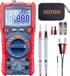
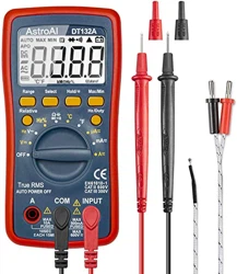
INCLUDED IN BOX
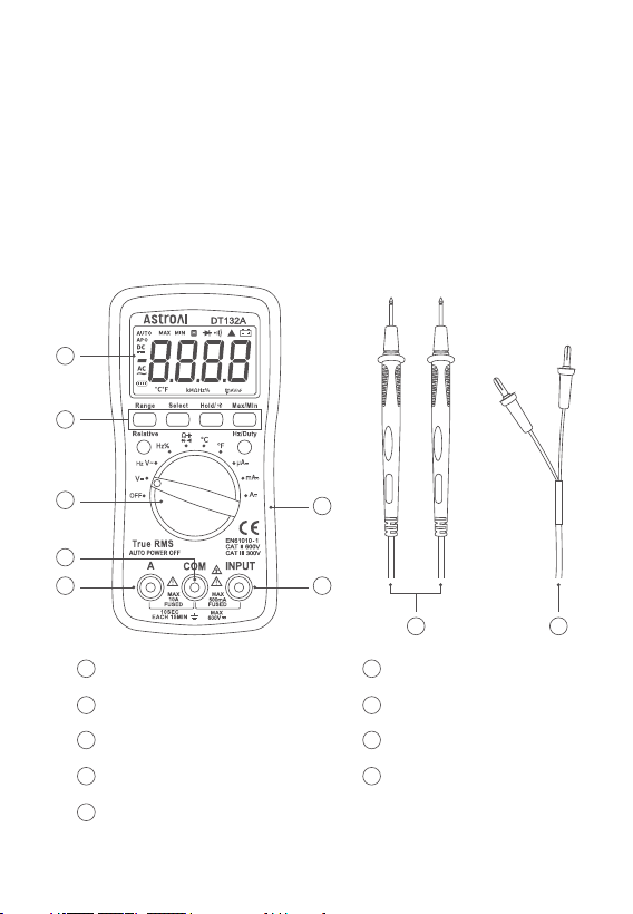
DIAGRAM
User Manual
Pair of Test Leads
LCD Screen
Function Buttons
Rotary Switch
COM Jack
A Jack
Rubber Sleeve
INPUT Jack
Test Leads
K-Type Thermocouple
×1
×1
×1
×1
K-Type Thermocouple
AstroAI 4000 Counts Multimeter
1
2
3
4
6
7
8
9
5
- 06 -
1
2
3
5 7
8
4
6
9
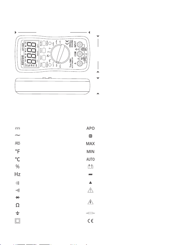
DIMENSIONS
ELECTRICAL SYMBOLS
6.2 in (158 mm)
3 in (76 mm)
1.4 in (35 mm)
DC (Direct Current) Automatic Power-O
Data Hold
Maximum Reading
Minimum Reading
Auto-Range Mode
Low Battery
Negative Reading
Relative Mode
Warning
AC (Alternating Current)
AC and DC
Fahrenheit Temperature
Celsius Temperature
Duty Cycle
Frequency
Capacitance
Continuity Test
Diode Test
Resistance
Dangerous Voltage may be
present
- 07 -
Fuse
Complies with EU Directives
Earth Ground
Double Insulated

FUNCTION BUTTONS
Select Button
When using the rotary switch to select a multimeter function, use the
Select Button to select a more specific function.
Hold/Backlight Button
When taking a measurement, press this button to hold the data for
easier recording. Press the button again to remove the hold function.
Press and hold this button to turn on the LCD screen’s backlight.
Press and hold the button again to turn o the backlight.
Range Button
AC/DC Voltage, AC/DC Current, and Resistance can all be measured
in both Auto and Manual ranging. The multimeter will ship set to
Auto. But if you desire to manually select the range, press the Range
Button repeatedly to find the desired range. Beware of selecting a
range too low, as it will overload the device and the multimeter will
not display a reading. Press and hold the Range Button to return to
Auto Ranging.
Max/Min Button
When taking a measurement, press this button once to enter “Max
Mode”. In this mode, the multimeter will capture the highest reading
it records. Press this button again to enter “Min Mode” which will
capture the lowest reading it records.
Press and hold this button to exit the Max/Min Modes.
- 08 -

PREPARATION
Relative Button
When taking measurements, you can utilize the Relative Button to
get more accurate readings by removing the resistance of the test
leads. To activate this function, simply press the Relative Button. A
small triangle (delta symbol) will appear on the display and the
reading should change to zero. Press the Relative Button again to
exit Relative Mode.
Hz/Duty Button
When using the Hz/Duty function on the multimeter, press this
button to quickly switch functions. You can also switch to measuring
the Hz/Duty cycle during AC voltage measurement.
1. Connect the test leads: Insert the red test lead into the “Input”
Jack and the black test lead into the “COM” Jack.
2. Turn the rotary switch to the “ ” setting and choose the “Select”
Button. Then, choose Continuity Mode. The “ ” symbol will
display on the screen.
3. Touch the red and black test leads together to check whether they
are functioning normally. The meter will beep harshly if the leads
are functioning normally.
- 09 -

OPERATING INSTRUCTIONS
Voltage Measurement
Current Measurement
a. During DC voltage measurement, use the “ ” symbol on the
screen to judge the polarity of the red test lead connection. If the
“ ” symbol is absent, that means the red test lead is connected
with positive polarity.
b. To avoid damaging the meter, do not measure voltages exceeding
600 V DC or 600 V AC.
c. Press the Hz/Duty Button to switch to Frequency or Duty cycle
when testing the AC voltage.
1. Connect the test leads: Insert the red test lead into the “Input”
Jack and the black test lead into the “COM” Jack.
2. Choose functions: Turn the rotary switch to the “V ” or “V ”
settings according to the measured voltage.
3. Connect the circuit: Connect one end of the test leads to the circuit
that needs to be measured, in parallel with the circuit.
4. Reading: Record the reading from the LCD screen. After measure-
ment, turn the rotary switch to the “OFF” position to turn o the meter.
1. Connect the test leads: Insert the black test lead into the “COM”
Jack. If the current is less than 500 mA, insert the red test lead
into the “INPUT” Jack; if the current ranges from 500 mA to 10 A,
insert the red test lead into the “A” Jack.
Note:
- 10 -

Resistance Measurement
1. Connect the test leads: Insert the red test lead into the “Input”
Jack and the black test lead into the “COM” Jack.
2. Choose functions: Turn the rotary switch to the “ ” setting and
press the “Select” Button to choose the resistance mode.
2. Choose functions: Turn the rotary switch to the “µA ” , “mA ” , or
“A ” settings according to the estimated value.
3. Choose current types: Press the “Select” Button to test the DC
current test value or the AC current test value.
4. Connect the circuit: Connect the test lead to the source lead or
load to be measured, in series with the circuit.
5. Reading: Record the reading from the LCD screen. After measure-
ment, turn the rotary switch to the “OFF” position to turn o the
meter.
a. DO NOT test currents exceeding 10 A AC/DC.
b. When performing DC current measurements, determine the
polarity of the red lead connection based on the presence or
absence of the “ ” symbol display. If the “ ” symbol is absent,
that means the red test lead is connected with positive polarity.
c. When testing a high current, for safety reasons, each measure-
ment time should be less than 10 seconds. The interval time
between tests should be greater than 15 minutes.
d. When testing the current, there must be a load in the circuit. DO
NOT connect the multimeter in series with the circuit unless there
is a load to measure. Connecting in series without a load may
damage the meter.
Note:
- 11 -

3.Connect the load: Place the test leads at both ends of the resistor
to be measured.
4. Reading: Record the reading from the LCD screen. After measure-
ment, turn the rotary switch to the “OFF” position to turn o the meter.
Continuity Test
1. Connect the test leads: Insert the red test lead into the “Input”
Jack and the black test lead into the “COM” Jack.
2. Turn the rotary switch to the “ ” setting and choose the “Select”
Button. Then, choose Continuity Mode. The “ ” symbol will display
on the screen.
3. Connect the load: Place the test leads at both ends of the load to
be measured.
a. If the resistance test value exceeds 1 MΩ, the meter may take a
few seconds to stabilize the reading. This is normal for high-resis-
tance testing.
b. Do not change the resistor while taking a measurement. Doing so
may damage the meter and aect the test results.
c. Do not test parallel circuits. The accuracy of the measurements
will be aected, and the results may not be accurate.
d. Do not directly measure the internal resistance of micrometers,
galvanometers, batteries, and other such instruments.
e. In the event of disconnection, the “OL” symbol will display on the
screen.
f. Before testing the internal resistance of the circuit, please ensure
that all power sources are removed from the tested circuit and all
capacitors are fully discharged.
Note:
- 12 -

4. Reading: If the circuit load is less than 30 Ω, the buzzer will buzz. If
it exceeds 30 Ω, the LCD screen will display the load reading. After
measurement, turn the rotary switch to the “OFF” position to turn
o the meter.
Diode Test
1. Connect the test leads: Insert the red test lead into the “INPUT”
Jack and the black test lead into the “COM” Jack.
2. Choose functions: Turn the rotary switch to the “ ” setting and
press the “Select” Button to choose the Diode Mode. The “ ”
symbol will display on the screen.
3. Connect the diode: Connect the red test lead to the positive end of
the diode and the black test lead to the negative end.
4. Reading: The meter will display the approximate value of the posi-
tive voltage. If the leads are incorrectly connected to the diode
electrodes, the LCD will display “OL” . The solution is to switch the
test leads’ position. After measurement, turn the rotary switch to
the “OFF” position to turn o the meter.
Capacitance Measurement
1. Connect the test leads: Insert the red test lead into the “INPUT”
Jack and the black test lead into the “COM” Jack.
2. Choose functions: Turn the rotary switch to the “ ” setting and
press the “Select” Button. Then, choose the Capacitance function.
3. Connect Capacitance: Connect to the capacitor that is to be measured.
4. Reading: Record the reading from the LCD screen. After measure-
ment, turn the rotary switch to the “OFF” position to turn o the meter.
- 13 -

Temperature Measurement
1. Insert the negative (black) plug of the K-type thermocouple into
the “COM” Jack and the positive (red) plug into the “INPUT” Jack.
2. Choose functions: Turn the rotary switch to the “ºC” or “ºF” setting.
3. Method: Carefully use the end of the K-Type thermocouple to touch
the object being measured.
4. Reading: Record the stable result from the LCD screen. After mea-
surement, turn the rotary switch to the “OFF” position to turn o
the meter.
Frequency Measurement
1. Connect the test leads: Insert the red test lead into the “INPUT”
Jack and the black test lead into the “COM” Jack.
2. Press the “Hz/Duty” Button to switch to frequency measurement
or duty cycle measurement.
3. Connect the signal source: Connect the test leads to the two ends
of the circuit to be measured.
4. Reading: Record the reading from the LCD screen. After measure-
ment, turn the rotary switch to the “OFF” position to turn o the meter.
- 14 -

MAINTENANCE
If the “ ” symbol appears on the display, the battery should be
replaced immediately.
Battery Replacement
1. Turn o the power and remove the test leads plugged into the meter.
2. Unscrew the screw and remove the kickstand to replace the battery.
3. Remove the old batteries and replace them with new batteries of
the same specification (size AAA, 1.5 V × 3).
4. Put the kickstand in place and fasten it with the removed screw.
Fuses will rarely need replacement and are normally only blown due
to operator error.
Fuse Replacement
1. Turn o the power and remove the test leads plugged into the meter.
2. Remove the rubber sleeve of the multimeter and unscrew the 6
screws. Then, remove the back cover to replace the fuse.
3. Remove the blown fuses and replace them with new fuses of the
same specification.
4. Put the back cover in its original position and secure it with screws.
Always replace a damaged fuse with a new one of the same rating.
This meter uses two fuses:
Fuse 1: 500 mA/600 V, Ø5 × 20 mm
Fuse 2: 10 A/600 V, Ø5 × 20 mm
Note:
- 15 -

TROUBLESHOOTING
How to Find a Live Wire in a Socket
1. Switch to the Voltage Test setting.
2. Connect the black test lead to the grounded wire or jack. Connect
the red test lead to one of the jacks to be measured.
3. Check both jacks. One should have a reading and the other should
remain at or near zero. The live wire will have the reading.
Automotive Parasitic Battery Drain
1. Check if the battery voltage and power generation are within the
normal range. The battery voltage is generally around 12.7 V and
the power generation is around 14 V.
2. Turn o all electrical accessories inside and outside the car and
close the doors.
3. Remove the negative electrode of the battery. Set the multimeter
to the maximum current level and connect the meter in series to
the battery.
4. Connect the red test lead to the negative line and the black test
lead to the battery terminal.
5. If necessary, adjust the meter to a lower range.
6. Wait for about 30 minutes; after all the modules of the vehicle enter
their sleep state, read the accurate static discharge current. The
discharge current is generally 0.02 A (20 mA). However, this can vary
depending on the vehicle. Generally, it is normal to not exceed 50 mA.
7. If the drain is larger than 50 mA, begin checking fuses individually
for which circuit is carrying the excess load.
- 16 -

Is the Diode Functioning Correctly?
If the red test lead is connected to the positive pole of the diode and
the black lead is connected to the negative, then the diode should be
in a forward conduction state. The displayed value is the forward
voltage drop.
Normal Diode Forward Pressure Drop
The general silicon tube is 0.5-0.7 V while the germanium tube is
0.15 - 0.3 V.
Polarity Judgment Method
8. If a removed fuse reduces the battery draw to below 50 mA, it can
be determined the corresponding circuit is drawing the excess
discharge.
1. Switch the multimeter to the Resistance setting.
2. Connect the two test leads to the diode’s two electrodes.
3. Measure one result, then swap the positions of the test leads.
Then, measure the second result.
4. The larger result is the reverse resistance and the smaller result
is the forward resistance. The smaller resistance is when the
black test lead is connected to the positive end of the diode and
the red lead is connected to the negative end.
- 17 -

Digital Display
Sampling Speed
LCD Size
Range Selection
Polarity Indication
Overload Indication
Low Battery Indication
Operating Environment
Storage Temperature
Power
Dimensions
Weight
3 ¾, 3999
2 Times Per Second
2.17 x 1.22 in (55 x 31 mm)
Auto or Manual
“-” Displayed
“OL” Displayed
Yes
32~104 °F (0~40 °C); <80% RH
14~122 °F (-10~50 °C); <85% RH
3 x 1.5 V, AAA Battery
5.71 x 2.76 x 1.38 in (145 x 70 x 35 mm)
Approximately 0.49Ib (223g)
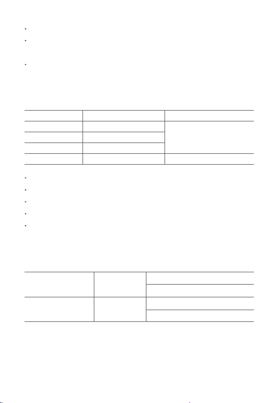
SPECIFICATIONS
DETAILED SPECIFICATIONS
Accuracy is guaranteed for 1 year when stored at 73±9 °F
(23 ± 5 °C).
DC Voltage (Auto-Ranging)
400 mV
4 V
40 V
400 V
0.1 mV
1 mV
± (0.8% + 3)
± (1.0% + 5)
± (0.8% + 5)
10 mV
100 mV
600 V 1 V
AccuracyRange Resolution
- 18 -
AC Voltage (Auto-Ranging)
400 mV
4 V
40 V
400 V
1 mV
1 mV
± (1.0% + 8)
± (1.2% + 5)
± (1.2% + 5)
10 mV
100 mV
600 V 1 V
AccuracyRange Resolution
Temperature
-40~1370 °C
-40~2000 °F
1 °C
-40~302 °F: ± (2.5% + 4)
302~2000 °F: ± (2.5% + 4)
-40~150 °C: ± (2.5% + 4)
150 ~1370 °C: ± (2.5% + 4)
1 °F
AccuracyRange Resolution
Input Impedance: 10 MΩ
Overload Protection: 600 V DC or 600 V AC RMS
(200 mV Range: 250 V DC/AC RMS)
Max Input Voltage: 600 V DC
Input Impedance: 10 MΩ
Frequency Range: 40 Hz ~ 400 Hz
Overload Protection: 600 V DC or 600 V AC RMS
Response: Average, calibrated in RMS of sine wave
Max Input Voltage: 600 V AC RMS
Note: Dierent temperature sensors are configured in dierent
temperature test ranges. Normal temperature sensors are provided
for standard configuration.
- 19 -
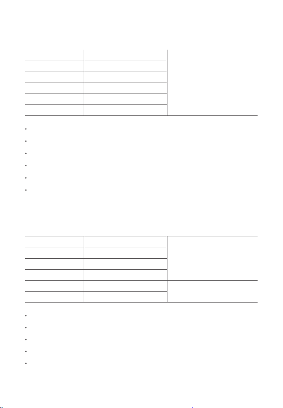
DC Current
400 µA
4000 µA
40 mA
400 mA
0.1 µA
1 µA
± (1.2% + 8)
10 µA
100 µA
4 A 1 mA
AccuracyRange Resolution
10 A 10 mA
Overload Protection: µA and mA Ranges: F0.5 A/600 V fuse
4 A and 10 A Ranges: F10 A/600 V fuse
Max Input Current: “INPUT” Jack: 200 mA
“A” Jack: 10 A
Voltage Drop: 400 µA, 40 mA, and 4 A Ranges: 40 mV
4000 µA, 400 mA, and 10 A ranges: 400 mV
AC Current
400 µA
4000 µA
40 mA
400 mA
0.1 µA
1 µA
± (1.5% + 8)
± (2.0% +10)
10 µA
100 µA
4 A 1 mA
AccuracyRange Resolution
10 A 10 mA
Overload Protection: µA and mA Ranges: F0.5 A/600 V fuse
4 A and 10 A Ranges: F10 A/600 V fuse
Max Input Current: “INPUT” Jack: 200 mA
“A” Jack: 10 A
Voltage Drop: 400 µA, 40 mA, and 4 A Ranges: 40 mV
- 20 -
Resistance (Auto-Ranging)
400 Ω
4 kΩ
40 kΩ
400 kΩ
0.1 Ω
1 Ω
± (1.5% + 3)
10 Ω
100 Ω
4 MΩ 1 kΩ
AccuracyRange Resolution
40 MΩ 10 kΩ
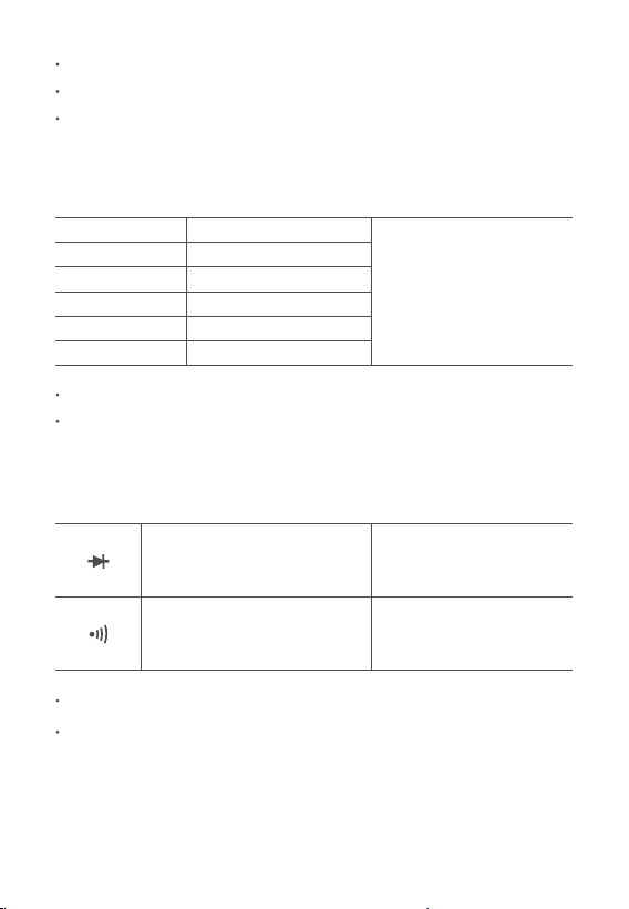
Diode and Continuity
NoteRange Description
Open Circuit Voltage: 0.25 V
Overload Protection: 250 V DC/AC RMS
Overload Protection: 250 V DC/AC RMS
For continuity test: When the resistance is between 50 Ω and 100
Ω, the buzzer may or may not sound. When the resistance is more
than 100 Ω, the buzzer will not sound.
4000 µA, 400 mA, and 10 A Ranges: 400 mV
Frequency Range: 40 Hz ~ 400 Hz
Response: Average, calibrated in RMS of sine wave
The approximate
forward voltage drop will
be displayed.
Open circuit voltage:
About 3 V
Open circuit voltage:
About 1 V
The built-in buzzer will
sound if the resistance is
less than about 30 Ω.
- 21 -

RECYCLING
You may dispose of the product when its service life has ended, please
recycle the recyclable parts according to local guidelines.
WARRANTY PERIOD
3-Year Limited Warranty from AstroAI.
Each AstroAI True RMS 4000 Counts Digital Multimeter will be free
from defects in material and workmanship. This warranty does not
cover fuses, disposable batteries, and damage from neglect, misuse,
contamination, alteration, accident, or abnormal conditions of operation or
handling, including overvoltage failures caused by use outside the
multimeter’s specified rating, or normal wear and tear of mechanical
components. This warranty covers the original purchaser only and is
not transferable.
If this product is defective, please contact AstroAI Customer Support at
support@astroai.com.
Capacitance
40 nF
400 nF
4 uF
40 uF
10 pF
100 pF
± (5% + 5)
± (8% + 10)
1 nF
10 nF
100 uF ~ 2 mF 100 nF
AccuracyRange Resolution
Frequency
5/50/500/5 K; 50 K/500 K/5 MHz
± (1.0%+ 3)
AccuracyRange
- 22 -

Web: www.astroai.com
E-Mail: support@astroai.com