Loading ...
Loading ...
Loading ...
KBF / KBF-UL + KMF (E6) 04/2020 page 141/163
Chamber size
115
240
720
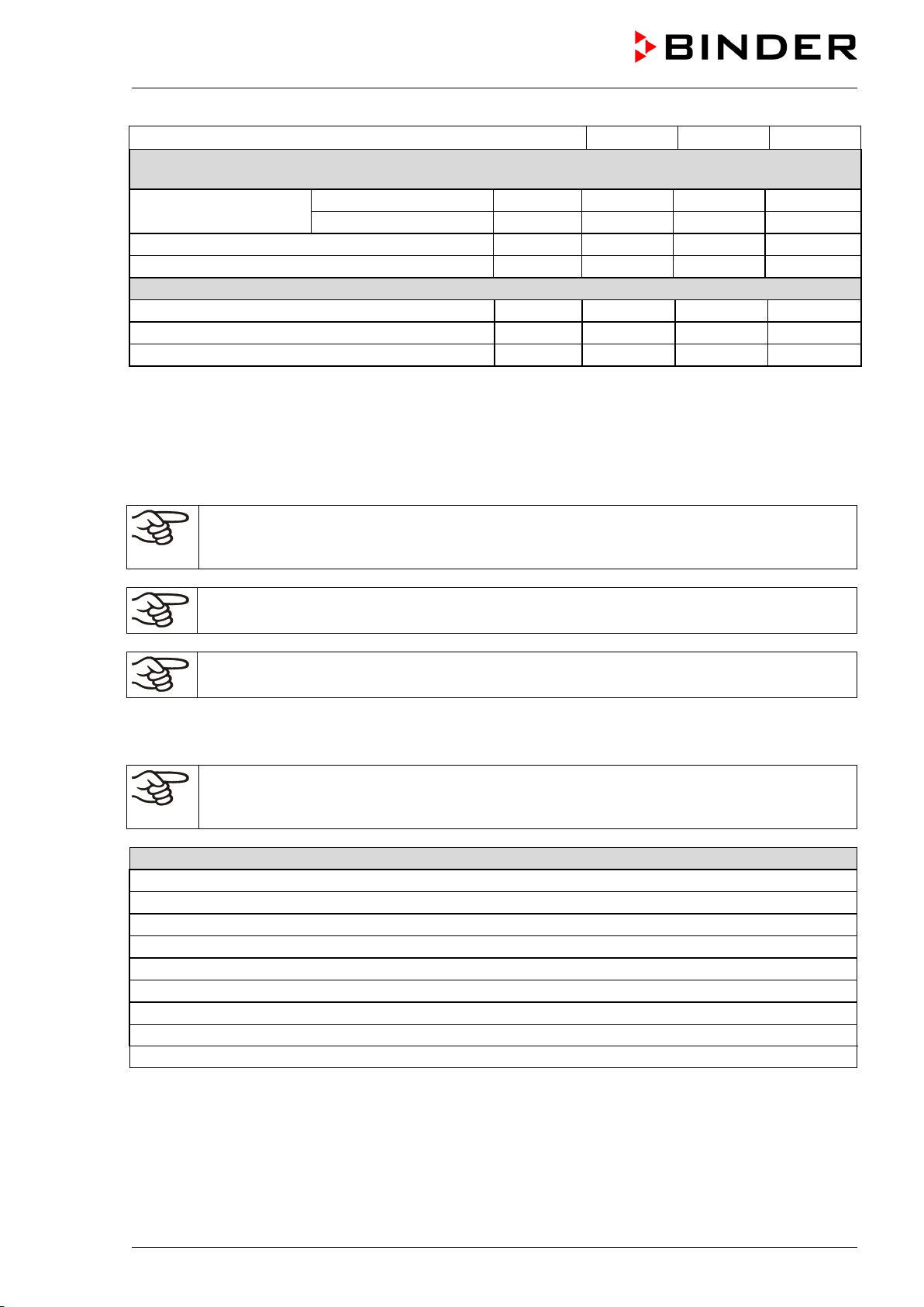
Deviant electrical data KMF for the USA and Canada
(model versions KMF115-240V, KMF240-240V, KMF720-240V)
Nominal voltage (+/-10%)
at 50 Hz power frequency
V
200-240
200-240
200-240
at 60 Hz power frequency
V
200-240
200-240
200-240
Current type
2~
2~
2~
Power plug
NEMA
6-20P
6-20P
6-20P
Environment-specific data
Noise level (mean value)
dB (A)
52
52
56
Energy consumption at 85 °C / 185 °F and 85 % r.h.
Wh/h
570
570
900
Filling weight of refrigerant R 134A (GWP 1300)
kg
0.180
0.240
0.430
*) Depending on the set-point.
All technical data is specified for unloaded chambers with standard equipment at an ambient temperature
of +22 °C +/- 3°C / 71.6 °F +/- 5.4 °F and a power supply voltage fluctuation of +/-10%. Technical data is
determined in accordance to BINDER Factory Standard Part 2:2015 and DIN 12880:2007.
All indications are average values, typical for chambers produced in series. We reserve the right
to change technical specifications at any time.
Refrigerating performance decreases while operating the chamber at temperatures < 0 °C /
32 °F due to icing of the evaporators. For this reason defrost the chamber regularly, e.g. once
a week.
If the chamber is fully loaded, the specified heating up and cooling down times may vary ac-
cording to the load.
Bringing a source of humidity into the inner chamber will affect the minimum humidity specifi-
cation and may affect the humidity accuracy.
23.6 Equipment and options (extract)
To operate the chamber, use only original BINDER accessories or accessories / components
from third-party suppliers authorized by BINDER. The user is responsible for any risk arising
from using unauthorized accessories.
Regular equipment
Microprocessor display program controller with 2-channel technology for temperature and humidity
Ethernet interface for computer communication
Temperature safety device class 3.1 acc. to DIN 12880:2007
Inner glass door with gasket
DCT™ refrigerating system with refrigerant R134a
Microprocessor controlled humidifying and dehumidifying system *) (humidity range, see diagram)
Sizes 240, 720 and 1020: Four castors (2 lockable)
1 rack (KMF), 2 racks (KBF / KBF-UL), stainless steel
Access port 30 mm with silicone plug
*) A water supply (1 to 10 bar) is necessary for the installation of the humidifying and de-humidifying
system (chap. 4.3). If no suitable house water connection is available, you can manually supply water
by filling a freshwater can (option, chap. 19.9). Furthermore, a water drain in a max. distance of 3 me-
ters / 9.8 ft. and a max. height of 1 meter / 3.3 ft. is required (chap. 4.2).
Loading ...
Loading ...
Loading ...