Loading ...
Loading ...
Loading ...
4 Chef 540 Upright Cooker
installation
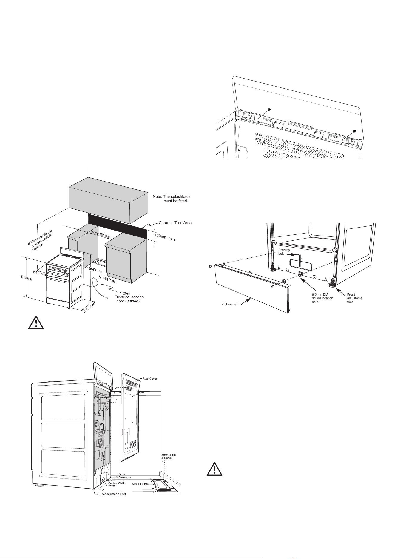
Location
The appliance has been designed to fit a 550mm gap in kitchen
cabinetry or have free space on either side. Ensure the top of the
hotplate is at least 10mm higher than the level of the benchtop.
Electric hob models must not be installed in a corner; they must be
installed at least 100mm from the side wall.
Gas hob models must be installed with a minimum clearance of
100mm to side walls made of unprotected combustible material.
For gas models, refer to section 6.10.1 in AS/NZS 5601.1 for
all relevant clearance.
WARNING
warning
In order to avoid accidental tipping of the appliance (for
example, by a child climbing onto the open oven door), the
anti tilt plate and stabilising bolt MUST be installed.
Position anti-tilt plate to the rear wall and 25mm from side of
cupboard. Securely fix anti-tilt plate to the floor with fasteners.
Adjust levelling feet on cooker as required.
Clearance to side wall
(refer notes above)
Splashback must be fitted to the rear using the two screws
used to fasten the anti-tilt plate and splashback on the rear of
the product.
Stabilising bolt
Kick-panel
Front
adjustable
feet
6.5mm DIA
drilled location
hole.
Stability
bolt
1. Remove oven door - to be done by qualified personnel only.
(Refer to procedure).
2. Remove screws from kick panel. To remove kick panel lift
kick panel upwards to release the two Location Tabs from
the holes in the bottom of the panel.
3. Position cooker into the ant-tilt plate and then mark the
position for the Stability Bolt hole on the floor.
4. Pull cooker out and drill the bolt hole, using a 6.5mm
masonry or wood drill. Minimum 30mm deep for concrete.
5. Reposition cooker back into place and fit the Stability
Bolt through the slot and into the drilled hole.
6. If the cooker is placed on a base, measures must be
taken to prevent the appliance slipping from the base.
7. Carefully remove any protective plastic film to prevent
damage to the appliance.
WARNING
warning
For your safety this cooker is designed to be moved out of
position by a qualified person only.
The unit must be pushed up against the wall on installation.
On gas units check that the gas hose, if used, has not been
kinked during installation.
Loading ...
Loading ...
Loading ...