Loading ...
Loading ...
Loading ...
10 Chef 540 Upright Cooker
Operation on SNG
• If the cooker is to be used with SNG, then the grill burner
MUST be modified by the replacement of the shutter,
which fits into the throat of the grill burner
• A conversion kit can be obtained by contacting the
Customer Care Centre
Restraining Device
Anchor Points
Connection
Gas
Point
150mm
650m m
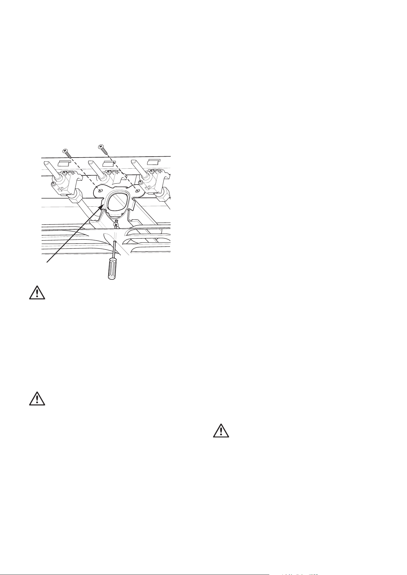
Grill shutter
(Default shutter for NG use)
WARNING
warning
1. Disconnect electric power before removing control panel.
2. Pull off control knobs and remove control panel.
3. Remove the existing NG shutter securing screw (refer to
diagram above) and slide upwards to disengage from
grill burner.
4. Slide the SNG shutter into position and secure with screws.
5. Re-fit the control panel and control knobs. Be careful to not
trap any wires. Re-connect to electrical power
Testing the gas cooker
WARNING
warning
You MUST test the cooker after installation, before you hand
it over to the customer.
You MUST have a manometer and a connecting tube.
Checking the gas supply
1. Check the manometer zero point is correct.
2. Connect the manometer to the cooker pressure test point.
This is located on the regulator or LPG inlet fitting.
3. Turn on the gas supply and the electricity (if applicable)
and try to ignite the gas. Note: It will take additional time
to light the gas for the first time, as air needs to be purged
from the pipes.
4. Check the operating pressure for the particular gas type
(see 'Gas Type' table).
• For LPG cookers: Adjust the regulator if necessary
(this may be remote from the cooker).
installation
• For Natural Gas cookers: Regulators are supplied pre-
adjusted and configured by the component maker for use
with Natural Gas. The appliance installer is not required
to make an adjustment to obtain the correct outlet pressure
setting. An arrow on the base of the regulator indicates
the direction of the gas flow when the inlet and outlet
of the regulator are orientated correctly.
5. When the regulator has been fitted check for leaks from
the connections with soapy water.
Checking regulator function
With the appliance operating, check the outlet pressure:
1. When all the burners of the appliance are operating
at maximum.
2. When the smallest burner of the appliance is operating
at minimum, Under these conditions the outlet pressure
should not vary from nominal operating pressure of 1.0kPa
by more then ± 20% (ie ±0.20kPa for Natural Gas).
If the regulator appears to not be performing satisfactorily
then check the following points:
1. If the outlet pressure is consistently too low then.
• the inlet pressure may be too low and adjustment
of an upstream regulator may be needed, or
• an upstream regulator or valve with insufficient flow
capacity may be present in the gas supply line. It may be
necessary to repeat the checks whilst measuring both the
inlet and outlet pressure to determine if the inlet pressure
is in the range 1.13-5kPa.
2. Check that the regulator has been fitted to the gas supply
line in the correct orientation.
3. Replace the regulator if it fails to perform after the checks.
Testing cooker features
• Observe the flame appearance on each burner. If it is
smaller or larger than expected, then the injector size
needs checking
• If the flame is unsatisfactory, then refer to the Electrolux
Technical Publications and correct the fault if possible
• When maximum flame appearance is correct, check the turn
down setting on each burner. If incorrect, proceed as follows:
WARNING
warning
1. Disconnect electric power.
2. Remove the control panel and adjust the bypass screw
mounted on the body of each hotplate control cock.
3. Check the ignition on all burners both separately and
in combination.
4. Check the operation of the electrical components,
if applicable.
5. When operating correctly, show customer how to use
the cooker.
6. If not operating correctly, advise the customer to ring
Electrolux service. Place a warning sign on cooker or
if dangerous, disconnect cooker.
Loading ...
Loading ...
Loading ...