Loading ...
Loading ...
Loading ...
1
2
3
4
5
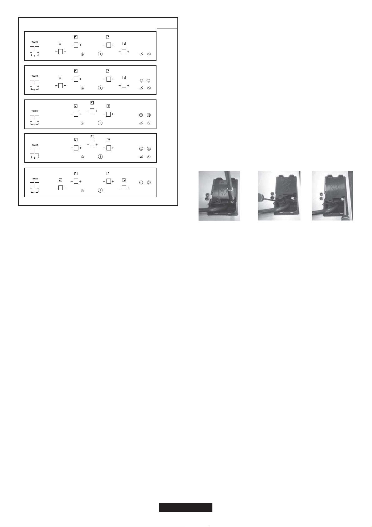
LAYOUT
According to model
1. ON/OFF
2."+"
3."-"
4. TIMER
5.Additional cooking zone led
6. Cooking zone programming indicator
7. Bridge
8. Child lock
9. Melting
10. Boiling
"Installation must conform to the standards & directives."
Manufacturer declines all responsibility for any damage
that might be caused by unsuitable or unreasonable use.
WARNING: Manufacturer cannot be held responsible for
any incident or its consequences that may arise during the
use of an appliance not linked to the earth, or linked to an
earth whose continuity is defective.
Before any electrical operation, please check the supply
tension shown on the electricity meter, the adjustment of the
circuit- breaker, the continuity of the connection to earth to
the installation and that the fuse is suitable.
The electrical connection to the installation should be made
according to the rated power of the Appliance; this should
be made via an Omni pole cut-out switch.
If the appliance has a socket outlet, it must be installed so
that the socket outlet is accessible.
The yellow/green wire of the power supply cable must be
connected to the earth of both power supply and appliance
terminals.
For any questions regarding power supply cord refer to
After Sales Service or a qualified technician.
If the hob is fitted with power supply cord, this shall be
connected only to a power supply of 220-240 V between
phase and neutral.
It is however possible to connect the hob to:
Three Phase 220-240 V3
Three Phase 380-415 V2N
To proceed to the new connection, please follow below
instructions:
Before making the connection, make sure that the
installation is protected by a suitable fuse, and that it is
fitted with wires of a large enough section to supply the
appliance normally.
Turn over the hob, glass side against the working top,
taking care to protect the glass.
Open the cover in the following sequence:
231
- unscrew the cable clamp "1";
- find the two tabs located on the sides;
- put the blade of a flat screw-driver in front of each tab "2" e
"3", push in and press;
- remove the cover.
To release the power supply cord:
- Remove the screws retaining the terminal block which
contains the shunt bars and the conductors of the supply
cord;
- Pull out the supply cord.
Operations to be carried out to make a new connection:
- Choose the power supply cable in accordance with the
recommendations in the table;
- Pass the power supply cable into the clamp;
- Strip the end of each conductor of the supply cord on a 10
mm length, by taking in account the requested length of the
cord for the connection to the terminal block;
- According to the installation and with the help of shunt bars
which you should have recovered in the first operation, fix
the conductor as shown on the chart;
- Fix the cover;
- Screw the cable clamp.
Note: make sure the terminal board screws are tight.
Operations to be carried out to make a new connection:
- Choose the power supply cable in accordance with the
recommendations in the table;
- Pass the power supply cable into the clamp;
- Strip the end of each conductor of the supply cord on a 10
mm length, by taking in account the requested length of the
cord for the connection to the terminal block;
- According to the installation and with the help of shunt bars
07 GB- IE
8 8
8
8 8
8
8 8
8
8
8
8 8
8
8
8
8 8
8
8 8
8
8 8
8
8 8
8
2
22
23
33
3
4
5
55
5
55
7
7
6
1
8
910
4
4
4
4
23
23
23
23
23
23
23
23
23
23
23
2323
23
1
8
1
8
1
8
1
8
6
6
6
6
Loading ...
Loading ...
Loading ...