Loading ...
Loading ...
Loading ...
INSTALLATION INSTRUCTIONS
Models starting with “MH”
1. Follow Step 2 of installation instructions on removing liner
from outer shell.
2. The hood is provided with a preinstalled 3-prong cord to
provide power to the hood and blower.
• If an appropriate outlet is not accessible due to the
installation location, the power cord may be removed at the
liner’s junction box, and the hood may be direct wired to a
dedicated, standard non-GFCI 120V, 10A min circuit.
3. If installing a remote blower (HYEX or ATEX), the blower box
at the base of the duct cover and the transition piece may be
removed and discarded. A separate back-draft damper will
need to be added to the ductwork. The duct work will need to
extend fully into the top of the hood shell and connect to the
liner’s 10” dia. outlet collar. Ensure power cable from remote
blower is routed in space between duct cover and the exhaust
duct, and additional length is provided at the base to allow
connection to the hood’s harness.
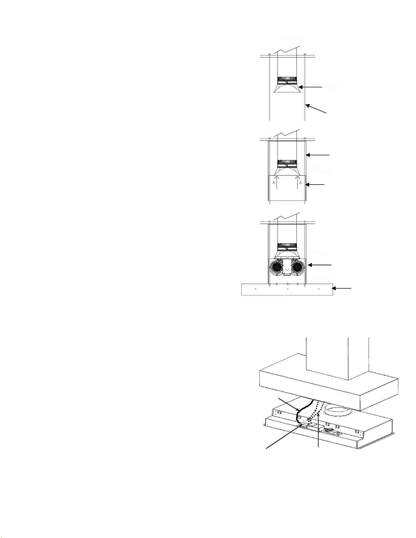
4. Four pieces of full-length, 3/8” dia. threaded rod (not
provided) are necessary to secure the hood shell and
associated duct cover to structural framing in the ceiling
above the hood shell. The threaded rod must pass through
the framing or blocking in the ceiling and be secured with a
washer and nut on either side to prevent the threaded rod
from moving up or down. The rod may be in multiple sections
to ease installation but must be appropriately coupled at the
joints between members. It should pass through the holes in
the duct cover at all 4 corners, then through the holes in the
hood shell, and secured with washers and nuts inside the
hood shell. Any excess length will need to be trimmed off to
avoid interference with the liner when it is reinstalled.
5. Ensure the lower hood shell is level, then anchor it to the wall.
Lag screws into the wall behind the hood are only needed in
the lower portion of the hood to keep it tight to the wall. Holes
are provided, but additional holes may be added to provide
alignment with structural framing members behind the
wallboard.
6. For in-hood blower(s):
a. Mount the blower(s) into duct cover / internal blower
box using hardware provided.
b. Plug the connector(s) from the liner’s harness into the
blower(s)
7. For remote blower, connect cable from blower to the 3-
position terminal on the liner’s harness. (See step 4.5)
8. Re-install liner using Step 5 from installation instructions.
Take care to route power cord and blower cables to avoid
pinching during liner reinstallation.
Duct cover
3/8” diameter
threaded rod
(4 pieces)
Internal blower box
(may be removed if
using a remote blower)
Transition
Lower
hood shell
In-Hood
Blower(s)
16
2. power cord
junction box
2. power cord
6b. Blower harness(es)
Loading ...
Loading ...
Loading ...