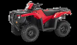
Honda 2020 Fourtrax Foreman Rubicon 4X4 Scooter

User Manual

For 2020 FOURTRAX FOREMAN RUBICON 4X4. Also, The document are for others Honda models: TRX520FA5 4×4, TRX520FA6 4×4 WITH POWER STEERING, TRX520FA7 4×4 DELUXE

PDF File Manual, 286 pages, Read Online | Download pdf file

2020 FOURTRAX FOREMAN RUBICON 4X4 photo
background
Contents
Contents
These pages give an overview of the contents of your owner’s
manual.
The first page of each section lists the topics covered in that section.
ATV Safety ..................................................................................1
Important safety information you should know, plus a look at the
safety related labels on your ATV.
Instruments & Controls ..............................................................9
The location and function of indicators and controls on your ATV
and operating instructions for various controls and features.
Before Riding ............................................................................61
The importance of wearing a helmet and other protective gear,
how to make sure you and your ATV are ready to ride, and
important information about loading.
Basic Operation & Riding .........................................................77
How to start and stop the engine, shift gears, and brake. Also,
riding precautions.
2020 Foreman Rubicon AT
(
TRX520FA5 4x4/FA6 4x4 w/Power Steering/FA7 4x4 Deluxe)
31HR6650
M
OM 17072 (1902)
Loading page 2...
Loading page 3...
Loading page 4...
Loading page 5...
Loading page 6...
Loading page 7...
Loading page 8...
Loading page 9...
Loading page 10...
Loading page 11...
Loading page 12...
Loading page 13...
Loading page 14...
Loading page 15...
Loading page 16...
Loading page 17...
Loading page 18...
Loading page 19...
Loading page 20...
Loading page 21...
Loading page 22...
Loading page 23...
Loading page 24...
Loading page 25...
Loading page 26...
Loading page 27...
Loading page 28...
Loading page 29...
Loading page 30...
Loading page 31...
Loading page 32...
Loading page 33...
Loading page 34...
Loading page 35...
Loading page 36...
Loading page 37...
Loading page 38...
Loading page 39...
Loading page 40...
Loading page 41...
Loading page 42...
Loading page 43...
Loading page 44...
Loading page 45...
Loading page 46...
Loading page 47...
Loading page 48...
Loading page 49...
Loading page 50...
Loading page 51...
Loading page 52...
Loading page 53...
Loading page 54...
Loading page 55...
Loading page 56...
Loading page 57...
Loading page 58...
Loading page 59...
Loading page 60...
Loading page 61...
Loading page 62...
Loading page 63...
Loading page 64...
Loading page 65...
Loading page 66...
Loading page 67...
Loading page 68...
Loading page 69...
Loading page 70...
Loading page 71...
Loading page 72...
Loading page 73...
Loading page 74...
Loading page 75...
Loading page 76...
Loading page 77...
Loading page 78...
Loading page 79...
Loading page 80...
Loading page 81...
Loading page 82...
Loading page 83...
Loading page 84...
Loading page 85...
Loading page 86...
Loading page 87...
Loading page 88...
Loading page 89...
Loading page 90...
Loading page 91...
Loading page 92...
Loading page 93...
Loading page 94...
Loading page 95...
Loading page 96...
Loading page 97...
Loading page 98...
Loading page 99...
Loading page 100...
Loading page 101...
Loading page 102...
Loading page 103...
Loading page 104...
Loading page 105...
Loading page 106...
Loading page 107...
Loading page 108...
Loading page 109...
Loading page 110...
Loading page 111...
Loading page 112...
Loading page 113...
Loading page 114...
Loading page 115...
Loading page 116...
Loading page 117...
Loading page 118...
Loading page 119...
Loading page 120...
Loading page 121...
Loading page 122...
Loading page 123...
Loading page 124...
Loading page 125...
Loading page 126...
Loading page 127...
Loading page 128...
Loading page 129...
Loading page 130...
Loading page 131...
Loading page 132...
Loading page 133...
Loading page 134...
Loading page 135...
Loading page 136...
Loading page 137...
Loading page 138...
Loading page 139...
Loading page 140...
Loading page 141...
Loading page 142...
Loading page 143...
Loading page 144...
Loading page 145...
Loading page 146...
Loading page 147...
Loading page 148...
Loading page 149...
Loading page 150...
Loading page 151...
Loading page 152...
Loading page 153...
Loading page 154...
Loading page 155...
Loading page 156...
Loading page 157...
Loading page 158...
Loading page 159...
Loading page 160...
Loading page 161...
Loading page 162...
Loading page 163...
Loading page 164...
Loading page 165...
Loading page 166...
Loading page 167...
Loading page 168...
Loading page 169...
Loading page 170...
Loading page 171...
Loading page 172...
Loading page 173...
Loading page 174...
Loading page 175...
Loading page 176...
Loading page 177...
Loading page 178...
Loading page 179...
Loading page 180...
Loading page 181...
Loading page 182...
Loading page 183...
Loading page 184...
Loading page 185...
Loading page 186...
Loading page 187...
Loading page 188...
Loading page 189...
Loading page 190...
Loading page 191...
Loading page 192...
Loading page 193...
Loading page 194...
Loading page 195...
Loading page 196...
Loading page 197...
Loading page 198...
Loading page 199...
Loading page 200...
Loading page 201...
Loading page 202...
Loading page 203...
Loading page 204...
Loading page 205...
Loading page 206...
Loading page 207...
Loading page 208...
Loading page 209...
Loading page 210...
Loading page 211...
Loading page 212...
Loading page 213...
Loading page 214...
Loading page 215...
Loading page 216...
Loading page 217...
Loading page 218...
Loading page 219...
Loading page 220...
Loading page 221...
Loading page 222...
Loading page 223...
Loading page 224...
Loading page 225...
Loading page 226...
Loading page 227...
Loading page 228...
Loading page 229...
Loading page 230...
Loading page 231...
Loading page 232...
Loading page 233...
Loading page 234...
Loading page 235...
Loading page 236...
Loading page 237...
Loading page 238...
Loading page 239...
Loading page 240...
Loading page 241...
Loading page 242...
Loading page 243...
Loading page 244...
Loading page 245...
Loading page 246...
Loading page 247...
Loading page 248...
Loading page 249...
Loading page 250...
Loading page 251...
Loading page 252...
Loading page 253...
Loading page 254...
Loading page 255...
Loading page 256...
Loading page 257...
Loading page 258...
Loading page 259...
Loading page 260...
Loading page 261...
Loading page 262...
Loading page 263...
Loading page 264...
Loading page 265...
Loading page 266...
Loading page 267...
Loading page 268...
Loading page 269...
Loading page 270...
Loading page 271...
Loading page 272...
Loading page 273...
Loading page 274...
Loading page 275...
Loading page 276...
Loading page 277...
Loading page 278...
Loading page 279...
Loading page 280...
Loading page 281...
Loading page 282...
Loading page 283...
Loading page 284...
Loading page 285...
Loading page 286...

User Manual - Transcript

  • Page 1 - English - : Contents Contents These pages give an overview of the contents of your owners manual The first page of each section lists the topics covered in that section ATV Safety 1 Important safety information you should know plus a look at the safety related labels on your ATV Instruments amp Controls 9 The location and function of indicators and controls on your ATV and operating instructions for various controls and features Before Riding 61 The importance of wearing a helmet and other protective gear how to make sure you and your ATV are ready to ride and important information about loading Basic Operation amp Riding 77 How to start and stop the engine shift gears and brake Also riding precautions 2020 Foreman Rubicon AT TRX520FA5 4x4FA6 4x4 wPower SteeringFA7 4x4 Deluxe 31HR6650 M OM 17072 1902
  • Page 2 - English - : Contents Contents Servicing Your Honda 117 Why your ATV needs regular maintenance what you need to know before servicing your Honda an owner maintenance schedule and instructions for specific maintenance and adjustment items Tips 205 How to store and transport your ATV and how to be an environmentally responsible rider Taking Care of the Unexpected 215 What to do if you have a flat tire your engine wont start etc Technical Information 241 ID numbers technical specifications and other technical facts Consumer Information 257 Information on warranties emission controls how to get Honda service manuals Index263 Quick Reference Handy facts about fuel engine oil tire sizes and air pressures
  • Page 3 - English - : FOR OFFROAD USE ONLY This vehicle is designed and manufactured for offroad use only USA only It conforms to US EPA Noise Emission regulations but does not conform to Federal Motor Vehicle Safety Standards or US EPA On Highway Exhaust Emission regulations and operation on public streets roads or highways is illegal The vehicle is equipped with a USDA qualified spark arrester Obey local laws and regulations It conforms to US EPA California and Environment Climate Change Canada emission regulations for ATVs Honda TRX520FA5 44 TRX520FA6 44 with Power Steering TRX520FA7 44 Deluxe FOREMAN RUBICON AT OWNERS MANUAL
  • Page 4 - English - : Introduction Introduction Introduction Congratulations on choosing your Honda ATV When you own a Honda youre part of a worldwide family of satisfied customers people who appreciate Hondas reputation for building quality into every product Your Honda was designed as a recreational ATV for offroad use by one rider only Before riding take time to get acquainted with your ATV and how it works To protect your investment we urge you to take responsibility for keeping your ATV well maintained Scheduled service is a must of course But its just as important to observe the breakin guidelines and perform all preride and other periodic checks detailed in this manual We also recommend that you read this owners manual before you ride Its full of facts instructions safety information and helpful tips To make it easy to use the manual contains a detailed list of topics at the beginning of each section and an index at the back of the book As you read this manual you will find information that is preceded by a symbol This information is intended to help you avoid damage to your Honda other property or the environment Read the Warranties Booklet page 259 thoroughly so you understand the coverages that protect your new Honda and are aware of your rights and responsibilities Whenever you ride tread lightly By staying on established trails and riding only in approved areas you help protect the environment and keep offroad riding areas open for the future NOTICE
  • Page 5 - English - : Introduction Introduction If you have any questions or if you ever need special service or repairs remember that your dealer knows your ATV best and is dedicated to your complete satisfaction Please report any change of address or ownership to your dealer so we will be able to contact you concerning important product information You may also want to visit our website at USA wwwpowersportshondacom Canada wwwhondaca Happy riding
  • Page 6 - English - : A Few Words About Safety A Few Words About Safety A Few Words About Safety Your safety and the safety of others is very important And operating this ATV safely is an important responsibility To help you make informed decisions about safety we have provided operating procedures and other information on labels and in this manual This information alerts you to potential hazards that could hurt you or others Of course it is not practical or possible to warn you about all hazards associated with operating or maintaining an ATV You must use your own good judgment You will find important safety information in a variety of forms including Safety Labels on the ATV Safety Messages preceded by a safety alert symbol and one of three signal words DANGER WARNING or CAUTION
  • Page 7 - English - : A Few Words About Safety A Few Words About Safety These signal words mean Safety Headings such as Important Safety Reminders or Important Safety Precautions Safety Section such as ATV Safety Instructions how to use this ATV correctly and safely This entire manual is filled with important safety information please read it carefully DANGER You WILL be KILLED or SERIOUSLY HURT if you dont follow instructions WARNING You CAN be KILLED or SERIOUSLY HURT if you dont follow instructions CAUTION You CAN be HURT if you dont follow instructions
  • Page 8 - English - : ATV Safety ATV Safety ATV Safety This section presents some of the most important information and recommendations to help you ride your ATV safely Please take a few moments to read these pages This section also includes information about the location of safety labels on your ATV Important Safety Information 2 Safety Labels 5
  • Page 9 - English - : ATV Safety Important Safety Information Your ATV can provide many years of service and pleasure if you take responsibility for your own safety and understand the challenges you can meet while riding There is much that you can do to protect yourself when you ride Youll find many helpful recommendations throughout this manual The following are a few that we consider to be most important Follow the Age Recommendation The minimum recommended age for this ATV model is 16 Children under age 16 should never operate this vehicle Refer to the age warnings provided in this manual and on the ATV Always Wear a Helmet Its a proven fact helmets significantly reduce the number and severity of head injuries So always wear an approved motorcycle helmet We also recommend that you wear eye protection sturdy boots gloves and other protective gear page 62 Never Carry a Passenger Your ATV is designed for one person only There are no handholds footrests or seat for a second person so never carry a passenger A passenger could interfere with your ability to move around to maintain your balance and control of the ATV
  • Page 10 - English - : ATV Safety Important Safety Information Ride Offroad Only Your ATV is designed and manufactured for offroad use only The tires are not made for pavement and the ATV does not have turn signals and other features required for use on public roads If you need to cross a paved or public road get off and walk your ATV across Take Time to Learn amp Practice Even if you have ridden other ATVs take time to become familiar with how this ATV works and handles Practice in a safe area until you build your skills and get accustomed to the ATVs size and weight Because many crashes involve inexperienced or untrained riders we urge all riders to take a ATV operator course approved by the ATV Safety Institute ASI See page 64 Contact an authorized ATV dealer or call 18008872887 USA only to find out about the training courses nearest you Be Alert for Offroad Hazards The terrain can present a variety of challenges when you ride off road Continually read the terrain for unexpected turns dropoffs rocks ruts and other hazards Always keep your speed low enough to allow time to see and react to hazards
  • Page 11 - English - : ATV Safety Important Safety Information Ride within Your Limits Pushing limits is another major cause of ATV crashes Never ride beyond your personal abilities or faster than conditions warrant Remember that alcohol drugs fatigue and inattention can significantly reduce your ability to make good judgments and ride safely Dont Drink and Ride Alcohol and riding dont mix Even one drink can reduce your ability to respond to changing conditions and your reaction time gets worse with every additional drink So dont drink and ride and dont let your friends drink and ride either Keep Your Honda in Safe Condition Its important to keep your ATV properly maintained and in safe riding condition Having a breakdown can be difficult especially if you are stranded offroad far from your base To help avoid problems inspect your ATV before every ride and perform all recommended maintenance
  • Page 12 - English - : ATV Safety Safety Labels Your ATV comes with a hang tag and several labels containing important safety information Anyone who rides the vehicle should read and understand this information before riding The labels should be considered permanent parts of the vehicle If a label comes off or becomes hard to read contact your dealer for replacements
  • Page 13 - English - : ATV Safety Safety Labels WARNING Improper ATV use can result in SEVERE INJURY or DEATH without proper training or instruction at speeds too fast for your skills or the conditions on public roads a collision can occur with another vehicle with a passenger passengers affect balance and steering and increase risk of losing control ALWAYS use proper riding techniques to avoid vehicle overturns on hills and rough terrain and in turns avoid paved surfaces pavement may seriously affect handling and control LOCATE AND READ OWNERS MANUAL FOLLOW ALL INSTRUCTIONS AND WARNINGS NEVER operate ALWAYS USE AN APPROVED HELMET AND PROTECTIVE GEAR NEVER USE NEVER USE ON PUBLIC ROADS NEVER CARRY PASSENGERS WITH DRUGS OR ALCOHOL
  • Page 14 - English - : ATV Safety Safety Labels Overloading this ATV or carrying cargo improperly can change handlingstability and braking performance and can lead to an accident Never exceed the maximum front cargo limit of 99 lbs 45 kg Refer to instructions in the Owners Manual WARNING Improper tire pressure or overloading can cause loss of control Loss of control can result in severe injury or death Cold tire pressure Maximum weight capacity 573lbs260kg Front 44psi 30kPa Rear 44psi 30kPa
  • Page 15 - English - : ATV Safety Safety Labels For Canada Operating this ATV if you are under the age of 16 increases your chance of severe injury or death NEVER operate this ATV if you are under age 16 WARNING Improper ATV use can result in SEVERE INJURY or DEATH without proper training or instruction at speeds too fast for your skills or the conditions on public roads a collision can occur with another vehicle with a passenger passengers affect balance and steering and increase risk of losing control ALWAYS use proper riding techniques to avoid vehicle overturns on hills and rough terrain and in turns avoid paved surfaces pavement may seriously affect handling and control LOCATE AND READ OWNERS MANUAL FOLLOW ALL INSTRUCTIONS AND WARNINGS NEVER operate ALWAYS USE AN APPROVED HELMET AND PROTECTIVE GEAR NEVER USE NEVER USE ON PUBLIC ROADS NEVER CARRY PASSENGERS WITH DRUGS OR ALCOHOL Overloading this ATV or carrying cargo improperly can change handlingstability and braking performance and can lead to an accident Never exceed the maximum rear cargo limit combined weight on the rear rack and in the storage area of 187 lbs 85 kg Refer to instructions in the Owners Manual WARNING NEVER ride as a passenger Passengers can cause a loss of control resulting in SEVERE INJURY or DEATH With fourwheel drive operating any brake control causes braking at both the front and rear wheels For detailed braking information refer to the Owners Manual BRAKING INFORMATION Driving in Front Differential Lock Mode changes the way your vehicle handles and turns Use this mode only at low speed See owners manual for more information DRIVELINE INFORMATION Towing an improperly loaded trailer can cause loss of control Read towing instructions in owners manual Tow weight limit 1322lbs 600kg 30lbs 14kg Tongue weight
  • Page 16 - English - : Instruments amp Controls Instruments amp Controls contd Instruments amp Controls This section shows the location of all indicators and controls you would normally use before or while riding your ATV The items listed on this page are described in this section Instructions for other components are presented in other sections of this manual where they will be most useful Operation Component Locations 11 Indicators amp Displays 14 Multifunction Display 20 Speed and Mileage Unit Changing 22 4WD Indicator 22 LOW Indicator 23 Gear Position Indicator 24 Fuel Gauge 25 Digital Clock 27 Odometer 28 Tripmeter 28 Coolant Temperature Gauge 29 Hour meter 31 Maintenance TripmeterMaintenance Hour meter 32
  • Page 17 - English - : Instruments amp Controls Instruments amp Controls Controls amp Features 35 Ignition Switch 35 Range Select Lever 36 4WD Switch 37 Front Differential Lock and Speed Limiter Override Differential Lock Switch and StartOverride Button 38 StartOverride Button 41 Engine Stop Switch 42 Headlight Switch 43 Headlight Dimmer Switch 43 Recoil Starter Canada only 44 Throttle Lever 45 Drive Mode Select Switch 46 Gearshift Switch 47 Reverse Switch 48 Front Brake Lever 49 Rear Brake LeverParking Brake Lever 49 Rear Brake Pedal 49 Parking Brake Lever 50 Flag Pole Bracket 52 Trailer Hitch 53 Accessory Socket 54 Side Utility Box 56 Front Utility Box 57 Storage Compartment 58 EPS Electric Power Steering TRX520FA6FA7 59
  • Page 18 - English - : Instruments amp Controls Operation Component Locations headlight switch reverse switch rear brake lever parking brake lever engine stop switch startoverride button ignition switch throttle lever front brake lever 4WD switch headlight dimmer switch gearshift switches drive mode select switch differential lock switch range select lever parking brake lock lever
  • Page 19: Instruments amp Controls Operation Component Locations rear cargo rack front cargo rack rear brake pedal recoil starter Canada only front utility box
  • Page 20: Instruments amp Controls Operation Component Locations flag pole bracket trailer hitch storage compartment accessory socket side utility box
  • Page 21 - English - : Instruments amp Controls Indicators amp Displays The indicators and displays on your ATV keep you informed alert you to possible problems and make your riding safer and more enjoyable Refer to the indicators frequently Their functions are described on the following pages 4 PGMFI indicator 5 high coolant temperature indicator 1 neutral indicator 2 reverse indicator 7 multifunction display 6 PS Electric Power Steering indicator TRX520FA6FA7 8 mode select button 52 41 7 6 3 8 3 differential lock indicator
  • Page 22 - English - : Instruments amp Controls Indicators amp Displays Lamp Check Initial lamp check The indicators come on for a few seconds and then go off when you turn the ignition switch to ON q TRX520FA6FA7 The PS Electric Power Steering indicator comes back on and remains on until the engine is started after initial lamp check The high coolant temperature indicator and PGMFI indicator comes back on for a few seconds and then go off after initial lamp check These indicators are identified in the table on page 17 with the words Lamp Check When applicable the reverse or neutral indicators come back on and remain on until you shift out of reverse or neutral after initial lamp check When applicable the differential lock indicator comes back on and remains on until you shift out of the front differential lock mode after initial lamp check If one of these indicators does not come on when it should have your dealer check for problems
  • Page 23 - English - : Instruments amp Controls Indicators amp Displays Display Check When the ignition switch is turned on the multifunction display 1 will temporarily show all the modes and digital segments and initial message So you can make sure the liquid crystal display is functioning properly The displays are identified in the table on page 18 with the words Display Check If any part of these displays does not come on when it should have your dealer check for problems Meter Input Signal Failure If the neutral indicator reverse indicator differential lock indicator PGMFI indicator high coolant temperature indicator stay on and the gear position indicator and coolant temperature gauge C H blink have your dealer check for problems 1 multifunction display 1
  • Page 24 - English - : Instruments amp Controls Indicators amp Displays 1 Neutral indicator Lights when the transmission is in neutral Lamp Check 2 Reverse indicator Lights when the transmission is in reverse Lamp Check 3 Differential lock indicator Lights when the front differential lock mode is engaged Should also light for a few seconds and go off when the ignition switch is turned on and then come back on and remain on until the differential lock switch or the ignition switch is turned off If the indicator blinks with the 4WD indicator there is any abnormality in the front final gear system See page 40 Lamp Check 4 PGMFI indicator Lights when there is any abnormality in the PGMFI Programmed Fuel Injection system Should also light for a few seconds and then go off when the ignition switch is turned on If the indicator comes on at any other time reduce speed and take your vehicle to your dealer as soon as possible Lamp Check 5High coolant temperature indicator Lights when coolant temperature is high enough to adversely affect the service life of the engine If the high coolant temperature indicator comes on while you are riding immediately bring the vehicle to a stop turn the engine off and let it cool See page 230 Lamp Check
  • Page 25 - English - : Instruments amp Controls Indicators amp Displays 6 PS Electric Power Steering indicator TRX520FA6FA7 Lights when there is an abnormality in the EPS Electric Power Steering system See page 59 Lamp Check 7 Multifunction display The display includes the following functions Display Check 4WD indicator Shows when the 4WD drive mode is engaged If the indicator blinks with the differential lock indicator when there is any abnormality in the front final gear system See page 22 Gear position indicator Shows the gear position page 24 LOW indicator Shows when low L range is engaged page 23 Maintenance minder indicator Shows when specified maintenance interval is reached page 33 Speedometer Shows riding speed Fuel gauge Shows approximate fuel supply available page 25 Digital clock Shows the time hour and minutes page 27 Odometer Shows accumulated mileage page 28 Tripmeter Shows mileage per trip page 28 Coolant temperature gauge Shows approximate coolant temperature page 29 Hour meter Shows hours and tenths of hours of engine operation page 31 Maintenance tripmeter Inform when the mileage or operating hours on your ATV approaches and passes the interval specified on the maintenance schedule page 32 Maintenance hour meter
  • Page 26 - English - : Instruments amp Controls Indicators amp Displays 8 Mode select button Selects display in the lower parts of multifunction display Adjusts the digital clock page 27 Changes the speed and mileage units page 22 Resets the tripmeter to zero 0 page 28 This button also used to reset the maintenance tripmeter and maintenance hour meter page 32
  • Page 27 - English - : Instruments amp Controls Indicators amp Displays The multifunction display 1 includes the following functions The lower part of the multifunction display 6 shows the fuel gauge digital clock odometer tripmeter coolant temperature gauge hour meter maintenance tripmeter or maintenance hour meter To change the lower part of the multifunction display push the mode select button 8 Multifunction Display 4WD indicator Gear position indicator LOW indicator Speedometer Maintenance minder indicator Fuel gauge Digital clock Odometer Tripmeter Coolant temperature gauge Hour meter Maintenance tripmeter Maintenance hour meter 1 multifunction display 2 LOW indicator 5 maintenance minder indicator 3 gear position indicator 6 lower part of the multifunction display 4 speedometer 21 4 6 3 5 7 4WD indicator 8 mode select button 78
  • Page 28 - English - : Instruments amp Controls Indicators amp Displays Each time you press the mode select button mode will change as shown in the illustration If there is a fuel warning with your ATV the display will automatically change to the fuel gauge If you try to change the display back to ordinary display it will automatically return to the fuel gauge If there is a coolant temperature warning with your ATV the display will automatically change to the coolant temperature gauge If you try to change the display back to ordinary display it will automatically return to the coolant temperature gauge Fuel gauge page 25 Digital clock page 27 Odometer page 28 Tripmeter page 28 Coolant temperature gauge page 29 When ATV is moving When ATV is not moving Hour meter page 31 Maintenance tripmeter page 32 Maintenance hour meter page 32
  • Page 29 - English - : Instruments amp Controls Indicators amp Displays The speedometer odometer tripmeter and maintenance tripmeter show in either MPH and MILE or KMH and KM To change the speed and mileage units press and hold the mode select button 1 for more than 5 seconds in odometer mode page 28 with the ATV stopped The 4WD indicator 1 shows when the 4WD mode engages page 37 Speed and Mileage Unit Changing 4WD Indicator 1 mode select button 1 1 4WD indicator 1
  • Page 30 - English - : Instruments amp Controls Indicators amp Displays The LOW indicator 1 will be displayed when low L range is engaged with the ignition switch in the ON q position page 97 LOW Indicator 1 LOW indicator 1
  • Page 31 - English - : Instruments amp Controls Indicators amp Displays The gear position indicator 1 shows the gear position when the ignition switch is in the ON q position AUTO automatic shift mode The indicator displays N for neutral R for reverse and D for drive ESP manual shift mode The indicator displays N for neutral R for reverse and 1 5 for the five forward gears will be displayed on the gear position indicator when the transmission is not shifted into gear properly Before riding check that the gear position is properly displayed on the gear position indicator If the gear position indicator shows or blinks turn the ignition switch to the OFF w position and then turn it back to the ON q position again If the gear position indicator still shows check that the range select lever is securely in a gear rock the vehicle back and forth Make sure the gear position is properly displayed in the gear position indicator if the gear position indicator still shows or blinks see your dealer Gear Position Indicator 1 1 gear position indicator
  • Page 32 - English - : Instruments amp Controls Indicators amp Displays The fuel gauge 1 shows the approximate fuel supply available with the fuel mark 2 The fuel tank capacity is 388 US gal 147 ℓ Regardless of what mode the display is in when the fuel level reaches only 1st segment 3 the display will automatically switch to the fuel gauge display You should refuel as soon as possible The amount of fuel remaining when the fuel gauge reaches the 1st segment is approximately 182 US gal 69 ℓ Fuel Gauge 2 1 fuel gauge 1 2 fuel mark 3 3 1st segment
  • Page 33 - English - : Instruments amp Controls Indicators amp Displays When the fuel gauge show E F 4 and LO FUEL 5  blink 3 times alternately and fuel mark blinks you should refuel as soon as possible The amount of fuel reserve is approximately 129 US gal 49 ℓ Fuel gauge failure If the fuel gauge E F 6 is blinking the fuel gauge function has failed See your dealer 4 4 E F 5 LO FUEL 5 6 E F 6
  • Page 34 - English - : Instruments amp Controls Indicators amp Displays The digital clock 1 shows time with the clock mark 2 when the ignition switch is ON q To adjust the time proceed as follows Turn the ignition switch ON q and select the digital clock mode Press and hold the mode select button 3 until the display start blinking To advance the display 1 minute at a time press and release the mode select button for 05 seconds Press and hold the mode select button the display will begin advancing fast Press and hold the button for 05 55 seconds advance one minute at a time 55 105 seconds advance five minutes at a time 105 seconds or more advance ten minutes at a time Release the mode select button when the display reaches the desired time To end the adjustment press and release the mode select button for less than 05 seconds or turn the ignition switch to OFF w After the battery is reconnected page 197 check the clock Readjust the clock if necessary Digital Clock 3 mode select button 1 23 1 digital clock 2 clock mark
  • Page 35 - English - : Instruments amp Controls Indicators amp Displays The odometer 1 registers total distance traveled in mileage while the ignition switch is ON q with the ODO mark 2 The odometer locks at 999999 when the readout exceeds 999999 The tripmeter 1 shows mileage per trip since you last reset the tripmeter while the ignition switch is ON q with the TRIP mark 2 The tripmeter returns to 00 when the readout exceeds 9999 To reset the tripmeter to zero press the mode select button 3 and hold it in for at least 2 seconds in the tripmeter mode Odometer Tripmeter 12 1 odometer 2 ODO mark 1 2 1 tripmeter 3 mode select button 2 TRIP mark 3
  • Page 36 - English - : Instruments amp Controls Indicators amp Displays The coolant temperature gauge 1 shows coolant temperature with the coolant temperature mark 2 while the ignition switch is ON q The normal operating temperature range is within the section between the 1st segment 3 and 4th segment 4 When coolant temperature is low the coolant temperature gauge will display Lo 5 Coolant Temperature Gauge 53 1 coolant temperature gauge 2 coolant temperature mark 1 3 1st segment 4 4th segment 5 Lo 4 2
  • Page 37 - English - : Instruments amp Controls Indicators amp Displays When the coolant is over specified temperature the 5th segment 6 appears and the high coolant temperature indicator 7 lights If this occurs stop the engine and check the reserve tank coolant level Read pages 230 231 and do not ride the ATV until the problem has been corrected NOTICE Continuing to ride with an overheated engine can cause serious engine damage If the C H 8 blinks the meter input signal fails See your dealer 6 5th segment 7 high coolant temperature indicator 76 8 8 C H
  • Page 38 - English - : Instruments amp Controls Indicators amp Displays The hour meter 1 shows accumulated hours while the ignition switch is ON q with the hour meter mark 2 The hour meter provides accurate service period information for initial and regular maintenance The hour meter locks at 999999 when the readout exceeds 999999 Hour meter 1 2 1 hour meter 2 hour meter mark
  • Page 39 - English - : Instruments amp Controls Indicators amp Displays The maintenance tripmeter 1 shows mileage to maintenance while the ignition switch is ON q with the maintenance minder indicator 2 The maintenance hour meter 3 shows remaining time to maintenance while the ignition switch is ON q with the maintenance minder indicator The maintenance tripmeter decreases from 600 miles 1000 km after reset The maintenance hour meter decreases from 100 hour after reset Initial setting of the maintenance tripmeter is 100 miles 150 km Initial setting of the maintenance hour meter is 20 hour Maintenance TripmeterMaintenance Hour meter 3 1 maintenance tripmeter 3 maintenance hour meter 2 maintenance minder indicator 221
  • Page 40 - English - : Instruments amp Controls Indicators amp Displays Maintenance Minder Indicators When the maintenance tripmeter or maintenance hour meter amounts to 0 the display of the maintenance minder indicator changes When selected the maintenance tripmeter or maintenance hour meter the maintenance minder indicator and lower part of the multifunction display 4 start blinking When selected other mode the maintenance minder indicator appears in the display Initial Maintenance Appears at 100 miles 150 km or 20 operating hours whichever comes first Regular Maintenance Interval 1 Appears 600 miles 1000 km or 100 operating hours after the Initial Maintenance or Regular Maintenance Interval 2 is performed and maintenance minder is reset whichever comes first in the maintenance schedule Regular Maintenance Interval 2 Appears 600 miles 1000 km or 100 operating hours after Regular Maintenance Interval 1 is performed and maintenance minder is reset whichever comes first in the maintenance schedule 4 lower part of the multifunction display 4 4
  • Page 41 - English - : Instruments amp Controls Indicators amp Displays Reset the maintenance tripmetermaintenance hour meter after maintenances To reset the maintenance tripmetermaintenance hour meter proceed as follows Press and hold the mode select button 5 and turn the ignition switch 6 to ON q The maintenance minder indicator will appear then it will blinks twice and the multifunction display will temporarily show all the modes and digital segments The indicator message will disappear Reset operation will be cancelled if the mode select button is released before the indicator blinks twice If the maintenance is done before the setting interval be sure to reset the meters after the maintenance 2 maintenance minder indicator 5 mode select button 6 ignition switch 5 6 2
  • Page 42 - English - : Instruments amp Controls Controls amp Features The ignition switch 1 is used for starting and stopping the engine page 84 Insert the key and turn it to the right for the ON q position The ignition switch is also used to reset the maintenance tripmeter and the maintenance hour meter page 34 Ignition Switch Key Position Function ON q Electrical circuits on OFF w No electrical circuits function CENTER OF HANDLEBAR OFF ON 1 q ON w OFF 1 ignition switch
  • Page 43 - English - : Instruments amp Controls Controls amp Features The range select lever 1 has two positions Drive D Low L See Shifting Gears page 97 Range Select Lever LEFT SIDE OF FUEL TANK 1 range select lever 1
  • Page 44 - English - : Instruments amp Controls Controls amp Features Your ATV is equipped with a 4WD switch 1 which permits a choice between the 2WD and 4WD drive modes Select a drive mode thats suitable for your riding Keep both hands on the handlebar while machine is in motion and come to a complete stop before using the 4WD switch The 4WD switch is located above the throttle lever To select the drive mode with your ATV stopped push the 4WD switch To check your present drive mode look at the 4WD indicator 2 2WD mode the 4WD indicator disappears when the 2WD mode engages 4WD mode the 4WD indicator appears when the 4WD mode engages If the 4WD indicator does not appear when selecting the 4WD mode accelerate your ATV slowly until the 4WD indicator appears The 4WD indicator and differential lock indicator both flash together when there is any abnormality in the front final gear system See Front Differential Lock and Speed Limiter Override Differential Lock Switch and StartOverride Button page 40 4WD Switch 1 4WD switch 2 4WD indicator 2WD mode 4WD mode 2 2WD mode 4WD mode 1 1
  • Page 45 - English - : Instruments amp Controls Controls amp Features Your ATV is equipped with a front differential lock feature that includes a speed limiter and speed limiter override This system is designed to provide maximum use of available traction to help you escape from situations where the vehicle might otherwise become stuck in the mud for example When the front differential lock mode is activated the front differential gear is locked causing all four wheels to rotate at the same speed Because locking all four wheels together changes the way the vehicle handles and increases the amount of room necessary to turn a speed limiter restricts the speed to 20 mph 32 kmh Pushing and holding the startoverride button in this mode allows you to momentarily override the 20 mph 32 kmh speed limiter up to 40 mph 64 kmh to help you free the vehicle in more severe conditions You should only use this feature where maximum traction is required and only in low speeds For normal riding use 2WD and 4WD modes Front Differential Lock and Speed Limiter Override Differential Lock Switch and StartOverride Button
  • Page 46 - English - : Instruments amp Controls Controls amp Features To select the front differential lock mode When the 4WD mode is engaged reduce the speed of your ATV to below 10 mph 16 kmh and slide the differential lock switch 1 over the 4WD switch The differential lock indicator 2 will flash fast and the front differential locking process begins When the locking is complete the differential lock indicator stays on If the speed of your ATV is above 10 mph 16 kmh the locking process will be interrupted and the differential lock indicator will slowly flash If the differential lock indicator does not stay on when the front differential lock mode is selected steer the handlebar either to the left or right all the way while your ATV is stopped If the differential lock indicator is still flashing move your ATV slowly while steering the handlebar all the way to right or left 4WD mode front differential lock mode 1 1 2 2 2 2 in the locking process completed locking fast flashing slow flashing speed above 10 mph 16 kmh Locking process interrupted solid light 1 differential lock switch 2 differential lock indicator off
  • Page 47 - English - : Instruments amp Controls Controls amp Features To activate the speed limiter override mode Push the startoverride button 3 when the front differential lock mode is activated Front final gear system failure The differential lock indicator and 4WD indicator 4 will both flash when there is any abnormality in the front final gear system If this occurs the front final gear actuator will stop moving and the front final gear system will be fixed in the current position either 2WD mode 4WD mode or front differential lock mode If both the differential lock indicator and 4WD indicator flash reduce speed and take your ATV to your dealer as soon as possible LEFT HANDLEBAR 3 startoverride button 3 2 differential lock indicator 42 4 4WD indicator
  • Page 48 - English - : Instruments amp Controls Controls amp Features The startoverride button 1 is used for starting the engine and activate the speed limiter override mode Pushing the button in starts the engine See Starting Procedure page 86 When the engine is not running and the startoverride button is pushed the starter motor will crank the engine The starter motor will not operate if the engine stop switch is in the OFF r position when the startoverride button is pushed To activate the speed limiter override mode see Front Differential Lock and Speed Limiter Override Differential Lock Switch and Start Override Button page 38 StartOverride Button LEFT HANDLEBAR 1 1 startoverride button START or SPEED LIMITER OVERRIDE MODE
  • Page 49 - English - : Instruments amp Controls Controls amp Features The engine stop switch 1 is used to stop the engine in an emergency To operate slide the switch to the OFF r position The switch must be in the RUN e position to start the engine and it should normally remain in the RUN e position even when the engine is OFF If your ATV is stopped with the ignition switch ON q and the engine stop switch OFF r the battery will discharge Turn the ignition switch to OFF w to prevent battery discharge Engine Stop Switch e r LEFT HANDLEBAR 1 1 engine stop switch r OFF e RUN
  • Page 50 - English - : Instruments amp Controls Controls amp Features The headlight switch 1 is used to turn the headlights and assist headlight ON y or OFF t The assist headlight turns on only when the headlight dimmer switch 2 is in the HI u position To operate turn the switch to ON y or OFF t The headlight dimmer switch 2 is used to change between the high and low beams of the headlights and to activate the assist headlight To operate turn the switch to HI u for high beam of the headlights and activate the assist headlight LO i for low beam of the headlights and deactivate the assist headlight Headlight Switch y t Headlight Dimmer Switch u i LEFT HANDLEBAR 1 2 1 headlight switch y ON t OFF u HI i LO 2 headlight dimmer switch