

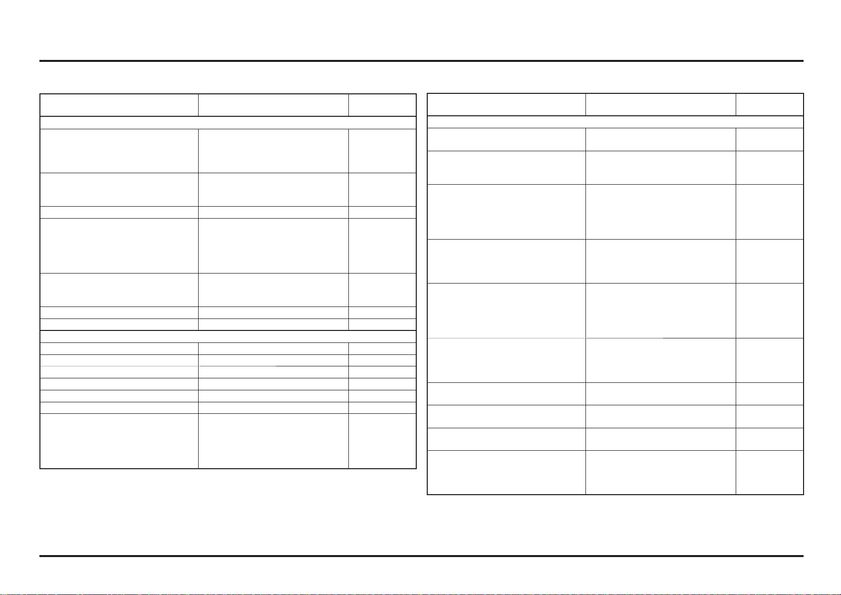
Contents
1. Operating instructions
Operation component locations (2ED).............. 1-1
Operation component locations (4ED).............. 1-2
Fuel ............................................................ 1-3
Coolant ....................................................... 1-3
Basic Operation ............................................ 1-3
Odometer/Speedometer (2ED) ........................ 1-5
Steering lock ................................................ 1-6
Shifting gears .............................................. 1-7
Braking ....................................................... 1-7
Parking ........................................................ 1-8
Controls ...................................................... 1-8
2. Service data
Specifications .............................................. 2-1
Service data ................................................. 2-2
Torque Values .............................................. 2-5
Tools .......................................................... 2-7
Lubrication & Seal Points ............................... 2-8
Cable & Harness Routing (2ED) ...................... 2-11
Cable & Harness Routing (4ED) ...................... 2-12
Cable & Harness Routing ............................... 2-14
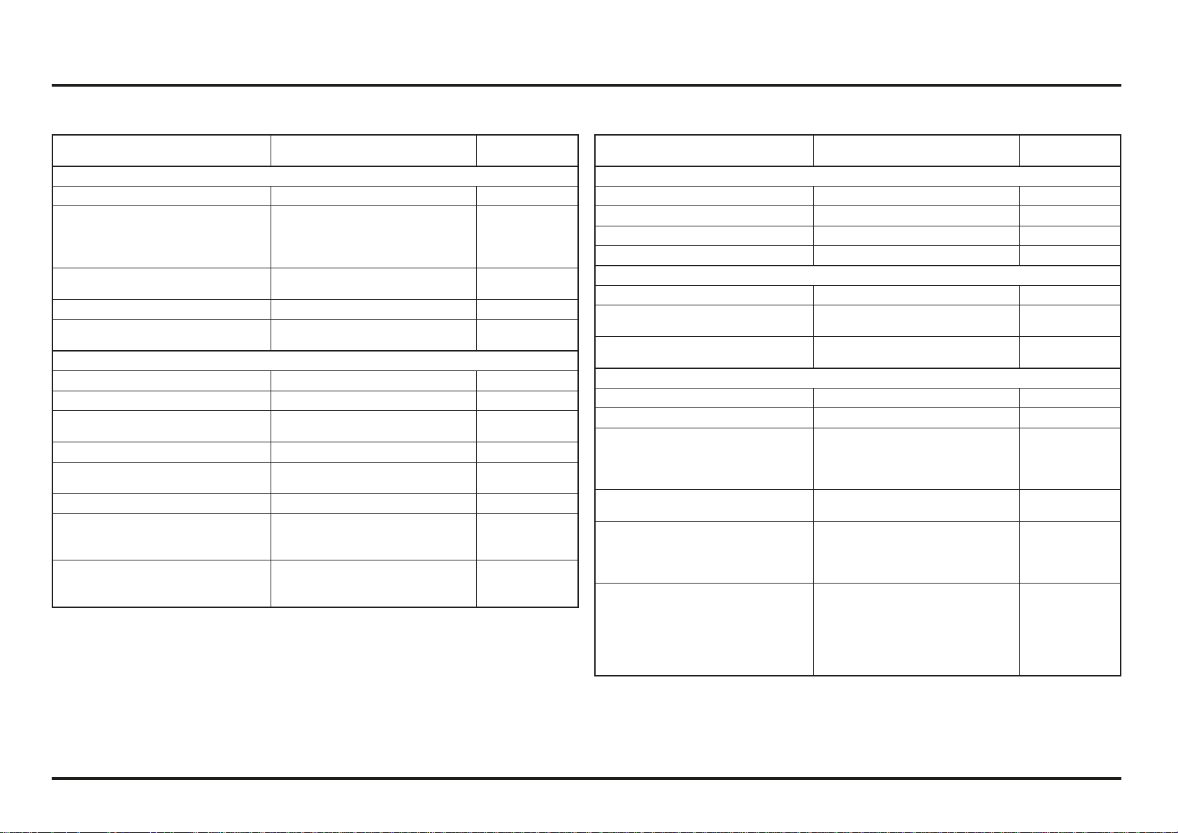
3. Service and maintenance
Maintenance schedule ................................... 3-1
Pre-ride Inspection ........................................ 3-1
Warming-up Inspection .................................. 3-2
Ride Inspection ............................................. 3-2
After Ride Inspection .................................... 3-2
Replacement Parts ........................................ 3-2
Fuel Line ..................................................... 3-3
Air Cleaner .................................................. 3-3
Spark Plug ................................................... 3-4
Valve Clearance ........................................... 3-4
Engine Oil/Oil Filter ....................................... 3-6
Engine Idle Speed ......................................... 3-8
Transmission Oil ........................................... 3-8
Coolant ....................................................... 3-9
Clutch System ............................................. 3-10
Exhaust Pipe And Muffler .............................. 3-10
Drive Chain .................................................. 3-11
Drive Chain Slider ......................................... 3-11
Drive/Driven Sprockets .................................. 3-12
Brake Fluid .................................................. 3-13
Brake Pad Wear ............................................ 3-14
Brake System ............................................... 3-14
Handlebar And Steering Head Bearings ............ 3-15
Wheels And Tires ......................................... 3-15
Front Suspension ..........................................
3-16
Fork
............................................................ 3-16
Rear Suspension ........................................... 3-17
Front headlight and front and rear position light. 3-18
Cleaning ...................................................... 3-19
Storage ....................................................... 3-19
4. Engine servicing
Oil Pressure Relief Valve ................................ 4-1
Oil Pump ..................................................... 4-1
Disassembly / Installation of fuel feed hose .... 4-4
Fuel Line Inspection ...................................... 4-5
Fuel Tank/Fuel Pump ..................................... 4-7
Injector ....................................................... 4-13
Throttle Body ............................................... 4-13
Water Seal And Bearing Replacement .............. 4-15
Radiator Removal/Installation ......................... 4-17
Engine Removal/Installation ............................ 4-18
Cylinder Compression ................................... 4-20
Cylinder Head Removal ................................. 4-23
Cylinder Head Disassembly ............................ 4-25
Cylinder Head Inspection ............................... 4-26
Valve Guide Replacement .............................. 4-27
Valve Seat Inspection/Refacing ...................... 4-28
Cylinder Head Assembly ................................ 4-31
Cylinder/Piston ............................................. 4-32
Cylinder Head Installation .............................. 4-37
Camshaft/Cylinder Head Cover Installation ....... 4-38
Right Crankcase Cover .................................. 4-40
Clutch Slave Cylinder .................................... 4-41
Clutch ......................................................... 4-43
Kickstarter ................................................... 4-46
Gearshift Linkage .......................................... 4-47
Left Crankcase Cover .................................... 4-49
Flywheel ..................................................... 4-52
Crankcase Separation/Disassembly ................. 4-54
Crankshaft/Transmission Inspection ................ 4-56
Crankcase Bearing Replacement ..................... 4-56
Transmission Assembly ................................. 4-58
Crankcase Combination ................................. 4-59
5. Frame servicing
Front Wheel ................................................. 5-1
Fork ............................................................ 5-3
Steering stem .............................................. 5-12
Rear Wheel .................................................. 5-15
Shock Absorber ............................................ 5-16
Shock Linkage .............................................. 5-19
Swingarm ....................................................
5-20
Front Brake Pad Replacement .........................
5-24
Rear Brake Pad Replacement .......................... 5-25
Front brake caliper ........................................ 5-26
Rear brake caliper ......................................... 5-27
Front master cylinder .................................... 5-28
Rear master cylinder ..................................... 5-29
Brake pedal .................................................. 5-29
Clutch master cylinder .................................. 5-30
6. Electrical servicing
Charging system inspection ........................... 6-1
Ignition system inspection ............................. 6-3
PGM-FI System inspection ............................. 6-5
PGM-FI Self-diagnosis malfunction indicator lamp
(MIL) failure codes ........................................ 6-8
Bank angle sensor inspection ......................... 6-9
Engine stop switch inspection ........................ 6-10
Cooling fan system inspection ........................ 6-10
Chapter lights / instruments / switches (2ED) ... 6-11
Speed sensor (2ED) ...................................... 6-15
Horn (2ED) .................................................. 6-16
Wiring diagram (2ED) .................................... 6-17
Wiring diagram (4ED) .................................... 6-18
2020 Montesa Cota RR301
U2NN4PRUMH

How To Use This Manual
The purpose of this Owner’s Manual is to help ensure that
you obtain the greatest possible satisfaction from your
new COTA trialer; satisfaction with the performance of
the motorcycle, and through success in competition.
If you plan to do any service on your COTA, section 3
describes standard maintenance and sections 4 through
6 contain in information on repair, disassembly, assembly
and special tools.
Follow the Maintenance Schedule recommendation
(page 3-1) to ensure that your COTA is always in peak
operating condition.
Importance Of Proper Preparation
Proper pre-competition preparation and regular service
is essential to rider safety and the reliability of the
motorcycle. Any error or oversight made by the technician
during preparation or servicing can easily result in faulty
operation, damage to the machine, or injury to the rider.
Parts Availability
Orders for the parts tend to be concentrated during the
season, so you need to plan your parts orders carefully.
To prevent delays in shipment, place orders on regularly
replaced and fast-wearing parts well ahead of the season
(page 3-2).
To The New Owner
By selecting a MONTESA COTA 301RR as your new
machine, you have placed yourself in a distinguished
family of owners and riders.
The COTA is a high performance trial motorcycle utilizing
the latest trial technology. This motorcycle is intended for
competition use by experienced riders only.
This new trialer was designed to be as competitive as
possible. But motorcycle trial is a physically demanding
sport that requires more than just a fine racing machine.
To do well, you must be in excellent physical condition
and be a skillful rider. For the best possible results, work
diligently on your physical conditioning and practice
frequently.
The purpose of this Manual is to help ensure that you
obtain the greatest possible satisfaction from your new
COTA trialer.
Start-up recommendations
Adjusting the idle
If using your motorcycle at different heights, bear in mind
that you must adjust the idle; otherwise, you may have
problems operating the vehicle. (See page 3-8)
Engine start
If you have problems starting your vehicle, follow the
steps below:
1. Open the throttle all the way (100%) and hold.
2. Without releasing the throttle, operate the kick-starter
once or twice.
3. Close the throttle and start your motorcycle as normal
(page 1-3).

Important
This motorcycle is designed and constructed as an operator-only model. The motorcycle load limit and seating configuration do not safety permit the carrying
of a passenger.
Read this manual carefully.
This manual should be considered as a permanent part of the motorcycle and should remain with the motorcycle when resold.
Safety Messages
Your safety and the safety of others is very important. We have provided
important safety messages in this manual and on the COTA 301RR. Please read
these messages carefully.
A safety message alerts you to potential hazards that could hurt you or others.
Each safety message is preceded by a safety alert symbol and one of three
words, DANGER, WARNING, or CAUTION.
These signal words mean:
!
DANGER
You WILL be KILLED or SERIOUSLY HURT if you
don’t follow instructions.
!
WARNING
You CAN be KILLED or SERIOUSLY HURT if you
don’t follow instructions.
!
CAUTION
You CAN be HURT if you don’t follow instructions.
Each message tells you what the hazard is, what can happen and what you can
do to avoid or reduce injury.
Damage Prevention Messages
You will also see other important messages that are preceded by the word
NOTICE.
This word means:
NOTICE
Your COTA 301RR or other property can be damaged if you don’t follow
instructions.
The purpose of these messages is to help prevent damage to your COTA
301RR, other property, or the environment.
2020
V04

(2ED) Street version, COTA 301RR RACE REPLICA [GREY] (2ED) Street version, COTA 301RR RACE REPLICA [RED]
(4ED) Racing version, COTA 301RR RACE REPLICA [GREY] (4ED) Racing version, COTA 301RR RACE REPLICA [RED]
MONTESA COTA 301RR
Owner’s Manual
The following diagram shows the 4 different versions of the COTA 301RR model:
All information in this publication is based on the latest product information available at the time of approval for printing.
MONTESA HONDA, S.A.U. reserves the right to make changes at any time without notice and without incurring any obligation.
No part of this publication may be reproduced without written permission.
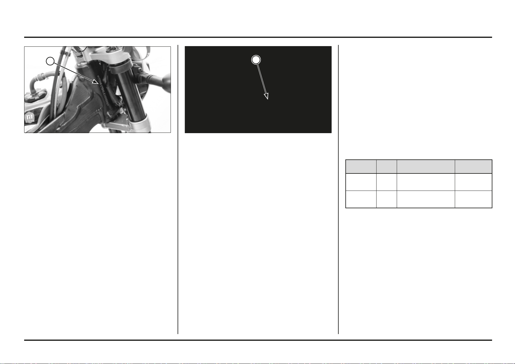
(1) FRAME NUMBER (1) ENGINE NUMBER
Serial numbers
The Vehicle Identification Number (VIN) is stamped on the
right side of the steering head.
The serial number of the engine is stamped on the lower
right side of the crankcase.
MODEL TYPE FRAME No. ENGINE No.
MRT 300 L 2ED VTDND15B?LE000001 NN4E7100001
MRT 300 L 4ED VTDNE053?LE000001 NN4E7100001
1
1
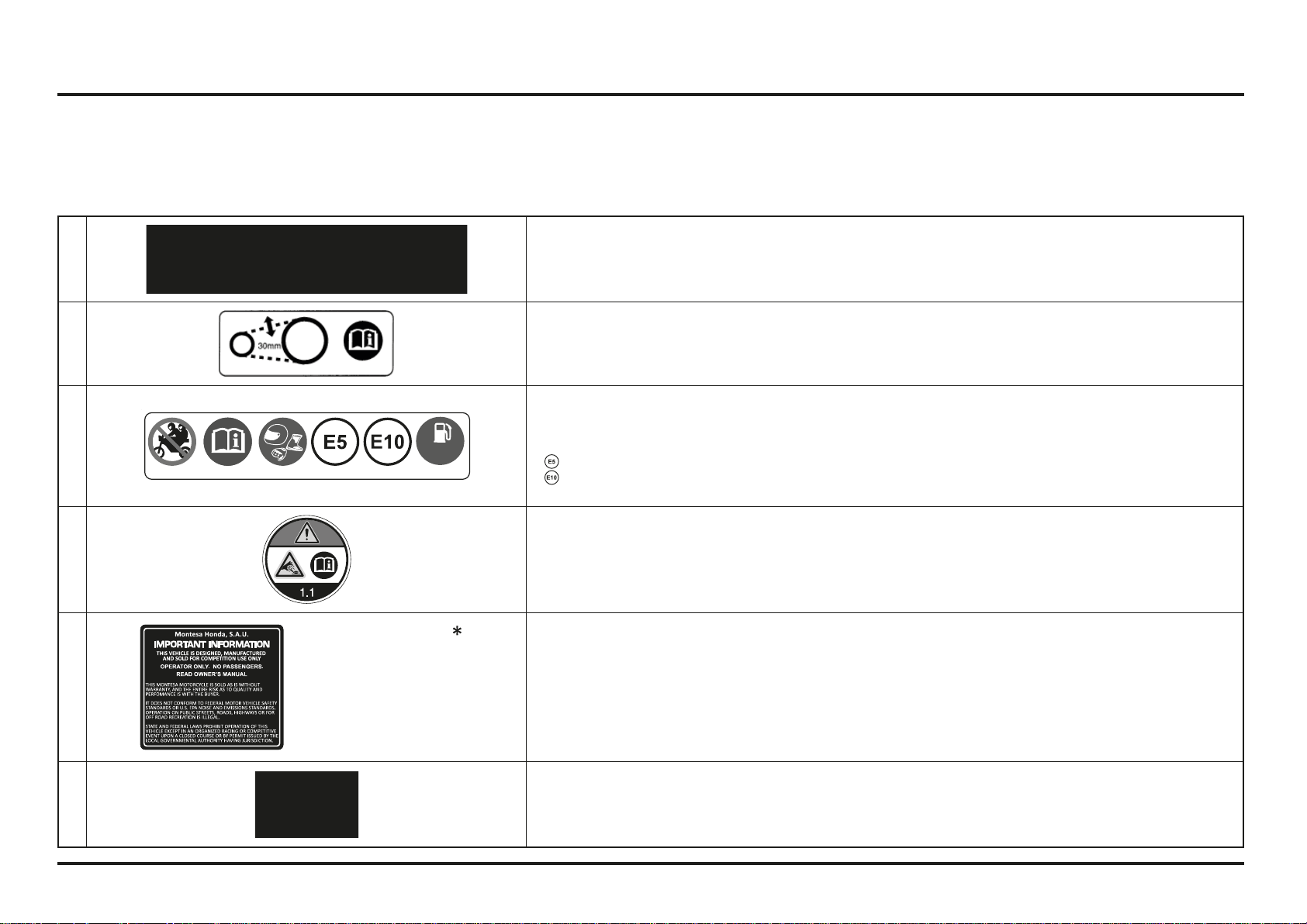
Labels
The following pages show the meanings and locations of the labels on your Cota.
Others provide important safety information. Read this information carefully and don’t remove the labels.
If a label comes off or becomes hard to read, contact your dealer for a replacement.
There is a specific symbol on each label. The meanings of each symbol and label are as follows.
1
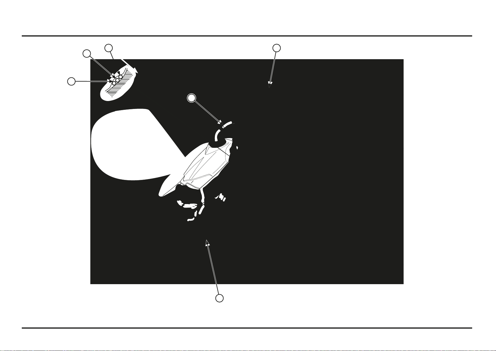
Tire information (2ED)
- Cold tire pressure (driver only)
Front: 100kpa
Rear: 100kpa
2
Keep chain adjusted and lubricated
25-35 Mm (1.0 -1.4 In)
Read owners manual
3
95
+
Caution label
- This motorcycle is not designed to transport a passenger.
- Read owner’s manual carefully.
- For yourprotection always wear your helmet while riding.
-
Ethanol (ethyl alcohol) 5% by volume.
-
Ethanol (ethyl alcohol) 10% by volume.
- Use unleaded gasoline, octane number 95 (RON) or higher.
4
Radiator cap label
Danger
-
Never open when hot.
-
Hot coolant will scald you.
-
Relief pressure valve begins to open at 1.1 Kgf/cm
2
.
5
Safety label (4ED)
(*) Depending on the final destination of the motorcycle
6
EC label
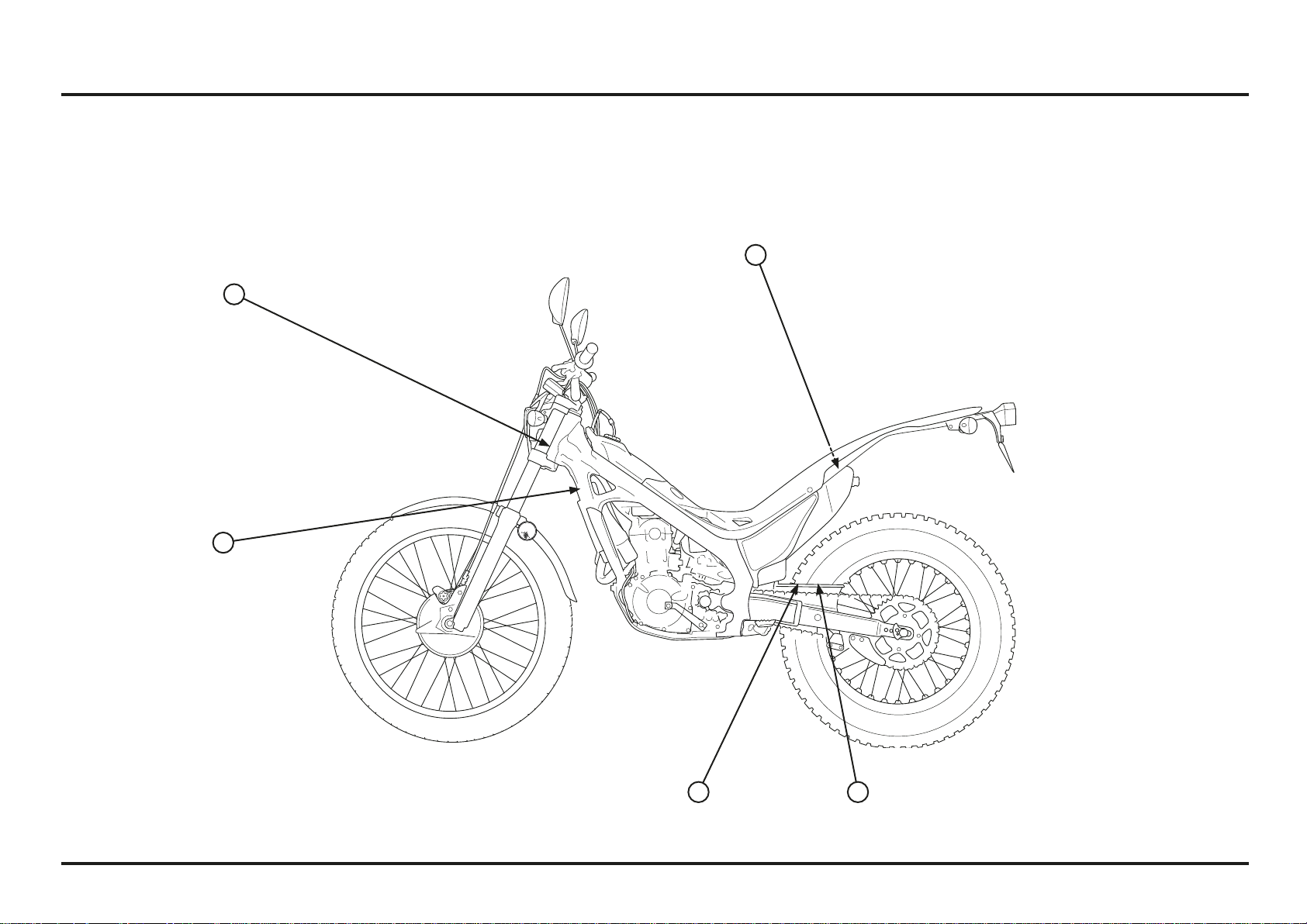
Labels (2ED)
4
21
6
3
Labels (4ED)
5
4
3
2
6
Important Safety Precautions
Your Cota can provide many years of pleasure, if you
take responsibility for your own safety and understand
the challenges you can meet in competitive racing.
As an experienced rider, you know there is much you can
do to protect yourself when you ride.
The following are a few precautions we consider to be
most important.
Never Carry a Passenger.
Your Cota is designed for one operator only.
Carrying a passenger can cause crashes in which you and
others can be hurt.
Wear Protective Gear.
Whether you’re practicing to improve your skills, or riding
in competition, always wear an approved helmet, eye
protection, and proper protective gear.
Take Time to Get to Know Your Cota.
Because every motorcycle is unique, take time to become
thoroughly familiar with how this one operates and
responds to your commands before placing your machine,
and yourself, in competition.
Learn and Respect Your Limits.
Never ride beyond your personal abilites or faster than
conditions warrant. Remember that alcohol, drugs, illness
and fatigue can reduce your ability to perform well and
ride safely.
Don’t Drink and Ride.
Alcohol and riding don’t mix. Even one drink can reduce
your ability to respond to changing conditions, and your
reaction time gets worse with every additional drink. So
don’t drink and ride, and don’t let your friends drink and
ride either.
Keep your Montesa in Safe Condition.
Maintaining your Cota properly is critical to your safety. A
loose bolt, for example, can cause a breakdown in which
you can be seriously injured.
Accessories & Modifications
Modifying your Cota or using non-Montesa accessories
can make your Cota unsafe.
Before you consider making any modifications or adding
an accessory, be sure to read the following information.
!
WARNING
Improper accessories or modifications can cause a
crash in which you can be seriously hurt or killed.
Follow all instructions in this owner’s manual
regarding modifications and accessories.
Accessories
We strongly recommend that you use only Montesa
Genuine accessories that have been specifically designed
and tested for your Cota. Because Montesa cannot test
all other accessories, you must be personally responsible
for proper selection, installation, and use of non-Montesa
accessories.
Check with your dealer for assistance and always follow
this guideline:
Make sure the accessory does not reduce ground clea-
rance and lean angle, limit suspension travel or steering
travel, alter your riding position, or interfere with ope-
rating any controls.
Modifications
We strongly advise you not to remove any original
equipment or modify your Cota in any way that would
change its design or operation.
Such changes could seriously impair your Cota’s handling,
stability, and braking, making it unsafe to ride.
General Competition Maintenance
Perform maintenance on firm, level ground using the side
stand, a workstand, or equivalent support.
When tightening bolts, nuts or screws, start with the
larger diameter or inner fasteners, and tighten them to
the specified torque using a crisscross pattern.
Use Montesa Genuine Parts or their equivalent when
servicing your Cota.
Clean parts in non-flammable (high flash point) cleaning
solvent (such as kerosene) when disassembling. Lubricate
any sliding surface, Orings, and seals before reassembling.
Grease parts by coating or filling where specified.
After any engine disassembly, always install new gaskets,
O-rings, cotter pins, piston pin clips, snap rings, etc. when
reassembling. After reassembly, check all parts for proper
installation and operation.
1-1
1-1
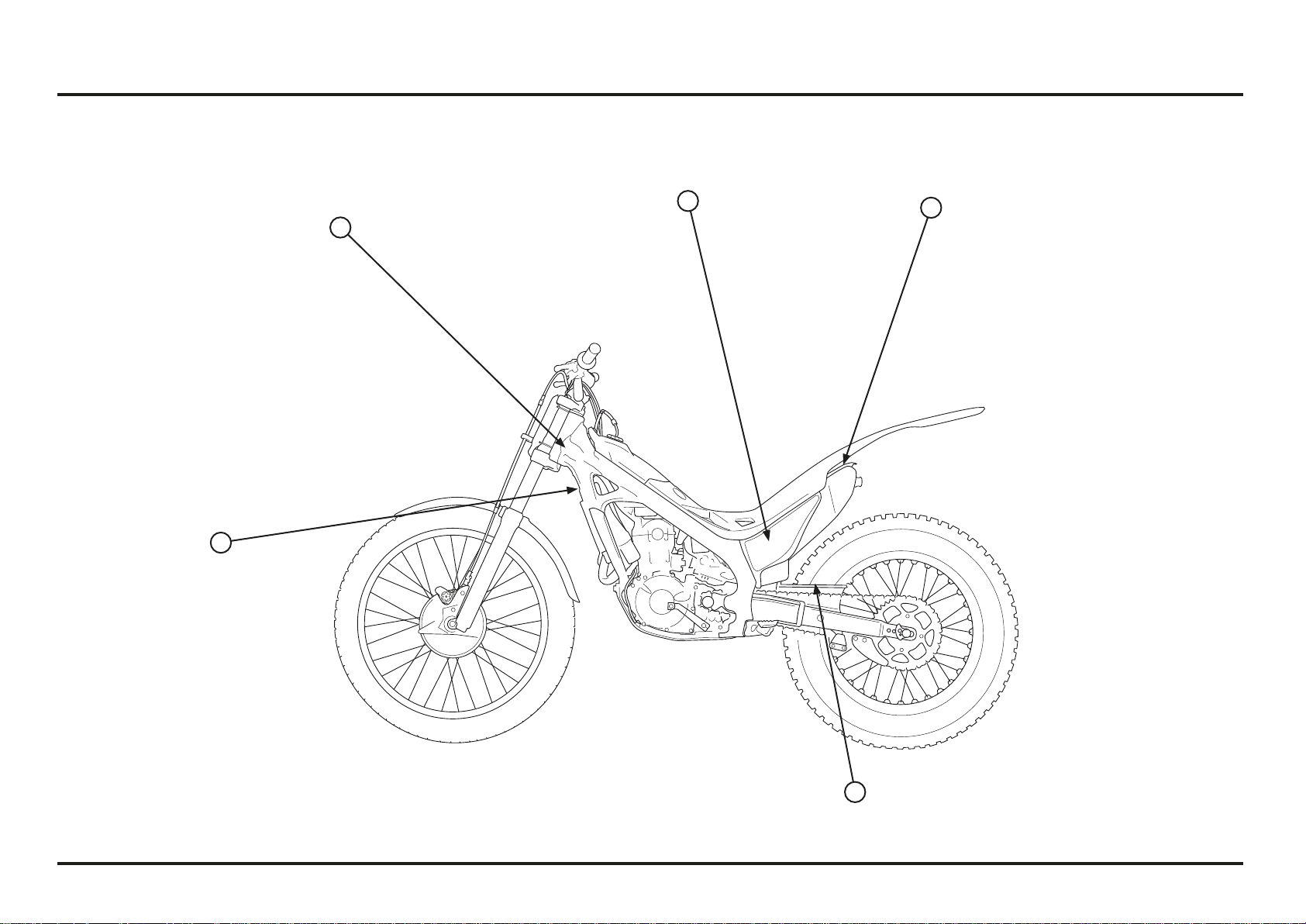
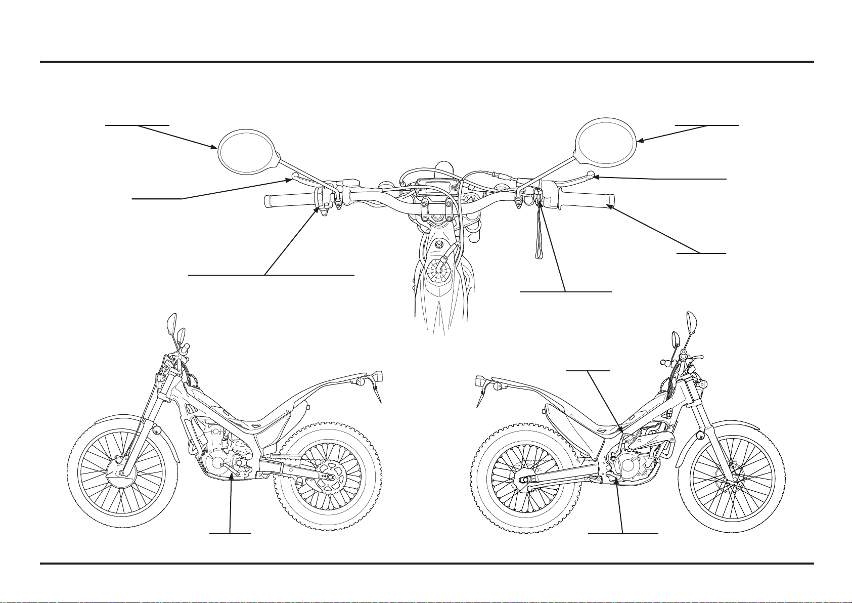
1. Operating instructions
Operation component locations (2ED)
magnetic stop switch
kickstarter
rear brake pedal
clutch lever
front brake lever
throttle grip
rearview mirror rearview mirror
shift lever
light control, turn signal & horn switch
Operating instructions
1-2
1-2
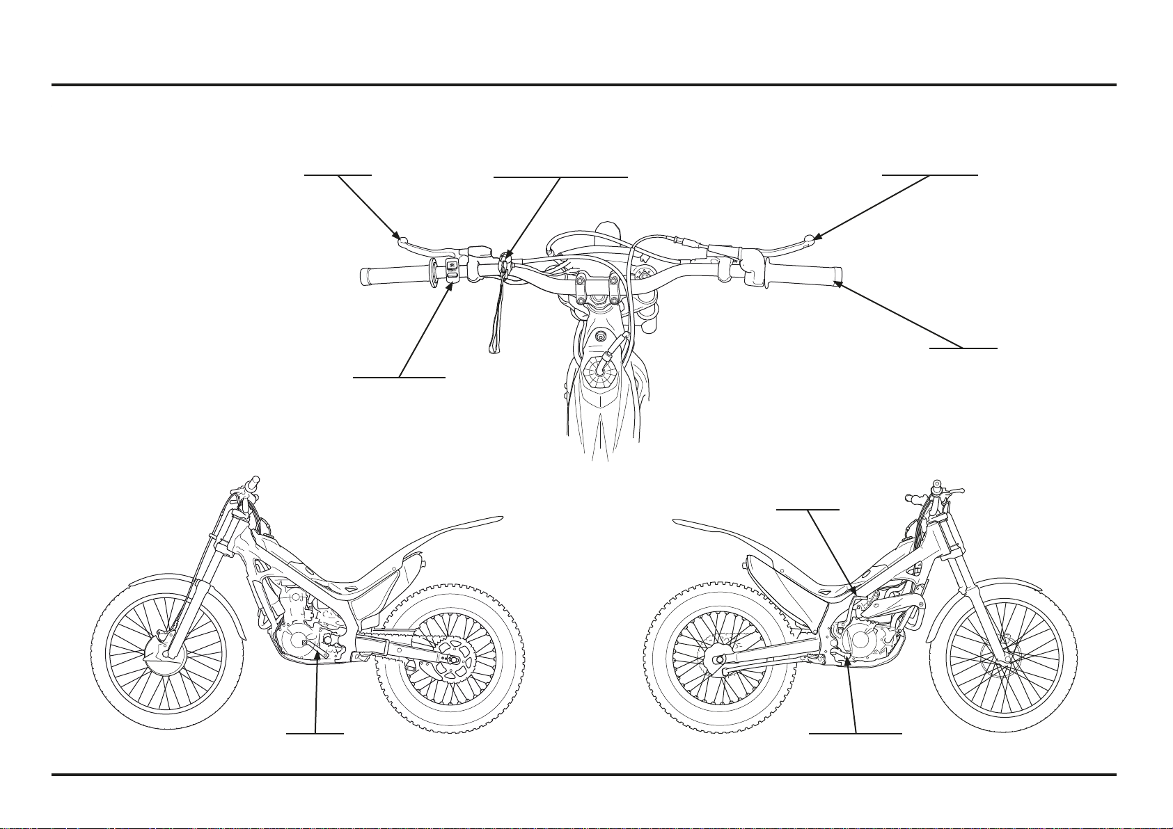
Operation component locations (4ED)
magnetic stop switch
throttle grip
front brake leverclutch lever
shift lever
kickstarter
rear brake pedal
mapping switch
Operating instructions
1-3
1-3
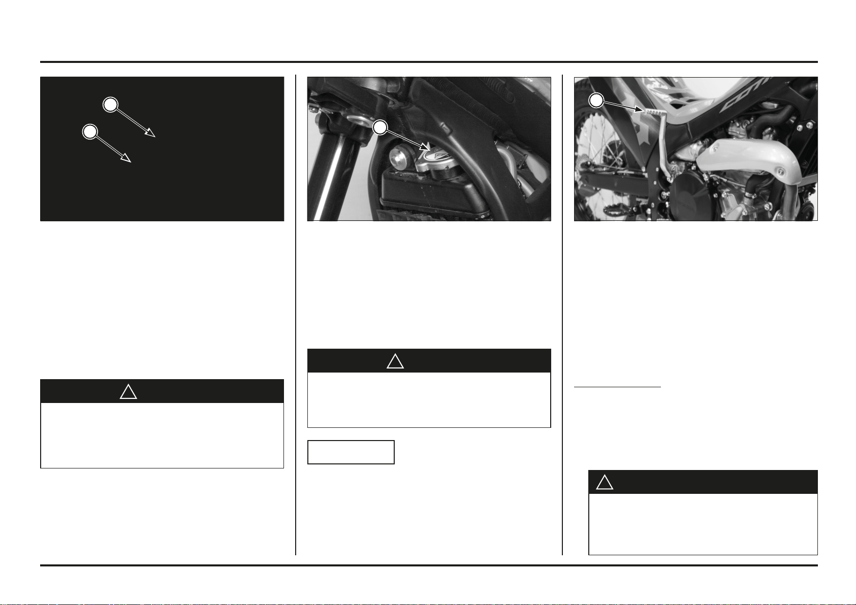
(1) BREATHER HOSE
(2) FUEL TANK CAP
(1) RADIATOR CAP (1) KICKSTARTER PEDAL
Fuel
Gasoline: Unleaded gasoline, pump octane number 95
(RON) or higher
Fuel tank capacity:
2.0 ± 0.2 liter (0.52 US gal, 0.43 Imp gal)
Disconnect the breather hose from the fuel filler cap.
Turn the fuel tank cap counterclockwise, then remove the
cap.
!
WARNING
Gasoline is highly flammable and is explosive.
You can be burned or seriously injured when refueling.
Stop engine and keep heat, sparks, and flame away.
Refuel only outdoors.
Wipe up spills immediately.
Install the fuel tank cap by turning it clockwise.
Connect the breather hose to the fuel filler cap.
Coolant
The engine of COTA is a water-cooled type. In order to
provide adequate cooling, it is essential that the radiator
be filled with coolant up the proper level (See pag. 3-9).
Coolant: 50/50 Mixture of Coolant and Distilled Water
!
WARNING
Removing the radiator cap while the engine is hot will
allow the coolant to spray out, seriously scalding you.
Always let the engine and radiator cool down before
removing the radiator cap.
NOTICE
When fi lling the coolant system, be sure to bleed air
completely. If not, the system cannot be suffi ciently fi lled
and will cause overheating.
Basic Operation
Starting The Engine
Your COTA exhaust contains poisonous carbon monoxide
gas. High levels of carbon monoxide can collect rapidly in
enclosed areas such as a garage. Do not run the engine
with the garage door closed. Even with the door open,
run the engine only long enough to move your COTA out
of the garage.
Cold Engine Starting
1. Shift the transmission to Neutral.
2. Raise the side stand.
3. With the throttle fully closed, operate the kickstarter.
Starting from the top of the kickstarter stroke, kick
through to the bottom with a rapid, continuous motion.
4. After the engine starts, run it for a few minutes,
“blipping” the throttle, until it warms up enough to idle.
!
ATTENTION - VERY IMPORTANT
1
1
2
1
Operating instructions
1-4
1-4
Break-In Procedure
New Motorcycle
Following proper break-in procedure helps ensure that
the most important and expensive components on your
new motorcycle will provide maximum performance and
service life. (Also follow proper break-in procedure for a
newly rebuilt engine.)
When riding a new motorcycle, operate the motorcycle
for the first 20 minutes using not more than half throttle
and shifting gears so that the engine does not lug:
Reconditioned Motorcycle
After replacing the cylinder and crankshaft, operate the
motorcycle 20 minutes observing the same cautions as
for a new motorcycle.
When the piston, piston ring, gears, etc. are replaced,
they must be broken in observing the first 30 minutes
using not more than half throttle and shifting gears so
that the engine does not lug
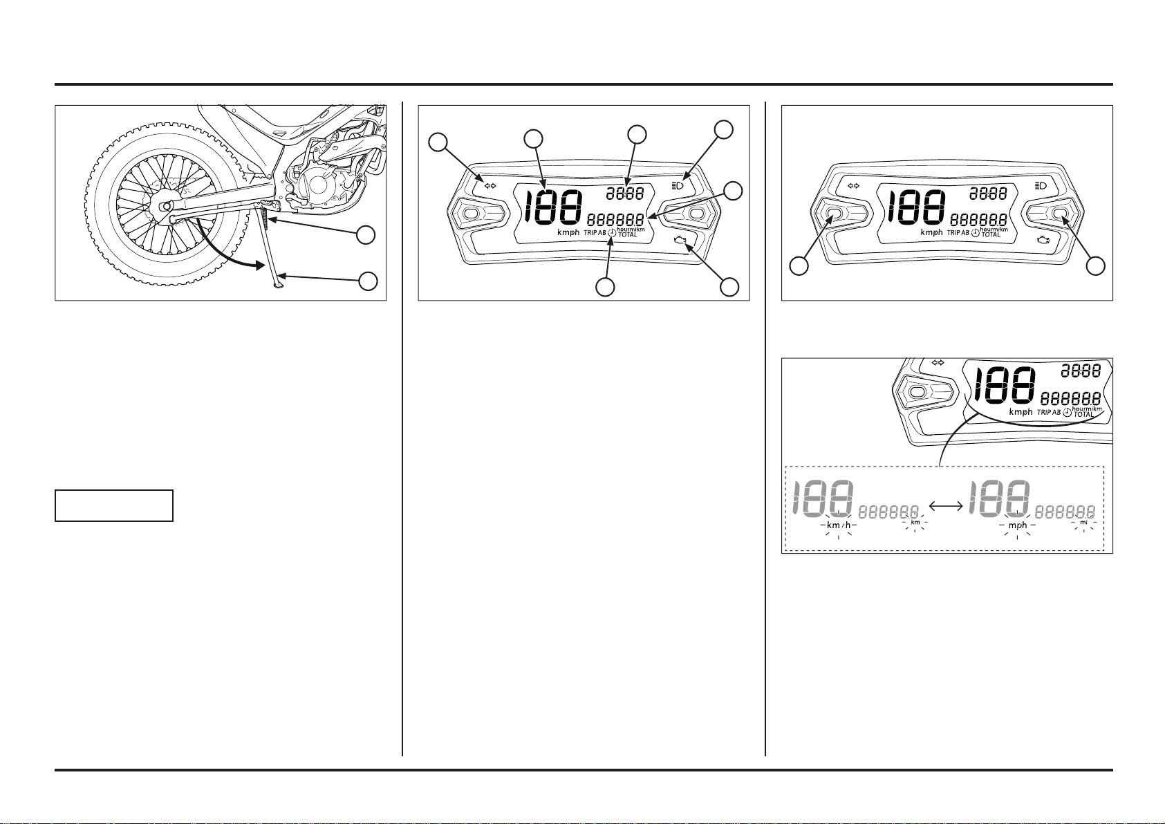
Side Stand
The side stand is used to support your Cota while parked.
To operate, use your foot to lower the side stand until it
is fully extended.
Before riding, raise the side stand.
(1) SIDE STAND
When you shift the transmission into gear, apply front
brake to prevent the motorcycle move forward.
Magnetic Stop Switch
1. Shift the transmission into neutral.
2. Pull the stop magnetic switch (red) until the engine
stops completely.
(1) MAGNETIC STOP SWITCH
4ED
4ED
1
2ED
2ED
1
1
Operating instructions
1-5
1-5
(1) SIDE STAND
(2) SIDE STAND SPRINGS
Inspection
1. Check the stand springs for damage or loss of tension.
2. Check the side stand assembly for freedom of
movement.
If the stand is stiff or squeaks, clean the area around
the pivot and lubricate the pivot bolt with grease or oil
lubricant.
NOTICE
Do not start the motorcycle while supported on the side
stand, which could be bent.
Setting mode
The main screen is used to adjust the following settings:
1. Changing the speed units:
1. Start the motorcycle.
2. Press the (SET) button.
– Press less than 2 seconds to display the ride time
(hour) or mileage (km / mi).
– Press and hold more than 10 seconds, the speed
units will change from km/h to mph and vice versa,
depending on their initial setting.
(1) SPEEDOMETER
(2) ODOMETER
(3) CLOCK
(4) RIDE TIME
(5) TURN SIGNAL INDICATOR
(6) HIGH BEAM INDICATOR
(7) MALFUNCTION INDICATOR LAMP (MIL)
Odometer/Speedometer (2ED)
Instruments
Speedometer: Shows riding speed. This shows your
speed in kilometres per hour (km/h) or miles per hour
(mph).
Odometer: shows accumulated mileage in “TOTAL”,
“TRIP A” and “TRIP B” modes.
Clock: Shows hour and minute.
Ride time: shows the ride time in “TOTAL”, “TRIP A”
and “TRIP B” modes.
Indicators
The indicators are located in the speedometer.
High beam indicator (blue): Lights when the headlight
is on high beam
Turn signal indicator (green): Flashes when the turn
signal operates.
Malfunction indicator lamp (MIL). When any abnorma-
lity occurs in the system, the ECM turns on the MIL.
(1) (MODE) BUTTON
(2) (SET) BUTTON
2ED
2ED
2ED
2ED
2ED
2ED
1
3
2
5
6
7
1
2
4
2
1
Operating instructions
1-6
1-6
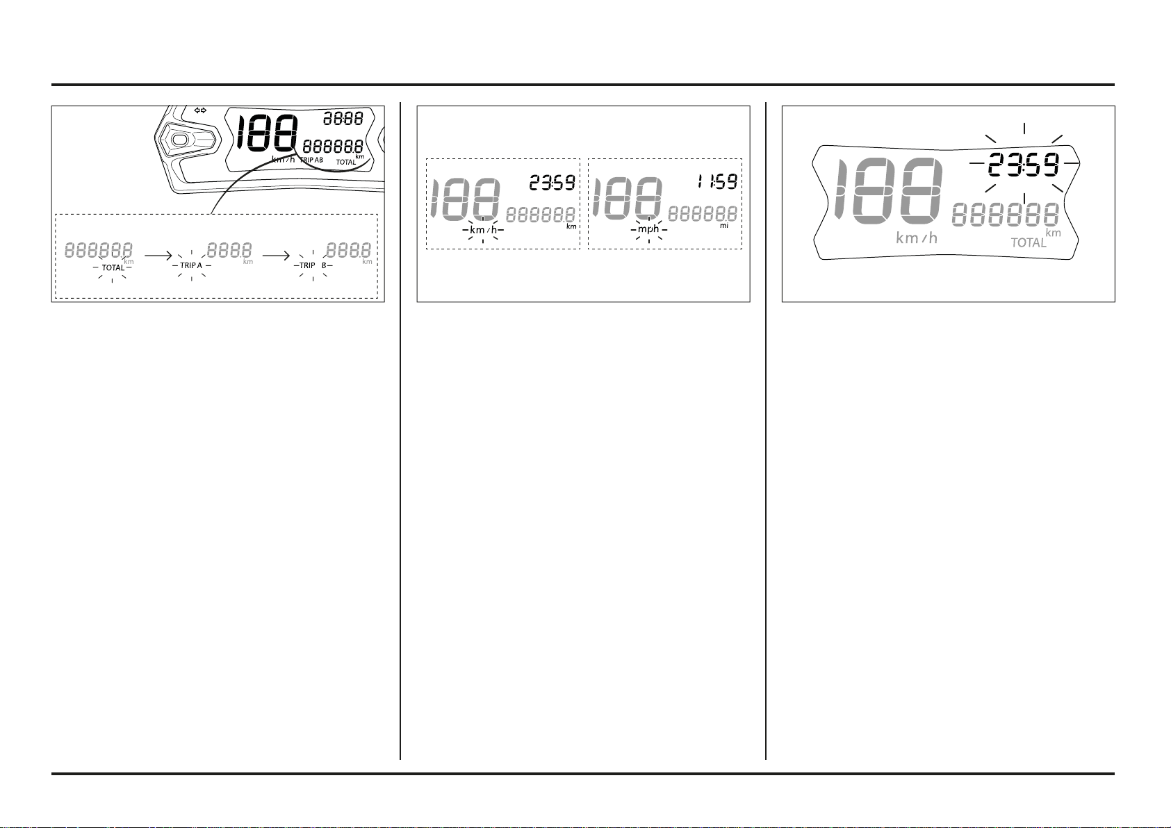
3. Clock settings
The clock will be displayed in 24h format if the unit of
measure is set to km.
The clock will be displayed in 12h format if the unit of
measure is set to mi.
1. Start the motorcycle.
2. Press the (MODE) + (SET) buttons.
– Press and hold more than 2 seconds. The clock will
be set in the adjust mode with the hour display flas-
hing.
– Press the (MODE) button to change the hours.
Press less than 2 seconds, the digit will increase
by one hour each time the button is pressed.
Keep the button pressed, the hour digit advances
fast, release the button when the desired time is
displayed.
- Press the (SET) button to change the minutes.
Press less than 2 seconds, the digit will increase
by one minute each time the button is pressed.
Keep the button pressed, the minute digit advan-
ces fast. Release the button when the desired
minute is displayed.
3. Press the (MODE) + (SET) buttons.
– Press and hold more than 10 seconds to save the
new values and exit the clock setting mode.
– If no button is pressed for more than 10 seconds,
the clock setting mode will end without saving the
changes.
2. Changing from “TOTAL”, “Trip A” o “Trip B”.
1. Start the motorcycle.
The “TOTAL” distance is displayed by default.
2. Press the (MODE) button.
– Press less than 2 seconds to display “TOTAL”,
“TRIP A” o “TRIP B”.
3. Press the (SET) button.
– Press less than 2 seconds to display the ride time
(hour) or accumulated mileage (km / mi).
To reset “TRIP A” or “TRIP B”, select the desired condi-
tion (accumulated mileage or ride time). Press and hold
the (SET) button for more than 2 seconds.
24h 12h
2ED
2ED
2ED
2ED
Operating instructions
1-7
1-7
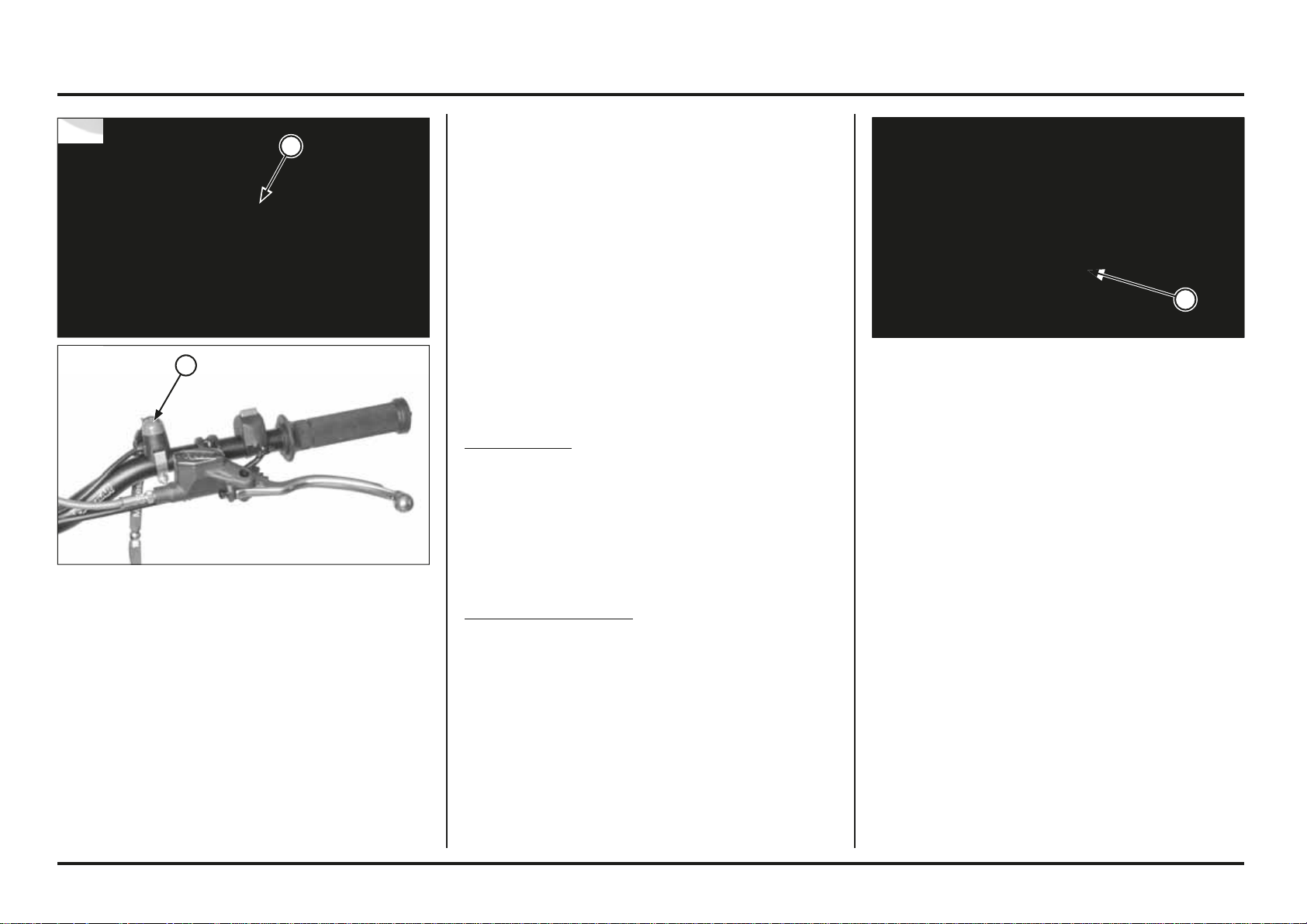
(1) STEERING LOCK
Steering lock (2ED)
The steering lock is on the steering stem. To lock the
steering, turn the handlebar all
the way to the left, insert the steering key into the lock,
turn the key counterclockwise
as far as possible. Then, press the lock all the way in, turn
the key back to the original
position, and remove the key.
To unlock the steering, perform the locking sequence in
the reverse order.
Shifting gears
Your Cota has five forward gears in a one-down, four-up
shift pattern.
To start riding, after the engine has been warmed and the
side stand raised.
1. Close the throttle and pull the front brake lever in.
2. Pull the clutch lever all the way in.
3. Depress the shift lever from neutral down to first gear.
4. Release the front brake lever. Gradually open the
throttle while you slowly release the clutch lever. If the
engine min-1 (rpm) (speed) is too low when you release
the clutch lever, the engine will stall.
If the engine min-1 (rpm) (speed) is too high or you
release the clutch lever too quickly, your Cota may
lurch forward.
5. When you attain a moderate speed, close the throttle,
pull the clutch lever in, and raise the shift lever. After
shifting, release the clutch lever and apply the throttle.
6. To continue shifting up to each higher gear, repeat step 5.
7. To shift down to a lower gear, close the throttle, pull
the clutch lever in, and depress the shift lever. After
shifting, release the clutch lever and apply the throttle.
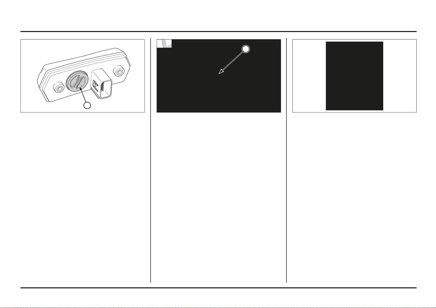
4. Coin battery
Odometer/Speedometer is equipped with a coin battery
for keeping time when motorcycle is off.
Coin size: CR2032
(1) COIN BATTERY
1
2ED
2ED
1
Operating instructions
1-8
1-8
Controls
Clutch
Your COTA has a hydraulically actuated clutch. There are
no adjustments to perform but the clutch system must be
inspected periodically for fluid level and leakage.
If the control lever free play becomes excessive and the
motorcycle creeps or stalls when shifted into gear, or if
the clutch slips, causing acceleration to lag behind engine
speed, there is probably air in the clutch hydraulic system
and it must be bled out.
(1) UPPER LEVEL LINE
Braking
To slow or stop, apply the front brake lever and rear brake
pedal smoothly, while downshifting to match your speed.
Gradually increase braking as you feel the brakes slowing
your speed. To prevent stalling the engine, pull the clutch
lever in before coming to a complete stop. For support,
put your left foot down first, then your right foot when
you are through using the rear brake pedal.
For maximum braking, close the throttle and firmly apply
the front brake lever and rear brake pedal controls.
Applying the brakes too hard may cause the wheels to
lock and slide, reducing control of your Cota. If this hap-
pens, release the brake controls, steer straight ahead until
you regain control, then reapply the brakes more gently.
Generally, reduce your speed or complete braking befo-
re beginning a turn. Avoid braking or closing the throttle
quickly while turning. Either action may cause one or both
wheels to slip. Any wheel slip will reduce your control of
your Cota.
When riding in wet or raining conditions, or on loose sur-
faces, the ability to maneuver and stop will be reduced.
All of your actions should be smooth under these condi-
tions. Rapid acceleration, braking, or turning may cause
loss of control. For your safety, exercise extreme caution
when braking, accelerating, or turning.
When descending a long, steep grade, use engine com-
pression braking by downshifting, with intermittent use
of both brakes.
When you brake to a stop, pull the clutch lever in before
stopping completely to prevent stalling the engine. For
support, put your left foot on the ground first, then your
right foot when you have finish braking.
Remember to close the throttle and pull the clutch lever in
completely before shifting.
NOTICE
Improper shifting may damage the engine, transmission,
and drive train.
Learning when to shift gears comes with experience.
Upshift to a higher gear or reduce throttle before engine
min-1 (rpm) (speed) gets too high. Downshift to a lower
gear before you feel the engine laboring (lugging) at low
min-1 (rpm).
NOTICE
Downshifting can help slow your motorcycle, especially
on downhills. However, downshifting when engine min-1
(rpm) is too high can cause engine damage.
NOTICE
To prevent transmission damage, do not coast or tow the
motorcycle for long distances with the engine off.
NOTICE
If you put the motorcycle in gear with the side stand
down, the engine will shut off.
Parking
Lower the side stand to support your Cota.
Always choose a level surface to park.
1
Operating instructions
1-9
1-9
Clutch Lever
The clutch lever free play can be adjusted by turning the
adjuster.
Free play must be adjusted to provide 0.5 – 1.5 mm
(0.019 – 0.060 in) clearance between the end of the
adjuster and the clutch master cylinder piston.
To reduce free play, turn the adjuster clockwise, then
tighten the lock nut securely.
To increase free play, turn the adjuster counterclockwi-
se, then tighten the lock nut securely.
If the clutch will not disengage or motorcycle creeps
with clutch disengaged,there is probably air in the clutch
system and it must be bled.
NOTICE
Do not adjust the end of the adjuster and the clutch mas-
ter cylinder piston below 0.5 mm (0.019 in).
Clutch Lever Free Play
Standard cluth lever free play should be between
0.5 – 15 mm (0.019 – 0.60 in).
NOTICE
Do not adjust the free play of the lever to less than 5 mm
(0.196 in).
(1) ADJUSTER
(2) LOCK NUT
(1) CLUTCH LEVER
(2) FREE PLAY
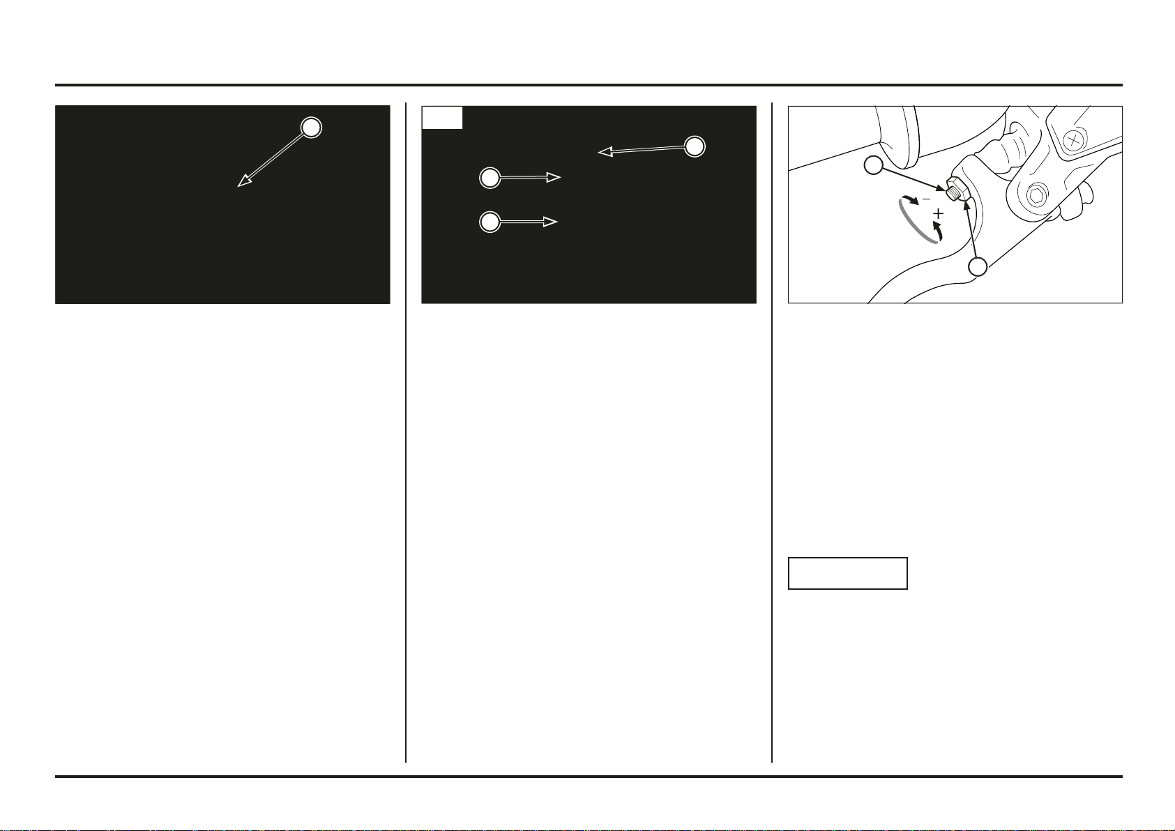
Throttle Grip
Throttle Grip Free Play
Standard throttle grip free play is approximately 3 mm
(0.12 in) of grip rotation.
Adjustment is made with the integral throttle cable
adjuster.
Slide the dust cover off from the integral cable adjuster.
Turning the adjuster in direction “A” will decrease free
play and turning it in direction “B” will increase free play.
Tighten the lock nut after adjustment.
Operate the throttle grip to ensure that it functions
smoothly and returns completely in all steering position.
(1) DUST COVER (A) DECREASE
(2) LOCK NUT (B) INCREASE
(3) ADJUSTER
1
A
B
2
3
1
2
2
1
Operating instructions
1-10
1-10
(1) HORN BUTTON
Horn button
Press the button to sound the horn.
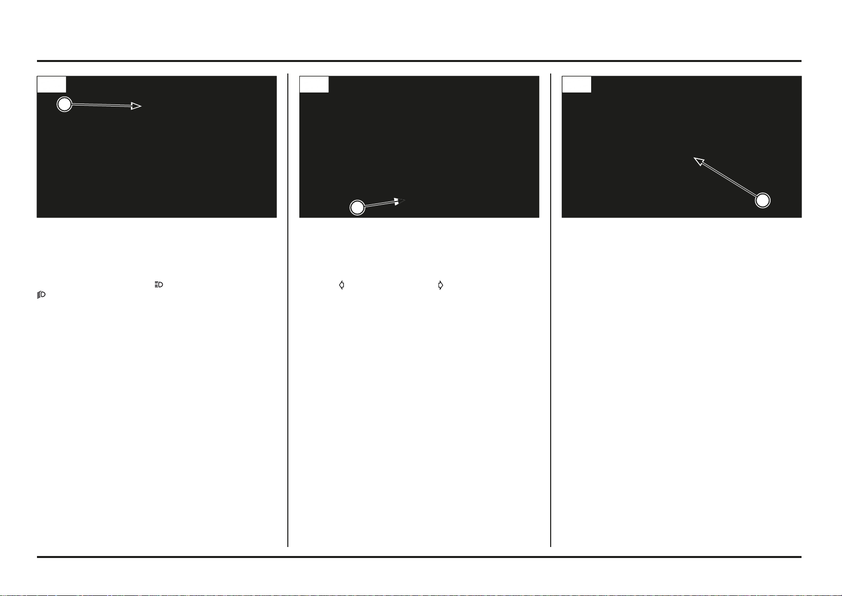
(1) HEADLIGHT DIMMER SWITCH (1) TURN SIGNAL SWITCH
Headlight dimmer switch
Turn the dimmer switch to
to select high beam or to
to select low beam.
Turn signal switch
Move to
to signal a left turn, to signal a right turn.
Press to turn signal off.
1
2ED
2ED
1
1
2ED
2ED
2ED
2ED
Operating instructions
1-11
1-11
Mapping switch
The ECU for the Cota 301RR (4ED) PGM-FI electronic in-
jection system has two operational maps which can be
selected depending on the conditions:
Switch in Mode 1:
Standard
Switch in Mode 2:
Powered
(1) MAPPING SWITCH
(2) MODE 1
(3) MODE 2
Magnetic stop switch
Pull the stop magnetic switch (red) until the engine stops
completely.
(1) MAGNETIC STOP SWITCH
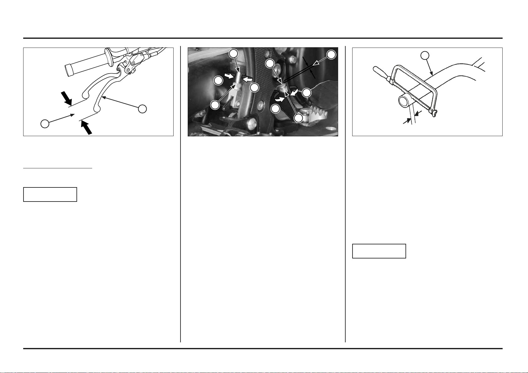
Front brake lever
The front brake lever free play can be adjusted by turning
the adjuster.
Free play must be adjusted to provide 0.5 – 1.5 mm
(0.019 – 0.060 in) clearance between the end of the ad-
juster and the front brake master cylinder piston.
To reduce free play, turn the adjuster clockwise, then
tighten the lock nut securely.
To increase free play, turn the adjuster counterclockwi-
se, then tighten the lock nut securely.
If brake lever feels soft or spongy, there is probably air in
the brake system and it must be bled.
NOTICE
Do not adjust the end of the adjuster and the front brake
master cylinder piston below 0.5 mm (0.019 in).
(1) ADJUSTER
(2) LOCK NUT
1
3
2
4ED
4ED
1
2
1
Operating instructions
1-12
1-12
(1) HANDLEBAR
Handlebar position, width and shape
Position the handlebar so that gripping the bar and ope-
rating the controls is comfortable while both seated and
standing, while riding straight ahead and turning.
Handlebar width can be trimmed with a hacksaw to bet-
ter your particular shoulder width and riding preference.
Think this though carefully and cut off just a small amou-
nt at a time from both side equally. It is obviously much
easier to make the handlebar narrower than it is to add
material.
NOTICE
Chamfer the edges to remove burrs and other irregulari-
ties or roughness after shaping.
An alternate handlebar shape. through varying rise or re-
arward sweep dimensions, will provide further adjustment
to riding position and may better suit your particular body
size or riding style. Each of the ergonomic dimensions
of the motorcycle were determined to suit the greatest
possible number of riders based on an average size rider.
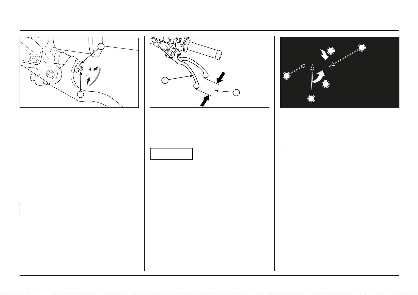
(1) LOCK NUT
(2) ROD
(3) ADJUSTING BOLT
(4) FREE PLAY
Brake pedal height
The brake pedal height can be adjusted to the rider’s
preference.
To adjust the rear brake pedal height:
1. Loosen the push rod lock nut and brake pedal adjusting
bolt lock nut. Then turn the both adjusting bolts in
direction “A” to raise the pedal, or in direction “B” to
lower it.
2. Tighten the lock nuts at the desired pedal height.
3. After adjustment, check the brake pedal free play at
the top of the pedal.
Make sure that the clearance between the front adjusting
bolt and frame is at least 1~2 mm (0.04~0.08 in).
Front brake lever free play
Standard front brake lever free play should be
between 0.5 – 15 mm (0.019 – 0.60 in).
NOTICE
Do not adjust the free play of the lever to less than 5 mm
(0.196 in).
(1) FRONT BRAKE LEVER
(2) FREE PLAY
1
1
2
A
A
B
B
1
1
2
3
4
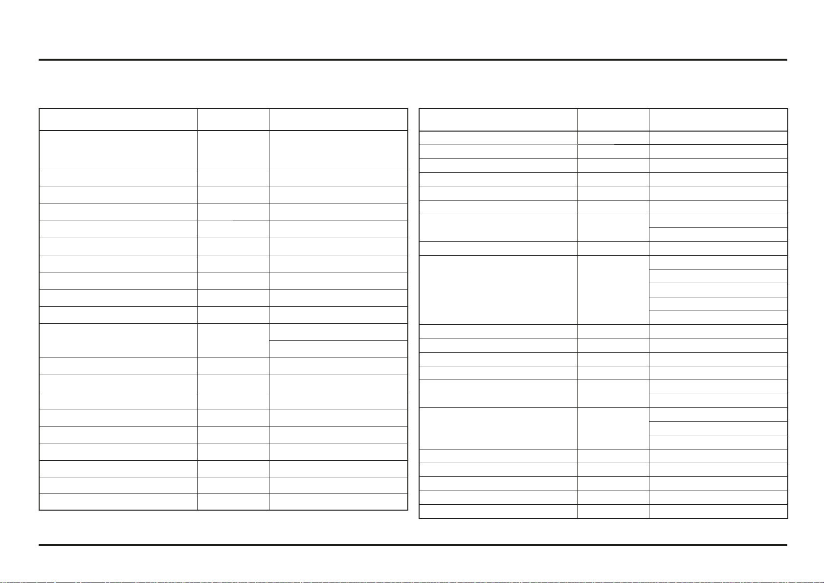
2. Service data
Specifications
2-1
2-1
Item Specification
Dimensions
Overall length 2,020 mm
Overall width 840 mm
Overall height 1,135 mm
Wheelbase 1,320 mm
Seat height 677 mm
Ground clearance 300 mm
Frame
Type Aluminium twin tube
Front suspension Telescopic
Rear suspension Swingarm PRO-LINK
Front tire MICHELIN TRIAL COMPETITION
(2,75-21 M/C 45L)
DUNLOP D803FGP
(80/100-21 M/C 51M)
Rear tire MICHELIN TRIAL COMPETITION X11
(4.00 R18 M/C 64L)
DUNLOP D803GP
(120/100R18 M/C 68M)
Front brake. diameter Single disc. 184 mm
Rear brake. diameter Single disc. 150 mm
Fuel capacity 2.0 ± 0.2 liter
Caster angle 24º 34’
Trail length 63 mm
Engine
Type Liquid cooled 4–stroke engine
Cylinder arrangement Single cylinder. 3.5˚ inclined from vertical
Bore and stroke 81.5 x 57.2 mm
Displacement 298 cm
3
Compression ratio 10.4 : 1
Valve timing
Intake valve opens
Intake valve closes
Exhaust valve opens
Exhaust valve closes
9˚ BTDC
27˚ ABDC
37˚ BBDC
5˚ ATDC
(at 1.0 mm lift)
Lubrication system Forced pressure and wet sump
Starting system Primary kickstarter
Item Specification
Fuel System
Type PGM-FI
Identification number GQPMC (2ED)
GQPMD (4ED)
Throttle bore 28 mm
Drive Train
Clutch operating system Hydraulic operated
Clutch type Wet. multi-plate
Transmission 5 speed constant mesh
Primary reduction 3.167 (57/18T)
Gear ratio 1st 2.800 (42/15T)
2nd 2.385 (31/13T)
3rd 2.000 (30/15T)
4th 1.273 (28/22T)
5th 0.815 (22/27T)
Final reduction 4.100 (41/10T)
Gearshift pattern 1 – N – 2 – 3 – 4 – 5
Electrical
Alternator Triple phase output alternator
Ignition system PGM-IGN
Regulator type SCR shorttriple phase. full wave rectification
Service data
2-2
2-2
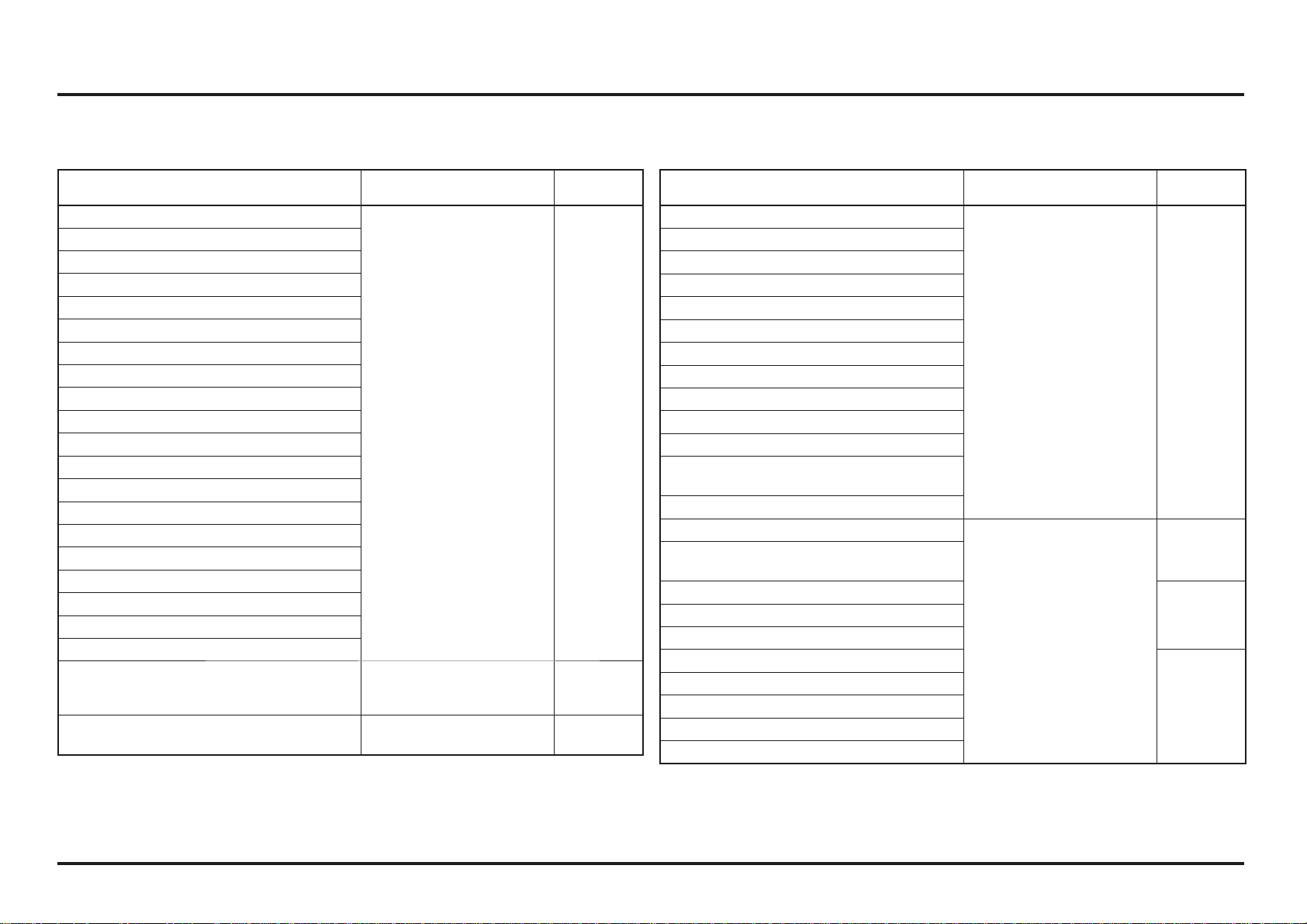
Service data
Item Specification
Lubrication
Specified engine oil
Repsol 4T oil-stroke motorcycle oil SAE 10W-30 or
equivalent
Engine oil capacity
after draining
after oil filter change
after disassembly
0.41 liter (0.43 US qt. 0.36 Imp qt)
0.44 liter (0.46 US qt. 0.39 Imp qt)
0.60 liter (0.63 US qt. 0.53 Imp qt)
Specified transmission oil
REPSOL MOTO TRANSMISSION (75W)
ELF HTX740 (75W)
Transmission oil capacity
after draining
after disassembly
0.54 liter (0.57 US qt. 0.48 Imp qt)
0.57 liter (0.60 US qt. 0.50 Imp qt)
Fuel System
Throttle body identification No.
GQPMC (2ED)
GQPMD (4ED)
Throttle grip free play 3 mm
Engine idle speed 1,800 ± 100 min-1 (rpm)
Fuel pressure 314 - 382 kPa (3.2 - 3.9 kgf/cm
2
)
Fuel pump flow at 12 V 125 cm
3
minimum/10 seconds
Injector resistance 11.1 – 12.3 Ω (20˚C/68˚F)
Cooling System
Recommended coolant 50/50 mixture coolant and distilled water
Radiator cap relief pressure 108 kPa (1.1 kgf/cm
2
)
Presión de alivio tapón del radiador 108 kPa (1.1 kgf/cm2)
Unit: mm (in)
Item Standard Service limit
Cylinder Head/Valves
Cylinder compression 1,300 kPa (13.2 kgf/cm
2
, 189 psi) –
Cylinder head warpage – 0.05 (0.002)
Valve stem O.D.
IN
EX
0.12 ± 0.03 (0.005 ± 0.001)
0.30 ± 0.03 (0.012 ± 0.001)
–
–
IX
EX
4.475 – 4.490 (0.1762 – 0.1768)
4.465 – 4.480 (0.1758 – 0.1764)
4.470 (0.1760)
4.460 (0.1756)
Valve guide I.D. IN/EX 4.500 – 4.512 (0.1772 – 0.1776) 4.552 (0.1792)
Valve stem-to-guide clearance
IN
EX
0.010 – 0.037 (0.0004 – 0.0015)
0.020 – 0.047 (0.0008 – 0.0019)
–
–
Valve guide projection above
cylinder head
IN
EX
8.0 – 8.3 (0.31 – 0.33)
8.2 – 8.5 (0.32 – 0.33)
–
–
Valve spring free length
Inner
Outer
25.41 (1.000)
28.32 (1.115)
24.9 (0.98)
27.6 (1.09)
Rocker arm I.D. 10.000 – 10.015 (0.3937 – 0.3943) 10.051 (0.3957)
Rocker arm shaft O.D. 9.972 – 9.987 (0.3926 – 0.3932) 9.925 (0.3907)
Rocker arm-to-shaft clearance 0.013 – 0.043 (0.0005 – 0.0017) 0.11 (0.04)
Cam lobe height
AD
ES
32.011 – 33.051 (1.2603 – 1.3012)
32.855 – 32.935 (1.2935 – 1.2967)
31.871 (1.2548)
32.748 (1.2893)
Service data
2-3
2-3
Item Standard Service limit
Cylinder/Piston
Cylinder I.D
Taper
Out-of- round
Warpage
81.500 – 81.515 (3.2086 – 3.2092)
–
–
–
81.540 (3.2102)
0.05 (0.002)
0.05 (0.002)
0.05 (0.002)
Piston O.D.
Measurement point
Pin bore I.D.
81.470 – 81.480 (3.2074 – 3.2078)
3.0 (0.118) from bottom of skirt
16.006 – 16.010 (0.6301 – 0.6303)
81.440 (3.2062)
–
16,02 (0,6307)
Piston pin O.D. 15.997 – 16.000 (0.6298 – 0.6299) 15.99 (0.6295)
Piston ring
End gap
Top
Second
Oil (side rail)
0.20 – 0.30 (0.008 – 0.0118)
0.35 – 0.50 (0.0137 - 0.0197)
0.20 – 0.70 (0.008 – 0.028)
0.44 (0.0173)
0.64 (0.0251)
0.90 (0.0354)
Ring-to-groove clearance
Top
Second
0.070 – 0.110 (0.028 – 0.0043)
0.020 – 0.060 (0.008 – 0.0236)
0.115 (0.0045)
0.065 (0.0026)
Cylinder-to-piston clearance 0.020 – 0.045 (0.008 – 0.0177) 0.08 (0.003)
Piston-to-piston pin clearance 0.006 – 0.013 (0.0002 – 0.0005) 0.03 (0.0011)
Clutch/Gearshift Linkage
Recommended clutch fluid DOT 4 brake fluid –
Clutch spring free length 27.6 (1.09) 26.8 (1.06)
Clutch disc thickness 3.22 – 3.38 (0.127 – 0.133) 3.15 (0.124)
Clutch plate warpage – 0.10 (0.004)
Clutch slave cylinder I.D. 27.000 – 27.021 (1.0630 – 1.0638) –
Clutch slave piston O.D. 26.940 – 26.960 (1.0606 – 1.0614) –
Kickstarter
Spindle O.D.
Pinion gear I.D.
Idle gear I.D.
Countershaft O.D. at kickstarter idle gear
16.466 – 16.484 (0.6483 – 0.6490)
16.516 – 16.534 (0.6502 – 0.6509)
17.016 – 17.034 (0.6699 – 0.6706)
16.983 – 16.994 (0.6686 – 0.6691)
16.46 (0.648)
16.55 (0.652)
17.06 (0.672)
16.97 (0.668)
Unit: mm (in) Unit: mm (in)
Item Standard Service limit
Crankshaft/Transmission
Crankshaft runout Right
Left
–
–
0.03 (0.001)
0.05 (0.002)
Connecting rod big end
Side clearance
Radial clearance
0.30 – 0.75 (0.012 – 0.030)
0.06 – 0.18 (0.002 – 0.007)
0.8 (0.03)
0.05 (0.002)
Transmission gear I.D. M4
M5
C1
C2
C3
23.020 – 23.041 (0.9063 – 0.9071)
23.020 – 23.041 (0.9063 – 0.9071)
20.020 – 20.041 (0.7882 – 0.7890)
25.020 – 25.041 (0.9850 – 0.9859)
25.020 – 25.041 (0.9850 – 0.9859)
23.07 (0.908)
23.07 (0.908)
20.06 (0.790)
25.06 (0.987)
25.06 (0.987)
Gear bushing D.I. M5
C1
C2
C3
20.000 – 20.021 (0.7866 – 0.7882)
17.000 – 17.018 (0.6693 – 0.6700)
22.000 – 22.021 (0.8661 – 0.8670)
22.000 – 22.021 (0.8661 – 0.8670)
20.05 (0.789)
17.04 (0.671)
22.04 (0.868)
22.04 (0.868)
O.D. M4
M5
C1
C2
C3
22.979 – 23.000 (0.9047 – 0.9055)
22.979 – 23.000 (0.9047 – 0.9055)
19.979 – 20.000 (0.7866 – 0.7874)
24.979 – 25.000 (0.9834 – 0.9843)
24.979 – 25.000 (0.9834 – 0.9843)
22.96 (0.904)
22.96 (0.904)
19.95 (0.785)
24.95 (0.982)
24.95 (0.982)
Countershaft O.D.
at C1 bushing
at C2/C3 bushing
at kickstarter idle gear
16.983 – 16.994 (0.6686 – 0.6691)
21.959 – 21.980 (0.8645 – 0.8654)
16.983 – 16.994 (0.6686 – 0.6691)
16.97 (0.668)
21.94 (0.864)
16.97 (0.668)
Shift fork I.D. C
R. L
11.003 – 11.024 (0.4332 – 0.4330)
12.035 – 12.056 (0.4738 – 0.4746)
11.04 (0.435)
12.07 (0.475)
Shift fork claw thickness C
R. L
4.93 – 5.00 (0.194 – 0.197)
4.93 – 5.00 (0.194 – 0.197)
4.8 (0.19)
4.8 (0.19)
Shift fork shaft O.D. C
R. L
10.983 – 10.994 (0.4324 – 0.4328)
11.966 – 11.984 (0.4711 – 0.4718)
10.97 (0.432)
11.95 (0.470)
Oil pump
Tip clearance
Body clearance
Side clearance
–
0.15 – 0.20 (0.006 – 0.008)
0.05 – 0.12 (0.002 – 0.004)
0.20 (0.008)
–
–
Service data
2-4
2-4
Unit: mm (in)
Item Standard Service Limit
Wheels/Tires
Axle runout 0.20 (0.008)
Tire air pressure
For road use
Comptetion use only Front
Rear
100 kPa (1.01 kgf
/
cm
2
)
39 – 44 kPa (0.40 – 0.45 kgf
/
cm
2
)
29 – 34 kPa (0.30 – 0.35 kgf
/
cm
2
)
–
–
–
Wheel rim runout Radial
Axial
–
–
2.0 (0.08)
2.0 (0.08)
Drive chain slack 25 – 35 (1.0 – 1.4) –
Drive chain slider thickness –
2.0 (0.08) from
upper surface
Front Suspension TECH
Left fork spring free length 415 (16.3) 408 (16.0)
Fork tube runout 0.35 – 0.50 (0.014 – 0.020) 0.20 (0.008)
Recommended fork fluid
OJ Racing Special Fork Oil Type 01
(SAE 5W) or equivalent
Pre-load adjuster setting 5±0.5 turns out from full soft –
Damping adjuster setting
Tension adjuster:
16±2 clicks from full hard
–
Comp. Stop adjustment (left fork) 1,5±0,5 turns out from full hard –
Fork oil level
Right
Left
70 (2.7)
125 (4.9)
–
–
Fork oil capacity
Right
Left
260 cm
3
285 cm
3
–
–
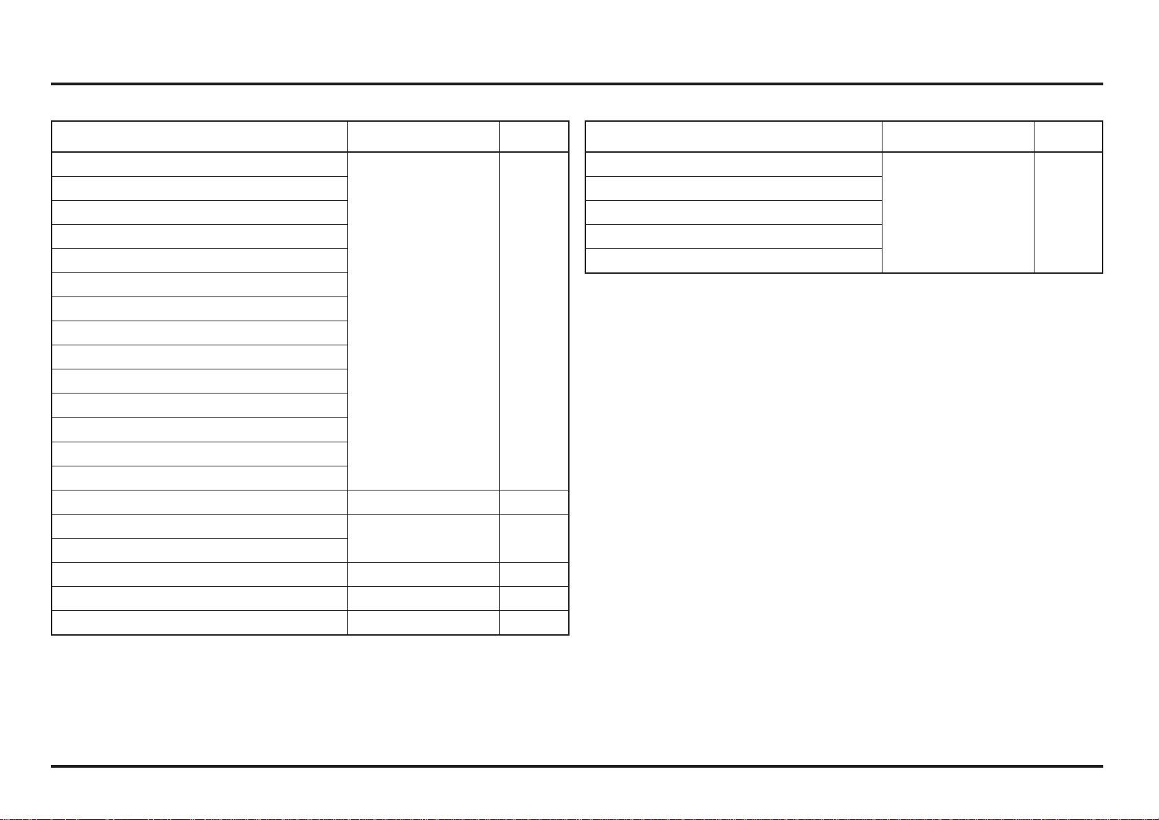
Unit: mm (in)
Item Standard Service Limit
Rear Suspension SHOWA
Shock absorber spring pre-load 126.5 (4.98) –
Spring free length 133 (5.2) 130.3 (5.13)
Nitrogen gas pressure 1.27 - 1.47 Mpa (13 - 15 kgf
/
cm
2
)–
Tension adjuster setting 10±2 clicks from full hard –
Brakes
Recommended brake fluid DOT 4 brake fluid –
Front Brake disc thickness
Brake disc runout
3.0 (0.12)
–
2.5 (0.10)
0.15 (0.006)
Rear Brake disc thickness
Brake disc runout
3.0 (0.12)
–
2.5 (0.10)
0.15 (0.006)
Electrical
Spark plug Standard: NGK: CR6EH-9 –
Spark plug gap 0.80 – 0.90 (0.031 – 0.035) –
Ignition coil resistance
Primary
Secondary with plug cap
Secondary without plug cap
2.6 -3.2 Ω (20º C)
17.3 -22.8 kΩ (20º C)
13.5 – 16.5 KΩ (20º C)
–
–
–
Ignition pulse generator
Resistance
85 -115 Ω (20º C)
–
Alternator
Regulated voltage
Charging coil resistance
ECT sensor resistance
13.5 – 14.5 V/1.800 min-1 (rpm)
0.7 -1.0 Ω (20º C)
2.3 -2.6 kΩ (20º C)
–
–
–
Bulbs
Headlight
Position light
Brake/tail light
Turn signal light
Speedometer
12V – 35/35 W
12V – 4 W
12V – 21/5 W
12V – 10 W X 4
12V
–
–
–
–
–
Service data
2-5
2-5
Engine
Item Q’ty
Thread
Dia. (mm)
Torque
N•m (kgf•m / lbf•ft)
Remarks
Transmission oil drain bolt 1 8 22 (2.2 / 16) Note 1
Engine oil drain bolt 1 8 22 (2.2 / 16) Note 1
Right crankcase cover joint pipe 1 18 18 (1.8 / 13) Note 2
Timing hole cap 1 14 7 (0.7 / 5.1) Note 3
Bearing set plate socket bolt 4 6 9.8 (1.0 / 7) Note 4
Bearing set plate screw 2 6 12 (1.2 / 9) Note 4
Bearing set plate flat screw 2 6 9.8 (1.0 / 7) Note 4
Cylinder head sealing bolt 1 12 32 (3.3 / 24) Note 4
Cylinder head mounting nut 2 9 39 (4.0 / 29) Note 1
Cylinder head joint pipe 1 18 18 (1.8 / 13) Note 2
Vacuum port joint 1 5 2.5 (0.25 / 1.8)
Primary drive gear special bolt 1 12 108 (11.0 / 80) Note 1
Flywheel nut 1 18 167 (17.0 / 123) Note 1
Cam chain tensioner bolt 1 6 12 (1.2 / 9) Note 4
Valve clearance adjusting nut 4 6 14 (1.4 / 10) Note 1
Injector holder socket bolt 2 6 9.8 (1.0 / 7)
Fuel hose banjo bolt (holder side) 1 18 24 (2.4 / 17.7)
Water pump impeller 1 7 12 (1.2 / 9)
Clutch oil bleeder screw 1 8 6 (0.6 / 4.3)
Clutch spring bolt 6 6 12 (1.2 / 9)
Clutch center lock nut 1 18 69 (7.0 / 51) Note 1
Drive sprocket UBS bolt 1 8 31 (3.2 / 23)
Shift drum center special bolt 1 8 22 (2.2 / 16) Note 4
Shift drum stopper arm bolt 1 6 12 (1.2 / 9)
Shift return spring pin 1 8 22 (2.2 / 16)
Ignition pulse generator bolt 2 5 5.4 (0.55 / 4.0) Note 4
Stator mounting bolt 3 5 5.4 (0.55 / 4.0) Note 4
Spark plug 1 10 16 (1.6 / 12) Note 2
Notes: 1. Apply clean engine oil to the threads and seating surface.
2. Apply sealant to the threads.
3. Apply grease to the threads.
4. Apply a locking agent to the threads.
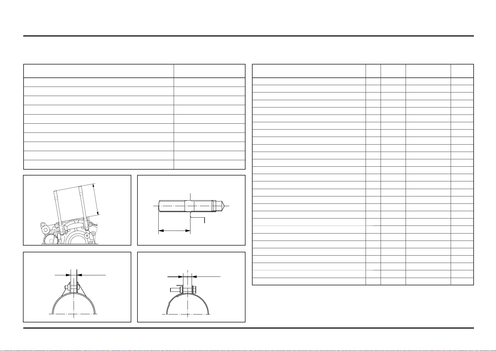
Cylinder stud bolt:
Insulator band (cylinder head side):
Exhaust pipe stud bolt:
Insulator band (throttle body side):
101,5±1mm
17±0,5mm
7±1mm
7±1mm
Torque Values
Standard
Item
Torque
N•m (kgf•m / Ibf•ft)
5 mm bolt and nut 5 (0.52 / 3.5)
6 mm bolt and nut 10 (1.0 / 7)
8 mm bolt and nut 22 (2.2 / 16)
10 mm bolt and nut 33 (3.4 / 25)
12 mm bolt and nut 53 (5.4 / 40)
5 mm screw 4 (0.42 / 3)
6 mm screw and flange bolt (SH type) 9 (0.9 / 7)
6 mm flange bolt and nut 12 (1.2 / 9)
8 mm flange bolt and nut 26 (2.7 / 20)
10 mm flange bolt and nut 38 (3.9 / 29)
Service data
2-6
2-6
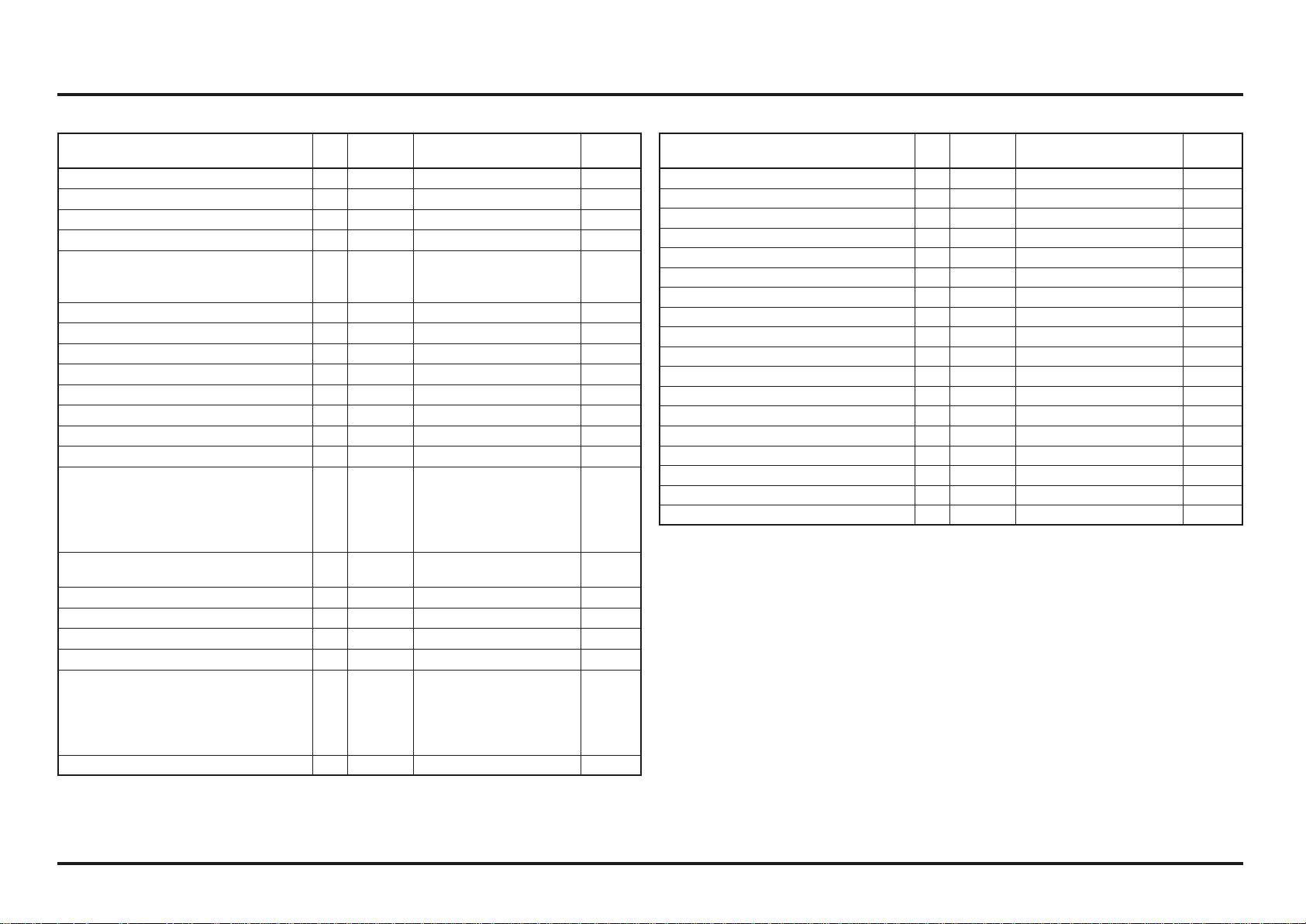
Frame
Item Q’ty
Thread
Dia. (mm)
Torque
N•m (kgf•m. Ibf•ft)
Remarks
Steering head top thread 1 26 5 (0.5 / 3.6) Note 1
Steering stem nut
1 20 99 (9.9 / 73)
Note 1
Clutch hose (master cylinder)
1 10 14 (1.4 / 10.3)
Clutch hose (secondary cylinder)
1 10 26 (2.7 / 20)
Rear master cylinder mounting bolt
2 6 9 (0.8 / 6.6)
ECT sensor
1 12 23 (2.3 / 17)
Fuel hose banjo bolt
1 12 22 (2.2 / 16)
Fuel pump mounting bolt
7 5 8 (0.8 / 5.9)
Front spoke nipple
32 BC 3.5 3.7 (0.38 / 2.8)
Rear spoke nipple
32 4 2.5 (0.26 / 1.9)
Shock absorber spring lock nut
1 50 49 (5.0 / 36)
Shock arm bolt/nut
1 10 39 (4.0 / 29)
Shock link bolt/nut
2 10 39 (4.0 / 29)
Rim lock nut
1 8 13 (1.3 / 9)
Fork cap
2 36 13 (1.3 / 9)
Right fork adjuster case lock nut
1 10 15 (1.5 / 11)
Right fork lower bolt
1 14 25 (2.6 / 18.4)
Left fork lower bolt
1 14 25 (2.6 / 18.4)
Notes: 1. Apply grease to the sliding surface.
2. Apply a locking agent to the threads.
Frame
Item Q’ty
Thread
Dia. (mm)
Torque
N•m (kgf•m. Ibf•ft)
Remarks
Handlebar holder bolt
4 8 22 (2.2 / 16)
Note 1
Front axle
1 17 69 (7.0 / 51)
Note 1
Rear axle nut
1 17 69 (7.0 / 51)
Note 1
Final driven sprocket nut
4 8 32.5 (3.3 / 23.9)
Shock absorber:
Upper mounting bolt/nut
Lower mounting bolt/nut
1
1
10
10
39 (4.0 / 29)
39 (4.0 / 29)
Fork top pinch bolt
2 8 21 (2.1 / 15.4)
Note 1
Fork bottom pinch bolt
4 8 21 (2.1 / 15.4)
Note 1
Swingarm pivot nut
1 14 69 (7.0 / 51)
Note 1
Front brake disc mounting bolt
46
19 (1.9 / 14) Note 2
Rear brake disc mounting bolt
46
17 (1.7 / 12.5) Note 2
Side stand pivot nut
1 10 23 (2.3 / 17)
Side stand bracket mounting bolt
2 8 27 (2.8 / 20)
Note 2
Exhaust pipe flange nut
2 6 12 (1.2 / 9)
Engine hanger:
Upper hanger bolt/nut
Front hanger bolt
Down tube mounting bolt
Rear lower bolt
2
1
4
1
8
10
8
10
24 (2.4 / 17)
50 (5.1 / 37)
26 (2.7 / 19)
39 (4.0 / 29)
Note 1
Note 1
Note 1
Skid plate:
Front mounting bolt
4
8
27 (2.8 / 20)
Throttle housing bolt
2 5 4.2 (0.43 / 3.1)
Clutch lever holder bolt
2 5 5.5 (0.56 / 4)
Front brake master cylinder holder bolt
2 5 5.5 (0.56 / 4)
Front brake caliper mounting bolt
2 8 27 (2.8 / 20)
Note 2
Brake hose:
Front master cylinder
Front caliper
Rear master cylinder
Rear brake caliper
1
1
1
1
10
8
10
10
14 (1.4 / 10.3)
20 (2.0 / 14)
26 (2.7 / 19)
26 (2.7 / 19)
Brake pedal pivot bolt 1 8 29 (3.0 / 22) Note 2
Service data
2-7
2-7
Tools
Special
Common
Description Tool number Applicability
Bearing remover. 12 mm
Remover shaft
Remover weight
Generic tool
07936–1660120
07741–0010201
Water pump bearing
Water seal driver 07945–KA30000 Water seal
Attachment. 28 x 30 mm 07946–1870100 Water pump bearing
Clutch center holder 07JMB–MN50302 Clutch center lock nut
Fork seal driver set 07947–4630100 Fork oil seal
Fork damper holder 89515–NN3–821 Right fork socket bolt
Fork damper holder 07930–KA50100 Left fork socket bolt
Ball race remover 07948–4630100 Stem bearing race
Steering stem driver Generic tool Stem lower bearing
Bearing driver 07946–KA50000 Swingarm pivot bearing
Bearing remover 07946–MJ00100 Shock link needle bearing
Swingarm link bearing
Spherical bearing driver 07HMF–KS60100 Shock absorber bearing
Snap ring pliers 07914-SA50001 Master cylinder snap ring
Flywheel holder 89020–NN4–003 Flywheel
Flywheel puller Generic tool Flywheel
Compressor attachment 07959–MB10000 Shock absorber spring
PGM-FI warning unit assembly 38890-NN4-306 PGM-FI Self-diagnosis system
Test probe 07ZAJ-RDJA110 PGM-FI Self-diagnosis system
Diagnostic tool adapter 070MZ-K530101 PGM-FI Self-diagnosis system
Diagnostic tool (DST) Generic tool PGM-FI Self-diagnosis system
Description Tool number Applicability
Spoke nipple wrench 07701–0020300 Front spoke nipple
Gear holder 07724–0010100 Primary drive gear bolt
Bearing remover head 07746–0050600 Wheel bearing
Bearing remover shaft 07746–0050100 Wheel bearing
Driver 07749–0010000 Bearing removal/installation
Attachment. 24 x 26 mm 07746–0010700 Swingarm pivot bearing
Attachment. 32 x 35 mm 07746–0010100 Right countershaft bearing
Left mainshaft bearing
Attachment. 37 x 40 mm 07746–0010200 Left shift drum bearing
Attachment. 42 x 47 mm 07746–0010300 Right mainshaft bearing
Left countershaft bearing
Right shift drum bearing
Wheel bearing
Ball race
Attachment. 52 x 55 mm 07746–0010400 Crankshaft oil seal
Attachment. 62 x 68 mm 07746–0010500 Left crankshaft bearing
Attachment. 72 x 75 mm 07746–0010600 Right crankshaft bearing
Pilot. 12 mm 07746–0040200 Water pump bearing
Pilot. 17 mm 07746–0040400 Right countershaft bearing
Left mainshaft bearing
Pilot. 20 mm 07746–0040500 Left countershaft bearing
Wheel bearing
Swingarm pivot bearing
Pilot. 22 mm 07746–0041000 Right mainshaft bearing
Pilot. 25 mm 07746–0040600 Right shift drum bearing
Pilot. 30 mm 07746–0040700 Right crankshaft bearing
Pin spanner 07702–0020001 Shock spring adjuster (2 required)
Shock absorber compressor 07GME–0010100 Shock absorber spring
Service data
2-8
2-8
Lubrication & Seal Points
Engine
Item Material Remarks
Crankcase sealing bolt threads and seating surface Repsol 4T-stroke engine oil
Cylinder bore inner surface
Cylinder head nut threads and seating surface
Piston inner area, piston pin area
Piston pin outer surface
Piston ring surface
Crankshaft oil seal lips
Decompressor weight sliding surface
Valve adjusting nut threads
Oil pump rotor sliding surface
Clutch outer sliding surface
Clutch friction disc surface
Clutch center nut threads and seating surface
Clutch lifter piece needle bearing area
Primary drive gear bolt threads and seating surface
Shift drum grooves
Gearshift spindle serration
Flywheel nut threads and seating surface
Each bearing
Each O-ring
Crankcase inside (transmission oil) REPSOL MOTO TRANSMISSION
(75W)
ELF HTX740 (75W)
570 cm
3
Crankcase inside (engine oil) Repsol 4T-stroke engine oil
10W-30 or equivalent
600 cm
3
Item Material Remarks
Connecting rod small end I.D. Molybdenum oil solution
(A 50/50 mixture of
molybdenum disulfide
grease and engine oil
Connecting rod big end
Camshaft outer surface
Rocker arm I.D.
Valve stem sliding surface
Valve stem end sliding surface
Clutch outer collar sliding surface
Mainshaft spline and gear sliding surface
Countershaft spline and gear sliding surface
Shift fork I.D. and gear contact area
Shift fork shaft surface
Kickstarter spindle spline area and gear sliding
surface
Each gear
Right crankshaft bearing set plate bolt threads Locking agent 6.5 ± 1 mm
Right mainshaft bearing/shift drum bearing set plate
bolt threads
Left coutershaft bearing set plate bolt threads 3.5 ± 1 mm
Left crankcase sealing bolt threads
Cylinder mounting bolt threads
Cylinder head sealing bolt threads 6.5 ± 1 mm
Cam chain tensioner bolt threads
Shift drum center bolt threads
Ignition pulse generator bolt threads
Stator mounting bolt threads

Service data
2-9
2-9
Item Material Remarks
Clutch slave cylinder piston/O-ring Silicone grease
Left crankcase cover cap threads Lithium based multipurpose
grease
Each oil seal lips
Water seal lips
Right crankcase and cylinder head cover water hose
joint thread
Sealant
Cylinder head cover mating surface Three Bond 1207B or
equivalent
Cam chain tensioner bolt
Application zone
6.5±1 mm 3 - 4 mm
Left crankcase drain hole #225
Application zone
2.5±1 mm 1.2±0.4 mm
Left crankcase drain hole #225
Service data
2-10
2-10
Frame
Item Material Remarks
Steering head bearing race and bearings
Multi-purpose grease
Steering head dust seal lips
Swingarm pivot needle bearing
Swingarm pivot dust seal lips
Shock link/shock arm needle bearings
Shock link/shock arm dust seal lips
Kickstarter arm joint sliding
Brake lever pivot sliding surface
Side stand pivot sliding surface
Brake pedal pivot sliding surface
Chain tensioner roller bearings
Clutch lever pivot sliding surface
Front and rear wheel axle thread
Step joint pin surface
Throttle pipe sliding surface and throttle wire drum 4-stroke engine oil
Brake hydraulic system inside DOT 4 brake fluid
Clutch hydraulic system inside
Air cleaner element Specific oil for air filters
Throttle cable sliding surface Cable lubricant
Handlebar grip Honda bond A or equivalent
Item Material Remarks
Drive chain adjuster stopper screws threads
Locking agent
Side stand bracket bolt threads
Drive chain slider mounting screw threads
Rear brake hose clamp screw threads
Cooling fan screws threads
Service data
2-11
2-11
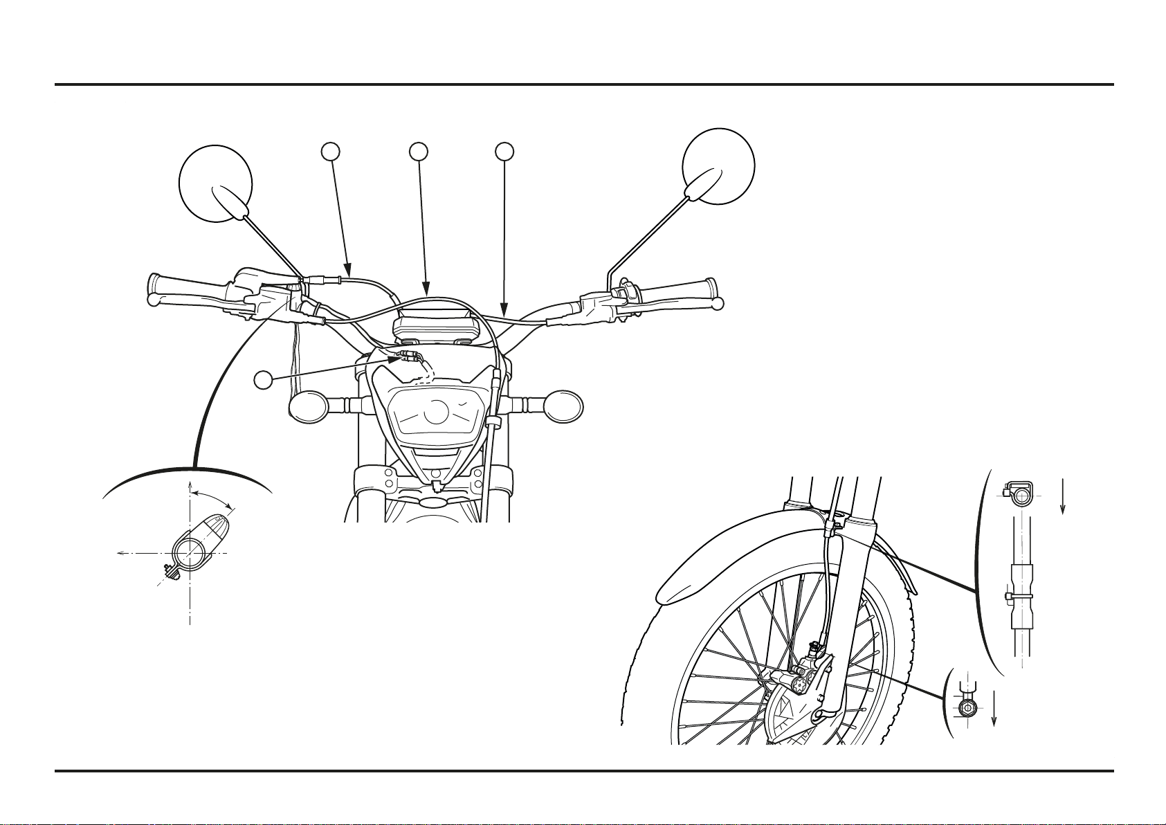
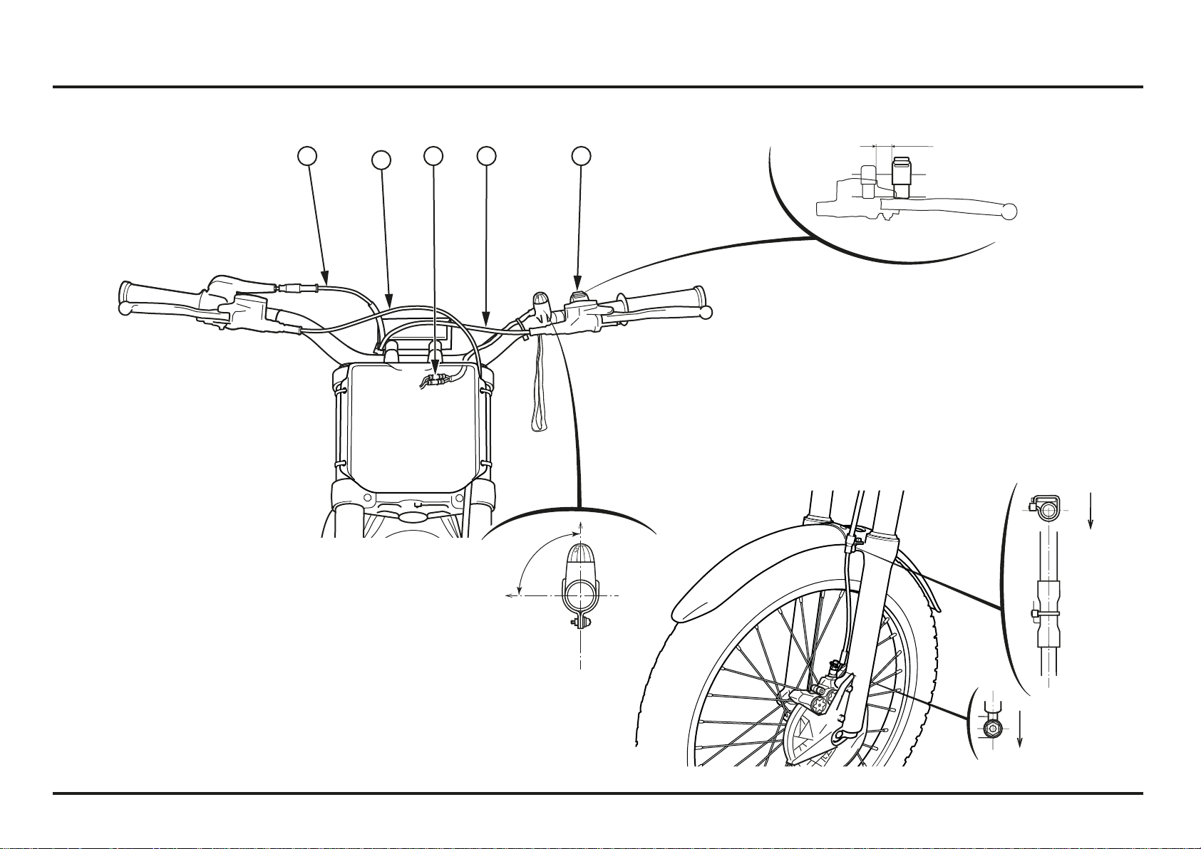
Cable & Harness Routing (2ED)
(1) FRONT BRAKE HOSE
(2) THROTTLE CABLE
(3) CLUTCH HOSE
(4) MAGNETIC STOP SWITCH CONNECTOR
45º
2 1
4
3
FRONT
FRONT
Service data
2-12
2-12
Cable & Harness Routing (4ED)
(1) FRONT BRAKE HOSE
(2) THROTTLE CABLE
(3) CLUTCH HOSE
(4) MAGNETIC STOP SWITCH CONNECTOR
(5) MAPPING SWITCH
FRONT
FRONT
15 mm
5
90º
2
1
3
4
Service data
2-13
2-13
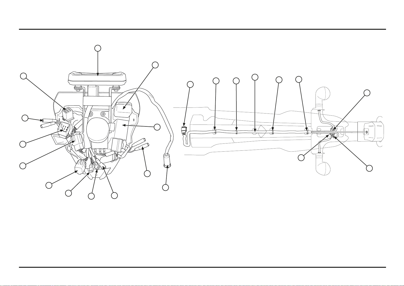
Cable & Harness Routing (2ED)
(1) SPEEDOMETER
(2) POWER RELAY
(3) WINKER RELAY
(4) 4P CONNECTOR OBD
(5) RIGHT FRONT TURN SIGNAL CONNECTORS
(6) LEFT FRONT TURN SIGNAL CONNECTORS
(7) 9P CONNECTOR SUB-INSTALLATION
(8) 6P CONNECTOR SPEEDOMETER
(9) 3P CONNECTOR SPEED SENSOR
(10) 4P CONNECTOR MIL
(11) FRONT STOP SWITCH CONNECTOR
(12) 2P CONNECTOR (INACTIVE)
(13) 9P CONNECTOR LIGHTING SWITCH
(14) INDICATOR LIGHT INSTALLATION
(15) INDICATOR LIGHT INSTALLATION CONNECTOR
(16) RIGHT REAR TURN SIGNAL CONNECTORS
(17) LEFT REAR TURN SIGNAL CONNECTORS
(18) CLAMPS
9
8
7
6
5
4
3
2
1
15
12
18
18
11
10
13
14
18
18
17
16
18
Service data
2-14
2-14
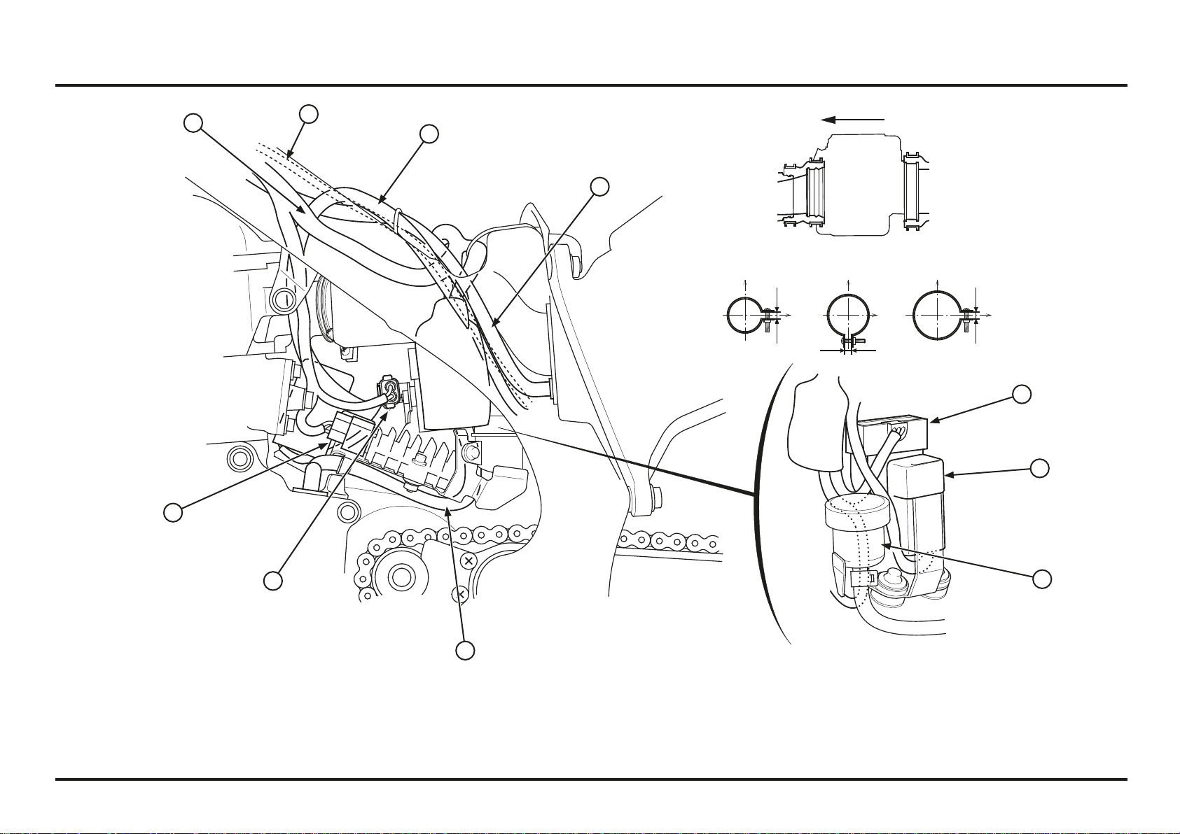
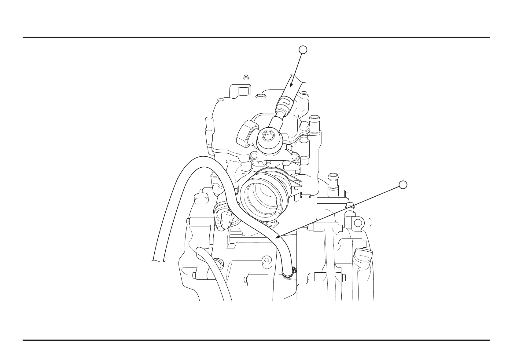
Cable & Harness Routing
(1) MAIN WIRE HARNESS
(2) FUEL PUMP WIRE
(3) CYLINDER HEAD BREATHER HOSE
(4) AIR FILTER BOX BREATHER HOSE
(5) STORAGE TANK
(6) ENGINE STOP SWITCH WIRE
(7) FAN MOTOR WIRE
(8) FUEL CAP BREATHER HOSE
(9) SPARK PLUG WIRE
(10) WIRE HARNESS (TO IGNITION COIL)
(11) ECT SENSOR
(12) FUEL TANK BREATHER HOSE (2ED)
(13) HOSE CONNECTOR (2ED)
UPPER
RH
20-30º
13
1
8
2
3
4
5
6
7
8
9
10
11
12
Service data
2-15
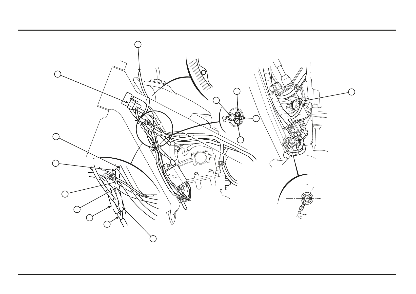
2-15
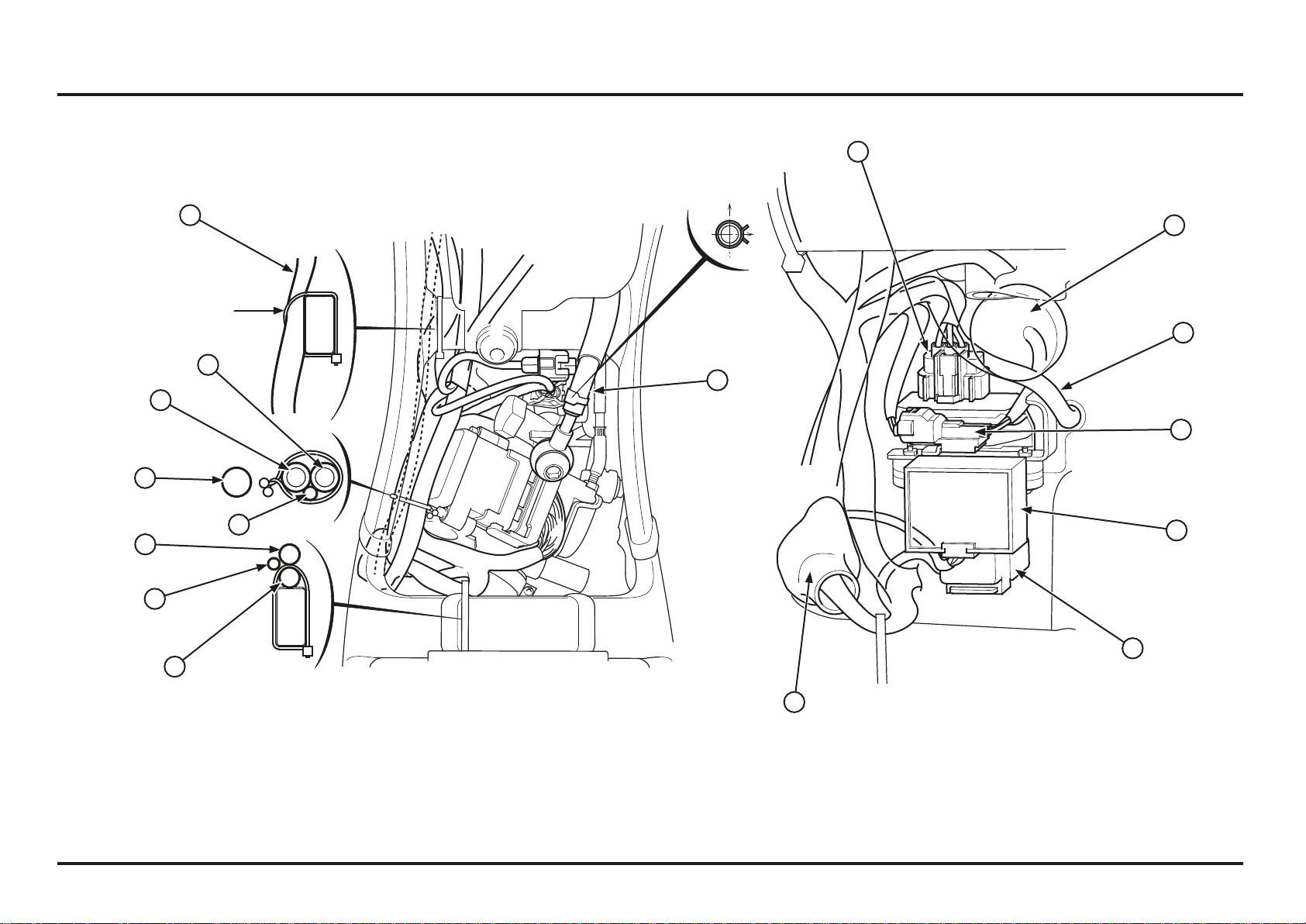
(1) WIRE HARNESS
(2) THROTTLE CABLE
(3) CLUTCH HOSE
(4) CONNECTORS BOOT
– FAN MOTOR 2P CONNECTOR
– POWER / MAPPING 4P CONNECTOR
– COOLANT TEMPERATURE 2P CONNECTOR (2ED)
(5) UPPER RADIATOR HOSE
(6) SPARK PLUG WIRE
(7) FAN MOTOR WIRE
(8) FILTER BOX BREATHER HOSE
(9) CYLINDER HEAD BREATHER HOSE
(10) SPEED SENSOR CABLE (2ED)
Clamp at white tape
1
2
3
4 5 6
7
8
9
10
Service data
2-16
2-16
(1) THROTTLE CABLE
(2) CLUTCH HOSE
(3) FUEL TANK BREATHER HOSE
1
2
3
2
3
1
45º
FR
FR
UPPER
UPPER
FR
RH
RH
RH
RH
RH
Service data
2-17
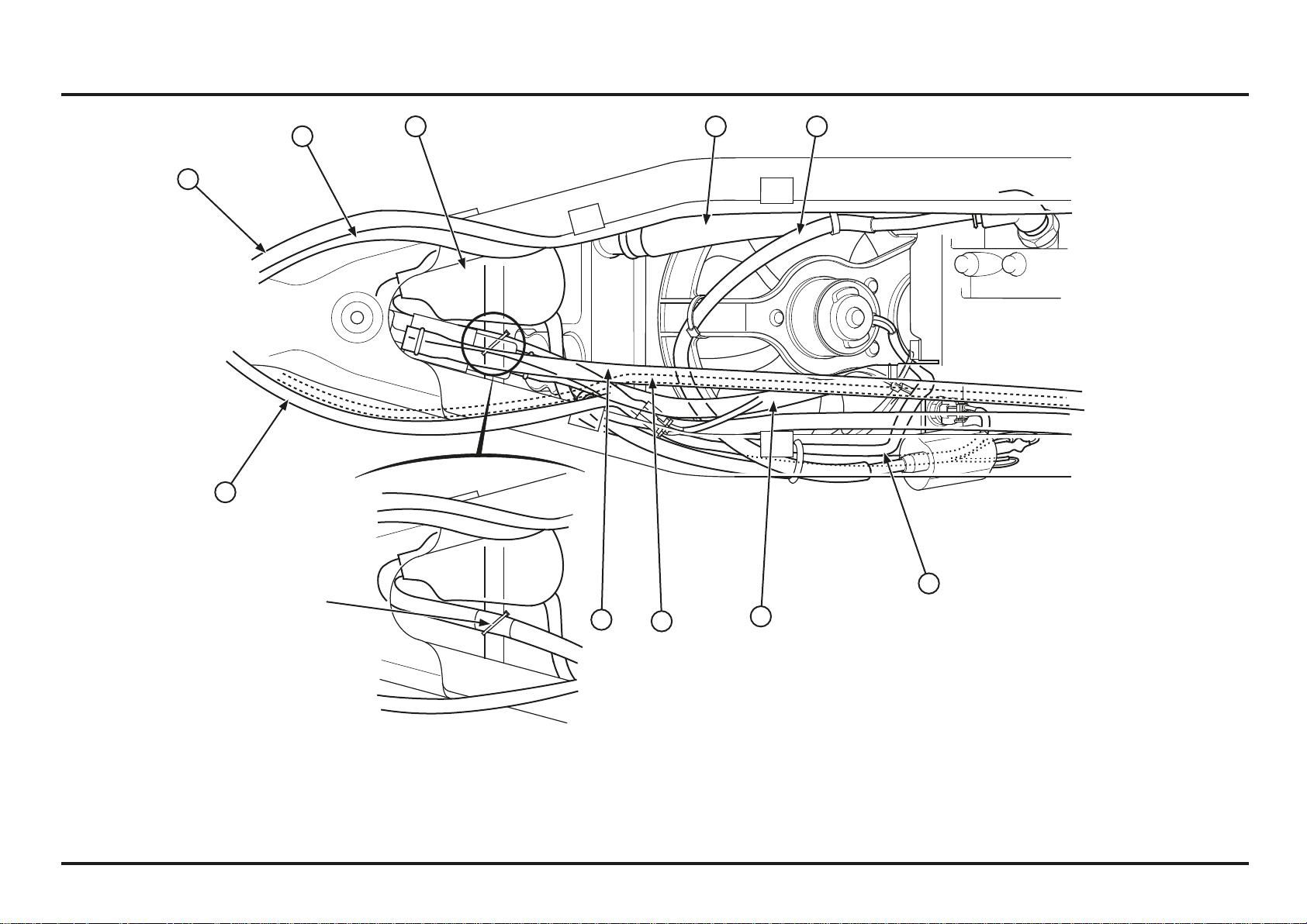
2-17
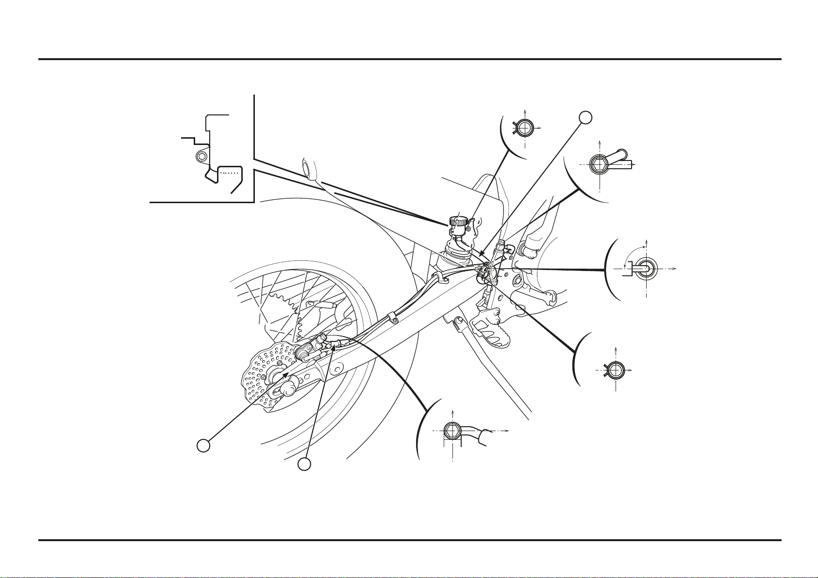
(1) MAIN WIRE HARNESS
(2) TRANSMISSION BREATHER HOSE
(3) FILTER BOX BREATHER HOSE
(4) ALTERNATOR WIRE
(5) CONDENSER 2P (BLACK) CONNECTOR
(6) REGULATOR/RECTIFIER 5P (BLACK) CONNECTOR
(7) BANK ANGLE SENSOR
(8) FAN MOTOR RELAY
(9) REAR BRAKE RESERVOIR TANK
(10) SPEED SENSOR CABLE (2ED)
RH
FR
RHRH
UPPER UPPER UPPER
10
1
2
3
4
5
6
7
8
9
Service data
2-18
2-18
(1) MAIN WIRE HARNESS (TO CONNECTOR COVER)
(2) MAIN WIRE HARNESS (TO RELAY)
(3) MAIN WIRE HARNESS (TO ECU)
(4) AIR FILTER BOX BREATHER HOSE
(5) TRANSMISSION BREAHTER HOSE
(6) WIRE HARNESS
(7) FUEL FEED HOSE
(8) REGULATOR/RECTIFIER 5P (BLACK) CONNECTOR
(9) CONDENSOR
(10) CONDENSOR 2P (BLACK) CONNECTOR
(11) BANK ANGLE SENSOR
(12) FAN MOTOR RELAY
(13) CONNECTOR COVER
(14) SPEED SENSOR CABLE (2ED)
Clamp at white tape
1
2
3
4
5
5
6
7
8
9
10
11
12
13
6
14
Service data
2-19
2-19
(1) REAR BRAKE HOSE
(2) REAR BRAKE RESERVOIR HOSE
(3) SPEED SENSOR (2ED)
90º
UPPER
UPPER
RH
FR
FR
RH
1
2
3
Service data
2-20
2-20
(1) FUEL FEED HOSE
(2) TRANSMISSION BREATHER HOSE
1
2
3-1
3-1
Pre-ride Inspection
For your safety, it is very important to take a few moments
before each ride to walk around your COTA 301RR and
check its condition.
!
WARNING
Improperly maintaining this COTA 301RR or failing to
correct a problem before riding can cause a crash in
which you can be seriously hurt or killed.
Always perform a Pre-ride and Pre-race inspection be-
fore every ride and correct any problems.
Check the following items before you get on the Cota
301RR:
Fuel, oil and water leaks
Coolant for proper level
Spark plug for proper heat range, carbon fouling and
spark plug cap terminals for looseness
Clutch operation
Steering head bearings and related parts for condition
Damaged or distorted frame
Throttle grip and throttle valve operation
Tires for damaged or improper inflation pressure
Front and rear suspension for proper operation
Front and rear brakes, for proper operation
Drive chain for correct slack and adequate lubrication
Drive chain slider and roller for damage or wear
Loose bolts, screws and other fasteners
3. Service and maintenance
Maintenance schedule
Perform pre-ride Inspection at each scheduled maintenance period.
I: Inspect and clean, Adjust, Lubricate or Replacement if necessary. C: Clean, R: Replace, L: Lubricate.
Item
Frequency
Each race or
about 2,5 h.
Every 6
races or
about 15 h.
Every
half a
year
Every
year
Remarks
Fuel Line I
Fuel Filter I
Clean Under The Front Suspension Fender I
Throttle Operation I
Air Cleaner C Check the air cleaner after riding in dusty area
Spark Plug I R
Valve Clearance I I: After the first brake-in period
Engine Oil I R R: After the first brake-in period
Engine Oil Filter R R: After the first brake-in period
Engine Oil Strainer Screen I
Engine Idle Speed I
Transmission Oil R
Radiator Coolant I R
Cooling System I R
Piston I R
Piston Ring I R
Drive Chain I, L
Drive Chain Slider/Tensioner I
Drive/Driven Sprocket I
Brake Fluid I R
Brake Pad Wear I
Brake System I
Clutch Fluid I
Clutch System I
Control Cables I, L
Exhaust Pipe/Muffler I C
Suspension I C Check the spherical bearing damage.
Shock absorber (nitrogen pressure) I
Swingarm/Shock Linkage I C
Fork Oil I R
Wheels/Tires I
Steering Head Bearing I
Nuts, Bolts, Fasteners I
Service and maintenance
3-2
3-2
Replacement Parts
Parts Requiring Periodic Replacement
Item Replacement Interval Cause
Engine
Spark plug/plug cap Every 6 races Contamination or emulsification
Engine oil Every 6 races
Engine oil filter Every 6 races
Transmission oil Every 6 races
Piston Every year Damage or wear at skirt
Piston ring Every half a year Damage at ends or wear
Radiator coolant Every year
Frame
Front fork fluid Every half a year
Fast wearing/expendable parts
Item Cause
Engine
Clutch disc Wear or discoloration
Clutch spring Fatigue
Drive sprocket Wear or damage
Frame
Front/rear tire Wear
Brake pad Wear
Chain slider Wear
Driven sprocket Wear or damage
Drive chain Elongation or wear
Warming-up Inspection
When warming-up the engine, check for the following:
Do not rev the engine more than necessary or engine
damage may result.
Check for fuel, oil and water leaks
Warm up the engine for a few minutes until it is heated
to the operating temperature until the engine responds
to the throttle smoothly.
Ride Inspection
When running the Cota, check for the following:
Control system
Brake stopping power
After Ride Inspection
After riding the Cota, check for the following:
Color condition of piston head and spark plug
Signs of detonation
Fuel, oil and water leaks
Loose or missing bolts and nuts
Service and maintenance
3-3
3-3
Remove the flame trap from the air cleaner element.
Check the frame trap for damage, replace if necessary.
Thoroughly wash the element in clean non-flammable
cleaning solvent, then wash in a solution of hot water
and dish-washing liquid soap.
Apply specific oil for air filters to the element, and squeeze
out excess oil.
Clean the inside of the air cleaner housing.
!
WARNING
Never use gasoline or low flash point solvents for clea-
ning the air cleaner element. A fire or explosion could
result.
Soak the element in engine oil and squeeze out the
excess.
NOTICE
Do not twist the element to squeeze out the excess.
Failure to follow this precaution can result in a damaged
element.
Installation is in the reverse order of removal.
(1) FLAME TRAP
(2) AIR CLEANER ELEMENT
(1) AIR CLEANER ELEMENT
Air Cleaner
Remove the rear fender.
Remove the four bolts and air cleaner housing cover.
Remove the air cleaner element assembly from the air
cleaner housing.
(1) BOLTS
(2) AIR CLEANER HOUSING COVER
Fuel Line
Remove the rear fender.
Check the fuel feed hose for cracks, deterioration or
leakage.
(1) FUEL FEED HOSE
1
2
1
2
1
1
Service and maintenance
3-4
3-4
(1) TIMING HOLE CAP/O-RING
Valve Clearance
Inspection
Inspect and adjust the valve clearance while the engine is
cold (below 35˚C/95˚F).
Remove the fuel tank/injector assembly.
Remove the bolts and tappet adjusting hole covers from
the cylinder head cover.
Remove the timing hole cap and O-ring.
(1) BOLTS
(2) TAPPET ADJUSTING HOLE COVER
(1) SPARK PLUG GAP
Flash Over
If engine misfire occurs due to arcing, replace both the
spark plug and the cap.
Spark Plug Cap
Remove the spark plug cap from the spark plug.
Clean the inside of the plug cap with electrical contact
cleaner to prevent misfire.
(1) INSULATOR
Spark Plug
Using a spark plug with the wrong heat range can damage
the engine or cause the plugs to foul. Be careful to select
the correct spark plug for the conditions.
Standard plug: NGK: CR6EH-9
Plug Gap
Remove the spark plug and measure the spark plug gap.
Standard: 0.8 – 0.9 mm (0.031 – 0.035 in)
Replace the spark plug if the spark plug gap is out of
specification.
Install and tighten the spark plug.
Torque: 16 N•m (1.6 kgf•m, 12 lbf•ft)
(1) SPARK PLUG CAP
(2) SPARK PLUG
1
1
1
1
1
2
2
1
Service and maintenance
3-5
3-5
(1) O-RING
(2) TIMING HOLE CAP
Check that the valve adjusting hole cover O-ring is in good
condition, replace if necessary.
Coat the O-rings with clean engine oil and install them in
the valve adjusting hole cover grooves.
Install the valve adjusting hole cover with their “UP” mark
facing up and then install and tighten the bolts securely.
Check the timing hole cap O-ring is in good condition,
replace if necessary.
Install and tighten the timing hole cap.
(1) O-RING
(2) VALVE ADJUSTING HOLE COVER
(3) “UP” MARK (4) BOLTS
Insert a feeler gauge between the rocker arm and
valve stem and measure the intake and exhaust valve
clearances.
Valve clearance:
Intake: 0.12 ± 0.03 mm (0.005 ± 0.001 in)
Exhaust: 0.30 ± 0.03 mm (0.012 ± 0.001 in)
Adjust by loosening the lock nut and turning the adjusting
screw until there is a slight drag on a feeler gauge.
Tools:
Valve adjusting wrench, 10x12 mm 07708-0030200
(equivalent commercially available)
Valve adjuster B 07708–0030400
After adjustment, tighten the lock nut while holding the
adjusting screw.
Recheck the valve clearance.
Torque: 14 N•m (1.4 kgf•m, 10.3 lbf•ft)
(1) FEELER GAUGE
Operate the kickstarter pedal and align the “T” mark on
the flywheel with the index mark on the left crankcase
cover.
Make sure the piston is at TDC (Top Dead Center) on the
compression stroke by moving the rocker arms.
(1) “T” MARK
(2) INDEX MARK
2
1
1
44
3
2
1
2
1
Service and maintenance
3-6
3-6
(1) OIL FILTER COVER
(2) O-RINGS
(3) OIL FILTER
(4) SPRING
Oil Filter Change
Remove the left crankcase cover (page 4-49).
Remove the oil filter cover retaining plate bolt and plate.
Remove the oil filter cover and O-rings.
Remove the oil filter and spring.
(1) BOLT
(2) RETAINING PLATE
Oil Change
Change the engine oil with the engine warm.
Support the motorcycle with it side stand.
Remove the bolts and skid plate.
1. Remove the oil filler cap/dipstick.
2. Place an oil drain pan under the engine and remove the
drain bolt on the left crankcase cover.
3. After the oil has completely drained, make sure that
the sealing washer is in good condition and reinstall
the drain bolt. Tighten the drain bolt to the specified
torque.
Torque: 22 N•m (2.2 kgf•m, 16 lbf•ft)
4. Pour recommended engine oil slowly through the oil
filler hole.
Specified engine oil:
Repsol 4-stroke motorcycle oil (SAE: 10W-30) or
equivalent
Capacity: 0.41 liter (0.43 US qt, 0.36 Imp qt) after draining
0.44 liter (0.46 US qt, 0.39 Imp qt) after oil filter
change
0.60 liter (0.63 US qt, 0.53 Imp qt) after
disassembly
Install the oil filler cap/dipstick.
(1) OIL FILLER CAP/DIPSTICK
(2) DRAIN BOLT/SEALING WASHER
(1) OIL FILLER CAP/DIPSTICK
(2) UPPER LEVEL LINE
(3) LOWER LEVEL LINE
Engine Oil/Oil Filter
Oil Level Inspection
Start the engine and let it idle for a 3 minutes.
Stop the engine and wait 3 minutes.
Support the motorcycle upright on a level surface.
Remove the oil filler cap/dipstick on left crankcase and
wipe the oil with a clean cloth.
Insert the dipstick without screwing it in, remove it and
check the oil level.
If the oil level is below or near the lower level line on the
dipstick, add the recommended engine oil to the upper
level line through the oil filler hole.
Specified engine oil:
Repsol 4-stroke motorcycle oil (SAE: 10W-30) or
equivalent
3
2
1
2
1
4
3
2
2
1
2
1
Service and maintenance
3-7
3-7
Oil Strainer Screen Cleaning
Remove the oil strainer screen from the left crankcase
groove.
Clean the strainer.
Reinstall the oil strainer screen.
Note the direction of the screen.
Install the left crankcase cover being careful not to
damage the O-ring and oil seal.
(1) OIL STRAINER SCREEN
(1) RETAINING PLATE
(2) BOLT
Install new O-rings into the oil filter cover grooves.
Install the oil filter cover into the left crankcase while
aligning the cover flange with the oil filter groove.
Make sure that the oil filter cover seats properly in the
crankcase.
Install the retaining plate and tighten the bolt securely.
(1) NEW O-RINGS
(2) OIL FILTER COVER
(1) OIL FILTER
(2) “OUT SIDE” MARK
Apply grease to the oil filter spring end (filter side).
Install the spring into the new oil filter.
Install the new oil filter into the left crankcase with its
“OUT SIDE” mark facing out.
Installing the oil filter backwards will result in severe
engine damage.
(1) SPRING
(2) OIL FILTER
(3) APPLY GREASE
3
2
1
2
1
1
1
2
1
2
1
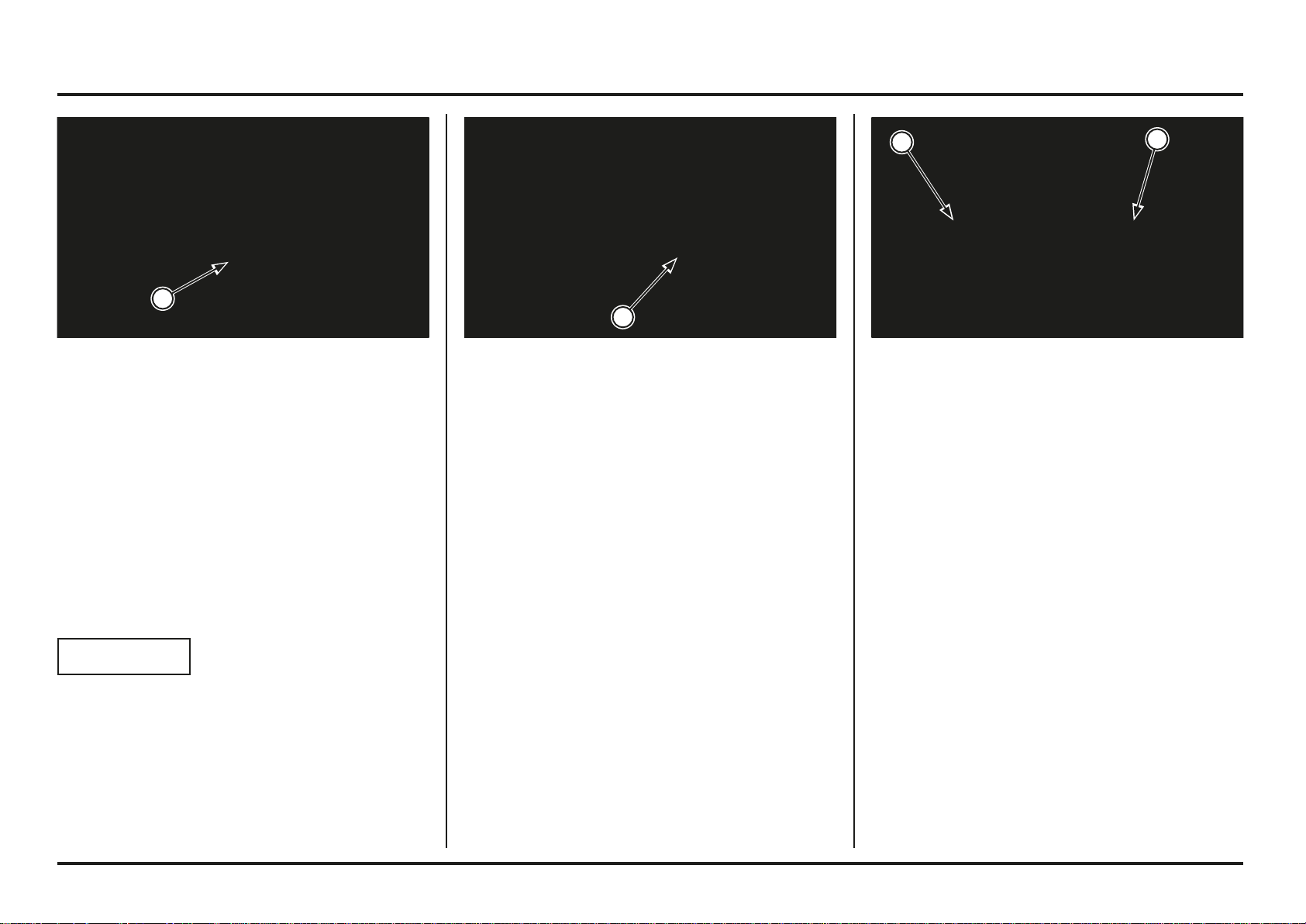
Service and maintenance
3-8
3-8
5. Pour specified transmission oil.
Specified transmission oil:
– REPSOL MOTO TRANSMISSION (75W)
– ELF HTX740 (75W)
Capacity: 0.54 liter (0.57 US qt, 0.48 Imp qt) after draining
0.57 liter (0.60 US qt, 0.50 Imp qt) after
disassembly
Check the O-ring is in good condition, install the oil filler
cap.
(1) FILLER CAP
(2) O-RING
Transmission Oil
Oil Change
Transmission oil should be changed at least every six
competitions to ensure consistent performance and
maximum service life of both transmission and clutch
components.
Warm-up the engine before draining the oil. This will
ensure complete and rapid draining.
Remove the bolts and skid plate.
1. Support the motorcycle in an upright position on level
surface.
2. Remove the oil filler cap from the clutch cover.
3. Place an oil drain pan under the engine to catch the oil,
then remove the drain bolt and sealing washer from the
left crankcase.
4. After the oil has drained completely, install the drain
bolt with a new sealing washer. Tighten the drain bolt
to the specified torque.
Torque: 22 N•m (2.2 kgf•m, 16 lbf•ft)
(1) DRAIN BOLT
Engine Idle Speed
Inspect and adjust the idle speed after all other engine
adjustments are within specification.
The engine must be warm for an accurate idle inspection
and adjustment.
Warm up the engine until the fan starts, shift the
transmission into neutral, and hold the motorcycle upright
position.
Connect a tachometer according to its manufacturer’s
operating instruction.
Idle speed: 1,800 ± 100 min-1 (rpm)
NOTICE
A low idling speed may cause starting problems.
(1) IDLE SPEED ADJUSTMENT SCREW
2
1
1
1
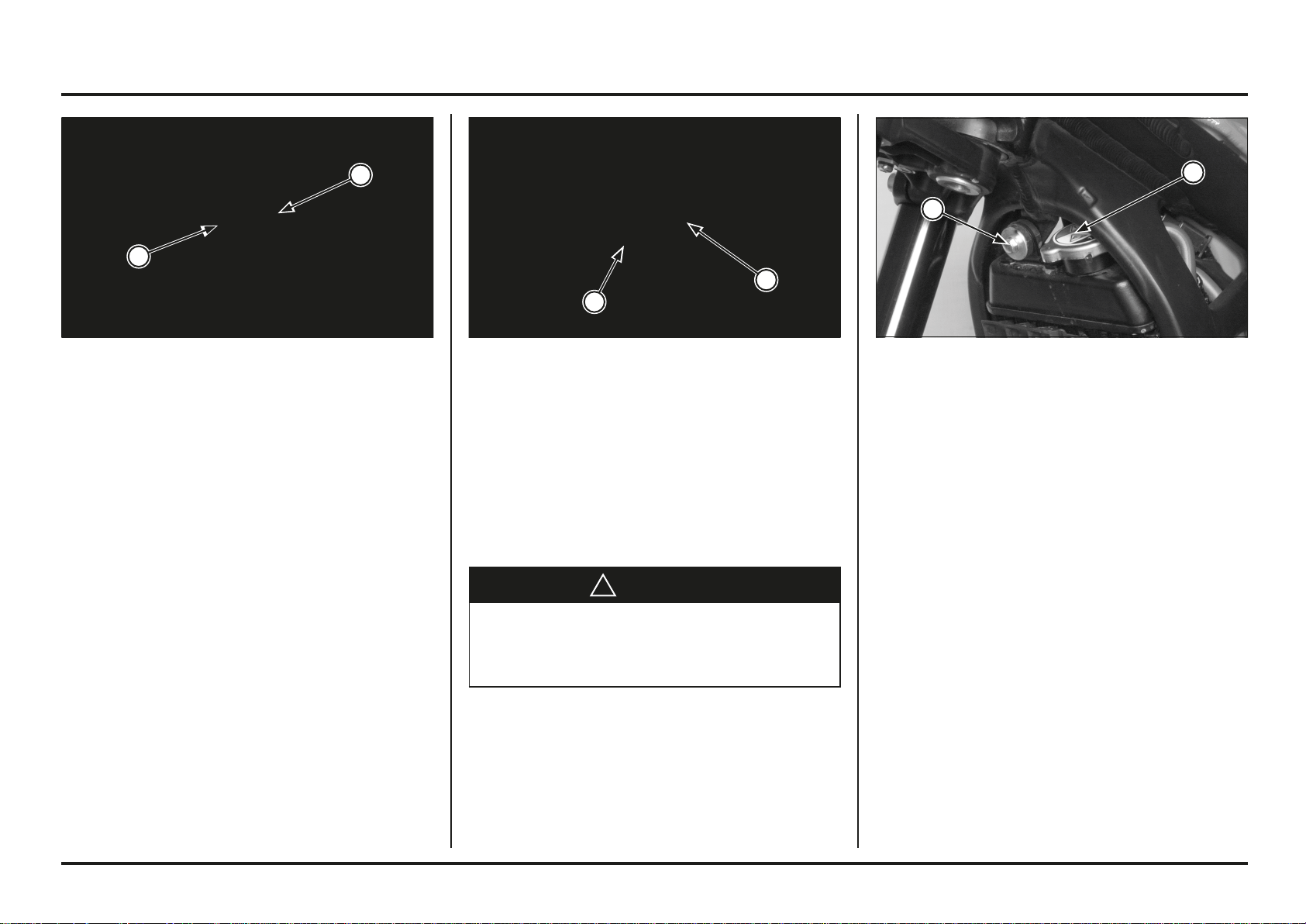
Service and maintenance
3-9
3-9
2.Remove the radiator upper mounting bolt and move
the radiator forward, then remove the radiator cap and
drain the coolant.
3. Install the new sealing washer, drain bolt and tighten it
to the specified torque.
Torque: 9.8 N•m (1.0 kgf•m, 7 lbf•ft)
(1) BOLT
(2) RADIATOR CAP
6. Check the water pump inspection hole bottom of the
water pump for leakage. Make sure the hole remains
open.
If water leaks through the check hole, the water seal
is damaged. If oil leaks through the check hole, the oil
seal is damaged.
Replace the water seal or the oil seal (page 4-15).
Coolant Replacement
!
WARNING
Removing the radiator cap while the engine is hot will
allow the coolant to spray out, seriously scalding you.
Always let the engine and radiator cool down before
removing the radiator cap.
1. Remove the coolant drain bolt and sealing washer.
(1) INSPECTION HOLE
(2) COOLANT DRAIN BOLT/SEALING WASHER
Coolant
Cooling System Inspection
1. Check the cooling system for leaks.
2. Check water hoses for cracks, deterioration, and clamp
bands for looseness.
3. Check the radiator mount for looseness.
4. Make sure the overflow hose is connected and not
clogged.
5. Check radiator fins for obstructions or damage.
(1) OVERFLOW HOSE
(2) RADIATOR
2
1
2
1
1
2
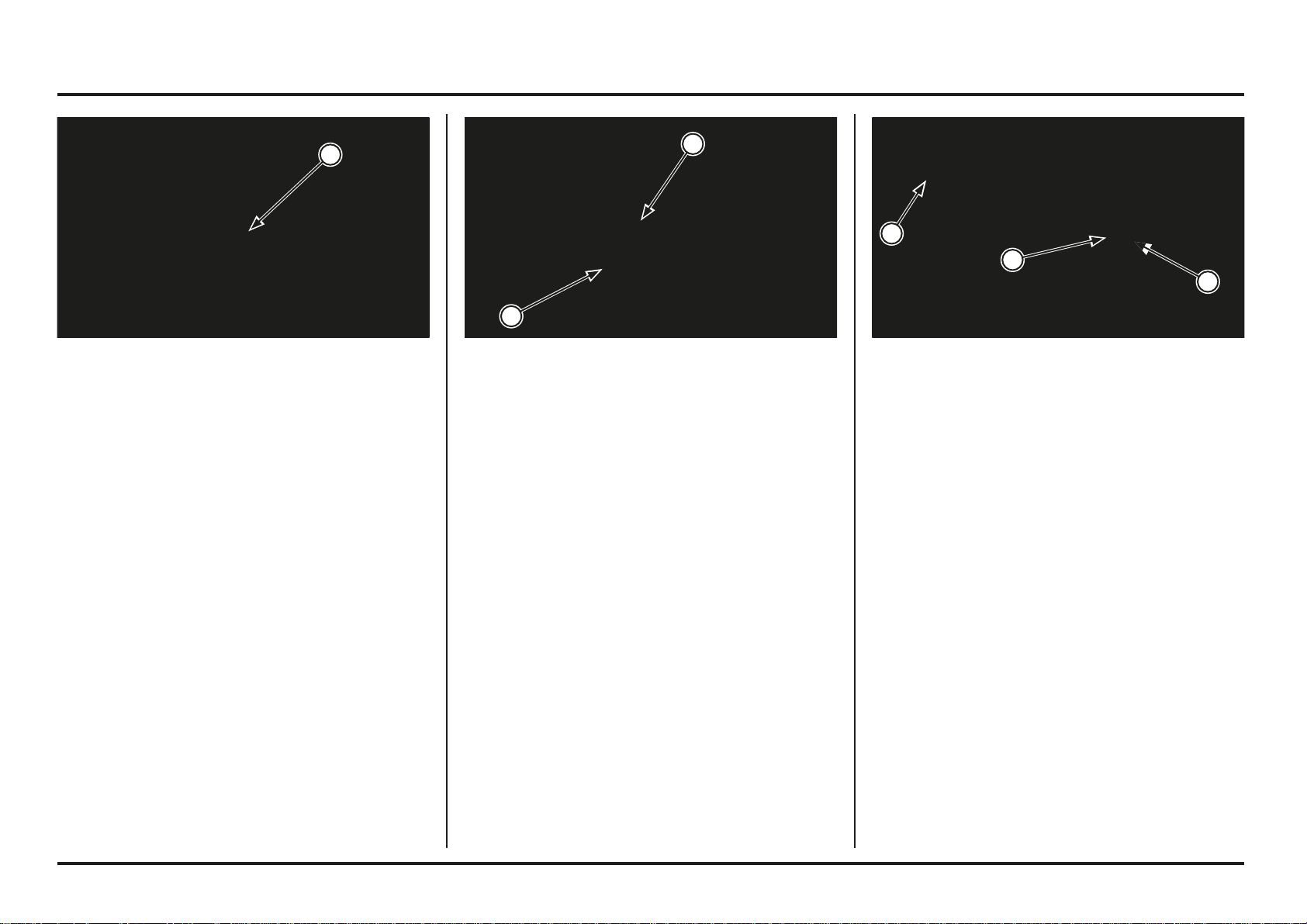
Service and maintenance
3-10
3-10
Exhaust Pipe And Muffler
Inspection
Check the muffler for clogging.
Check for loose or missing bolts and nuts.
Check the exhaust pipe and muffler for cracks or
deformation.
Check the exhaust pipe gasket.
Check the muffler gasket.
Loss of power will result if the exhaust pipe is broken.
(1) EXHAUST PIPE
(2) MUFFLER
(3) LAMBDA-SONDE (2ED)
Clutch System
System Inspection
1. Operate the clutch lever and check that no air has en-
tered in the system. If the clutch is not disengaged
properly, or the lever feels soft or spongy, bleed the air
from the system.
2. Remove the reservoir cover and diaphragm, check the
clutch fluid level. If the level is low, inspect the clutch
hose and fittings for damage, deterioration, cracks or
sign of leakage. Tighten any loose fittings. Replace
hose and fittings as require.
(1) CLUTCH FLUID RESERVOIR
(2) LOWER LEVEL LINE
4. Fill the radiator with coolant up to the filler neck.
5. Squeeze the radiator hoses alternately. If the coolant
level drops, fill the coolant again.
6. Fill the radiator with coolant up to the filler neck.
7. After this first filling, start the engine, check the coo-
lant level (page 1-3).
(1) FILLER NECK
2
1
3
1
2
1
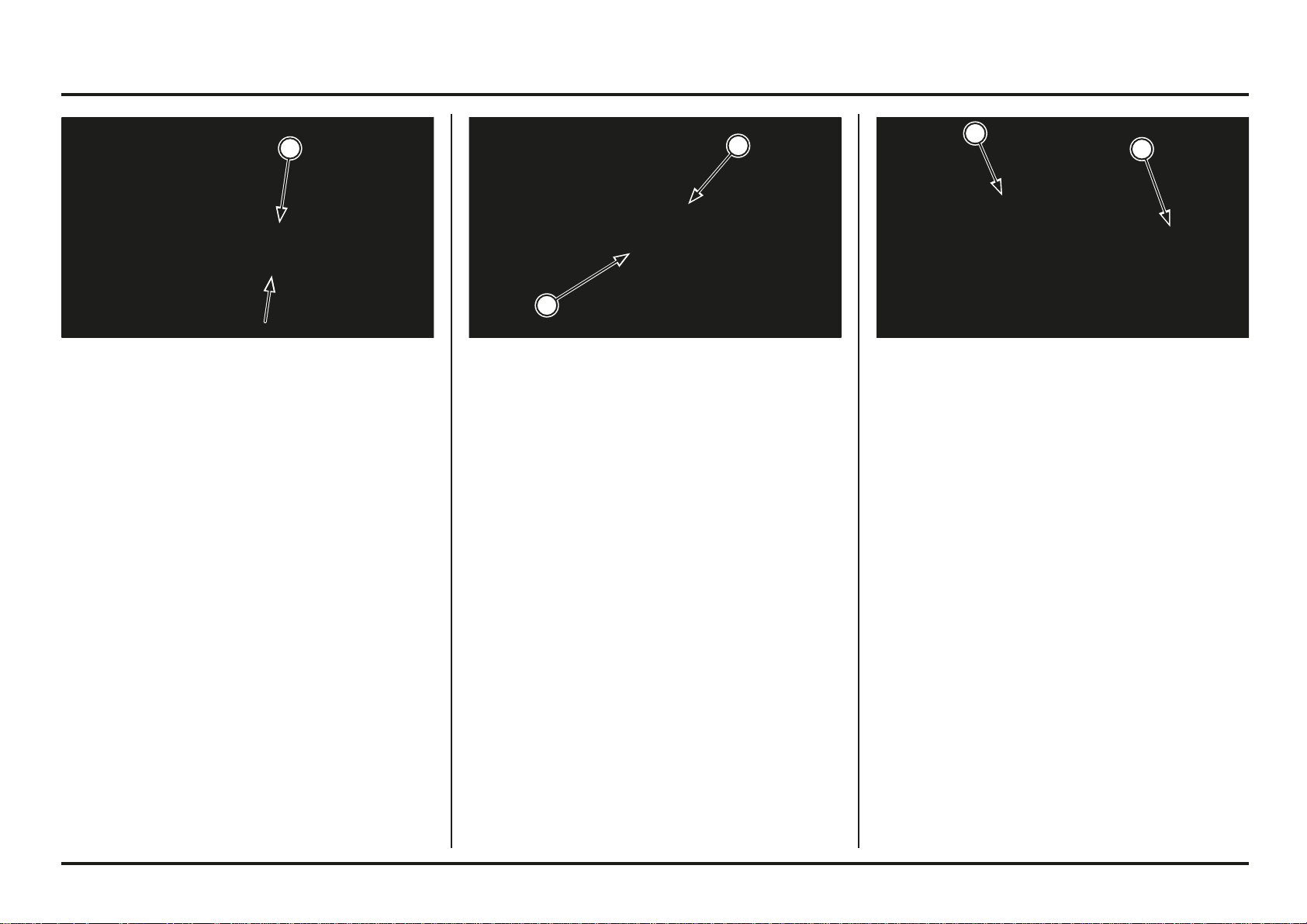
Service and maintenance
3-11
3-11
Drive Chain Slider
Inspection/Replacement
Check the drive chain slider for wear or damage.
If the wear is 2.0 mm (0.08 in) or more, replace the slider.
Check the drive chain tensioner slider for wear or damage.
If the wear is 2.0 mm (0.08 in) or more, replace the slider.
The drive chain slider and tensioner screws must be
retightened after break-in.
(1) DRIVE CHAIN SLIDER
(2) DRIVE CHAIN TENSIONER SLIDER
Drive Chain Slack Adjustment
Loosen the rear axle nut just enough to move the rear
wheel in fore-act direction.
Turn the adjuster equally on both sides until the correct
drive chain tension is obtained.
Turn the adjuster counterclockwise will decrease slack
and turning it clockwise will increase slack.
Adjust the chain with the chain adjusters so that it is
parallel with the center line of the frame.
Check that the stopper is between the teeth of the
adjuster.
Recheck the drive chain slack and free wheel rotation.
After adjustment, tighten the axle nut to the specified
torque.
Torque: 69 N•m (7.0 kgf•m, 51 lbf•ft)
Lubricate the drive chain.
Hook the drive chain tensioner spring.
(1) AXLE NUT
(2) ADJUSTER
Drive Chain
Drive Chain Slack Inspection
During the break-in period, drive chain slack should be
checked and adjusted often. Also check the drive chain
slack after the drive chain replacement.
Regular cleaning, lubrication, and proper adjustment will
help to extend the service life of the drive chain.
Shift the transmission into neutral, turn the engine off and
support the motorcycle on its side stand.
Unhook the drive chain tensioner spring to remove any
load on the chain.
Measure chain slack at the lower section midway between
the sprockets.
Drive chain slack: 25 – 35 mm (1.0 – 1.4 in)
Rotate the wheel and chain slack in several sections.
If slack in one section increases beyond the standard
measurement, this indicates the chain has stretched and
needs to be replaced.
Take care to prevent catching your fingers between the
chain and sprocket.
(1) DRIVE CHAIN SLACK
2
1
2
1
1
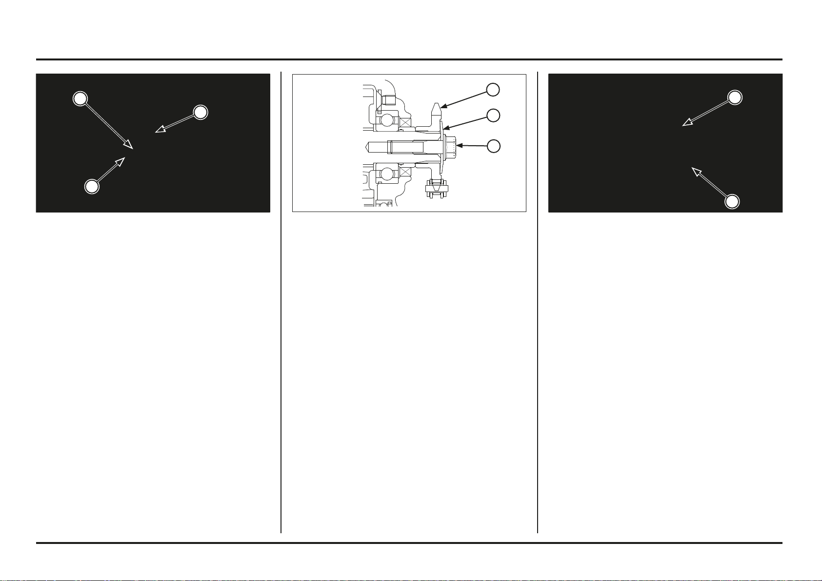
Service and maintenance
3-12
3-12
Driven Sprocket Replacement
Remove the rear wheel (page 5-15).
Remove the bolts/nuts, washers and driven sprocket.
Installation is in the reverse order of removal.
Hold the bolts and tighten the nuts to the specified torque.
Torque:
30 - 35 N•m (3.0 - 3.5 kgf•m, 22.1 - 25.8 lbf•ft)
Adjust the drive chain slack (page 3-11).
(1) BOLTS/NUT
(2) DRIVEN SPROCKET
Install the drive sprocket onto the countershaft as shown.
Install the spring washer and bolt, then tighten the bolt to
the specified torque.
Torque: 31 N•m (3.2 kgf•m, 23 lbf•ft)
Put the transmission in neutral.
(1) DRIVE SPROCKET
(2) SPRING WASHER
(3) BOLT
Drive/Driven Sprockets
Drive Sprocket Replacement
Remove the drive sprocket cover.
Loosen the drive chain fully.
Insert 1st gear
Remove the screw drive pinion and spring washer.
(1) BOLT
(2) SPRING WASHER
(3) DRIVE SPROCKET
2
1
3
2
1
3
2
1
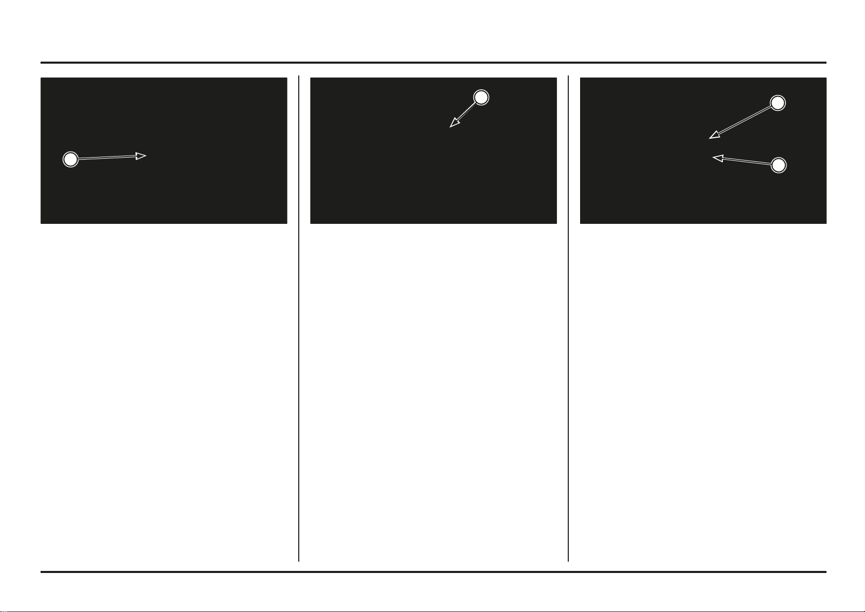
Service and maintenance
3-13
3-13
Rear Master Cylinder
Always inspect the brake fluid level.
Remove the master cylinder reservoir cover, set plate and
diaphragm.
If the fluid level is lower than the “MIN” level, check for
brake pad wear.
Replace the brake pad if necessary.
Refer to page 5-24 for brake pad replacement.
Also check the brake system for leaks.
Replace the brake fluid every 6 months.
Replace the brake hose every year.
Do not service the brake system in high humidity.
Brake fluid: DOT 4 only
(1) COVER
(2) “MIN” LEVEL
Check that the brake hose do not bind or kink in all
steering position, and is not pulled when the suspension
is extended.
Replace the brake fluid every 6 months.
Replace the brake hose every year.
Do not service the brake system in high humidity.
Brake fluid: DOT 4 only
(1) BRAKE HOSE
Brake Fluid
Front Brake Master Cylinder
Always inspect the brake fluid level.
Remove the screws, master cylinder cover and diaphragm.
If the fluid level is lower than the “MIN” line, check for
the brake pad wear.
Replace the brake pad if necessary.
Refer to page 5-24 for brake pad replacement.
Also check the brake system for leaks.
(1) “MIN” LEVEL
2
1
1
1
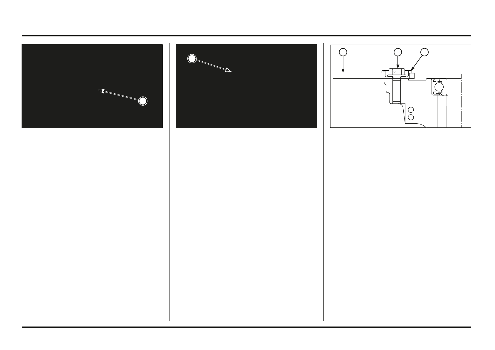
Service and maintenance
3-14
3-14
The front brake is floating type disc.
Replace the disc and disc bolts if the play in the rotating
direction exceeds 2.0 mm (0.08 in), as measured at its
periphery. The standard play is from 0.3 – 1.0 mm (0.01
– 0.04 in).
Apply a locking agent to the threads of the brake disc
bolts before installation.
Torque:
Front: 18 - 20 N•m (1.8 - 2 kgf•m, 13-15 lbf•ft)
Rear: 16 - 18 N•m (1.6 - 1.8 kgf•m, 11-13 lbf•ft)
On the front brake, replace the collar with new ones if the
disc starts to wobble right and left.
(1) BRAKE DISC
(2) DISC BOLT
(3) COLLAR
Brake System
Refer to page 1-11 for Brake Lever Adjustment.
Refer to page 1-12 for Brake Pedal Height Adjustment.
Brake Discs
Measure the rear brake disc runout with a dial gauge.
Service limit: 0.15 mm (0.006 in)
Replace the brake disc if the runout exceeds the service
limit.
Measure the brake disc thickness.
Service limit: Front: 2.5 mm (0.08 in)
Rear: 2.5 mm (0.08 in)
Replace the brake disc if necessary.
Refer to pages 5-1 and 5-15 for removal.
(1) BRAKE DISC
Brake Pad Wear
Measure the brake pad thickness.
Minimum thickness (subtracting the metal support):
1.0 mm (0.04 in)
If either pad is wear, both pads must be replaced.
(1) BRAKE PAD
1
1
321
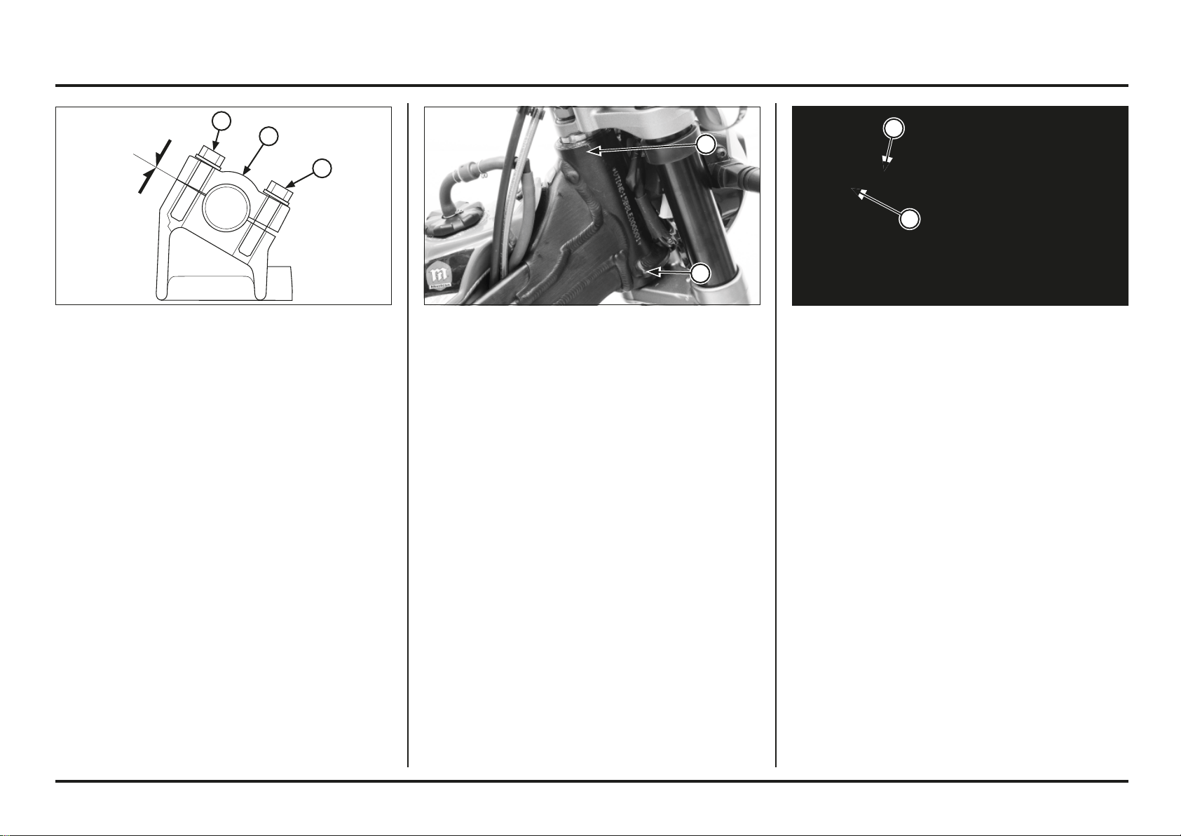
Service and maintenance
3-15
3-15
Wheels And Tires
Proper air pressure will provided maximum stability and
tire life.
Check tire pressure frequently and adjust if necessary.
Tire air pressure should be checked when the tires are
COLD.
Standard tyre air pressure FOR COMPETITION ONLY:
Front: 39 – 44 kPa (0.40 – 0.45 kgf/cm
2
, 5.6 – 6.4 psi)
Rear: 29 – 34 kPa (0.30 – 0.35 kgf/cm
2
, 4.3 – 5.0 psi)
Inspect the wheel for damage.
Check the wheel runout. If runout is noticeable, check
the spokes are tight, or replace the wheel.
Check the axle for runout.
Check the condition of the front and rear wheel bearings.
Check the trueness of the wheel, spoke tension and the
tightness of the rim lock nut.
Tool:
Spoke nipple wrench (front) 07701–0020300
Torque:
Spoke nipple:
Front: 2.45 - 4.9 N•m (0.24 - 0.49 kgf•m, 1.8-3.6 lbf•ft)
Rear: 2 - 3 N•m (0.2 - 0.3 kgf•m, 1.5-2.2 lbf•ft)
Rim lock nut: 13 N•m (1.3 kgf•m, 9 lbf•ft)
(1) SPOKE NIPPLE
(2) RIM LOCK
Steering Head Bearings
Support the motorcycle using the maintenance stand with
its front wheel off the ground.
Turn the handlebar to the right and left to check for
roughness in the steering head bearings. Stand in front of
the motorcycle and grab the fork (at the axle), then push
the fork in and out (toward the engine) to check for play
in the steering head bearings. If any roughness or play is
felt, adjust or replace the steering head bearings.
(1) STEERING HEAD BEARINGS
Handlebar And Steering Head Bearings
Handlebar
Check the handlebar for bends or cracks.
Check that the handlebar has not moved from its proper
position.
Check that the handlebar holder bolts are tight.
If necessary, tighten the holder bolts.
First tighten the forward bolts, then tighten the rear bolts
to the specified torque.
Torque: 22 N•m (2.2 kgf•m, 16 lbf•ft)
(1) HOLDER BOLTS
(2) UPPER HOLDER
1
2
1
1
1
1
2
Service and maintenance
3-16
3-16
Use specified fork fluid which additives to assure
maximum performance of your Cota’s front suspension.
Specified fork fluid:
OJ Racing Special Fork Oil Type 01 (SAE 5W) or
equivalent
Periodically check and clean all front suspension parts
to assure top performance. Check the dust seals for
dust, dirt and foreign materials. Check the fluid for any
contamination.
Make rebound damping adjustments in one-click
increments. Adjusting two or more clicks at a time
may cause you to pass over the best adjustment. Test
ride after each adjustment.
If you become confused about adjustment settings,
return to the standard position and start over.
Standard position:
16 ± 2 clicks from full hard
Fork
The motorcycle is shipped with a light coating of grease
on the forks. This is not an indication of a leak.
The fork should always be adjusted for the rider’s weight
and track conditions by using one or more of the following
methods.
Basically, there are two adjustments you can make to the
front suspension:
Rebound damping (right fork)
Turning the rebound damping adjuster adjusts how
quickly the fork extends.
Spring pre-load (left fork)
Turning the spring pre-load adjuster adjusts the spring
initial pre-load length.
Standard position:
5 ± 0.5 turns out from full soft
Replace the fork fluid every 6 months. See page 5-8,
5-10 for oil level adjustment after changing the fork fluid.
Front Suspension
Inspection
1. Make sure that the fork surfaces and dust seals are
clean.
2. Check for signs of oil leakage. Damaged or leaking
fork seals should be replaced before you ride the mo-
torcycle.
3. Make a quick check of fork operation by locking the
front brake and pushing down on the handlebar several
times.
When your Cota is new, break in your Cota to ensure
that the suspension has worked in.
After break-in, test ride your Cota with the front
suspension at the standard setting before attempting
any adjustments.
(1) PRE-LOAD ADJUSTER (1) REBOUND ADJUSTER
1
1

Service and maintenance
3-17
3-17
Inspection
1. Check for a broken or collapsed spring.
2. Bounce the rear of the machine up and down and check
for smooth suspension action.
3. Check the rear shock absorber for a bent shaft or oil
leaks.
4. Push the rear wheel sideways to check for worn or
loose swingarm bearings. There should be no move-
ment. If movement is felt, replace the pivot bearings
(page 5-17).
When your Cota is new, your suspension will break-in
as you ride.
After break-in is completed, test ride your Cota with
the rear suspension at the standard setting before
attempting any adjustments.
Make all rebound damping adjustment in one-click
increments. Adjusting two or more clicks at a time
may cause you to pass over the best adjustment. Test
ride after each adjustment.
If you become confused about adjustment settings,
return to the standard position and start over.
Standard position:
10 ± 2 clicks from full hard
(1) REBOUND ADJUSTER
Rear Suspension
The swingarm is controlled by a shock absorber. The The
rear shock absorber should always be adjusted for the
rider’s weight and track conditions by using one or more
of the following methods.
Spring pre-load
Turning the spring pre-load adjuster adjusts the spring
initial pre-load length.
Rebound damping
Turning the rebound damping screw adjusts how
quickly the shock absorber extends.
(1) PRE-LOAD ADJUSTER
1
1
Service and maintenance
3-18
3-18
(1) SCREWS
(2) THE HOUSING FOR THE UPPER HEADLIGHT
Front headlight and front and rear position
light.
Replacing the bulbs
Bear in mind the following when replacing the front
headlight bulb.
– Use clean gloves when replacing the bulb. Do not
touch the front headlight bulb with your fingertips,
since this could produce hot spots on the bulb and
cause it to break.
– If you touch the bulb with your bare hands, clean it
with a cloth moistened with alcohol to prevent its
early failure.
Ensure that you replace the dust cover after changing
the front headlight bulb.
The bulb for the front headlight gets very hot when it is
on and remains hot for a while after the front headlight
has been turned off. Ensure that you leave it to cool
before carrying out any maintenance work.
(1) DUST COVER
(2) BULB PAWL
(3) BULB
(4) CONNECTORS
– Remove the housing for the upper headlight.
– Disconnect the connectors.
– Remove the dust cover.
– Unhook the bulb pawl.
– Remove the front headlight bulb .
AVISO
Do not touch the bulb. Fingerprints may create hot spots
that cause the bulb to break.
Fit the bulb, while aligning its tabs with the slots on the
front headlight unit.
Hook the bulb pawl in the slot of the front headlight unit.
Firmly replace the dust cover on the headlight.
Replace the housing for the upper headlight.
2ED
2ED
3
2
1
4
2ED
2ED
2
1
1
1
Service and maintenance
3-19
3-19
6. Inflate the tires to their recommended pressure.
7. Place your COTA on the maintenance stand or equiva-
lent to raise both tires off the ground.
8. Stuff a rag into the muffler outlet. Then tie a plastic
bag over the end of the muffler to prevent moisture
from entering.
9. Cover your COTA and store in a place which is free of
humidity and dust.
Removal from Storage
1. Uncover and clean your COTA.
Change the engine and transmission oil if more than 4
months have passed since the start of storage.
2. Uncover the end of the muffler and remove the rag
from the muffler outlet.
3. Fill the fuel tank with recommended fuel.
4. Pour the recommended coolant slowly from the radia-
tor filler neck.
Bleed the air in the cooling system and install the radia-
tor cap securely (page 1-3).
Storage
Extended storage, such as for winter, requires that you
take certain steps to reduce the effects of non-use. In
addition, it is useful to do the necessary repairs BEFORE
storing your COTA, as if you don’t you could forget these
repairs when you use it again.
Preparing The Motorcycle For Storage
1. Completely clean all parts of your COTA. Wash with
fresh water and wipe dry.
2. Drain the fuel tank into an approved gasoline container.
!
WARNING
Gasoline is highly flammable and is explosive. You can
be burned or seriously injured when draining or refue-
ling.
• Stop engine and keep heat, sparks, and flame away.
• Drain or refuel only outdoors.
• Wipe up spills immediately.
3. Remove the coolant drain bolt at the water pump cover
to drain coolant. Drain coolant into a proper container.
After the coolant has been completely drained, ensure
that the drain bolt sealing washer is in good condition
and reinstall the drain bolt.
4. Lubricate the drive chain.
5. Remove the spark plug and pour a table spoon (15 –
20 cm
3
) of clean engine oil into the cylinder.
With the spark plug grounded or the Engine Stop
Switch pushed, crank the engine several times to dis-
tribute the oil.
Cleaning
Clean your COTA regularly to protect the surface finishes
and inspect for damage, wear or oil leakages.
When washing your COTA, always use water and a mild
detergent (such as dishwashing liquid) to avoid discolo-
ring the decals.
NOTICE
High pressure water (or air) can damage certain parts of
the motorcycle.
Wheel hubs.
Light and engine stop switch.
Muffler outlet.
Electrical components.
Drive Chain.
Brake and clutch master cylinder.
Rubber components.
Plastic components.
Stickers, decals.
Air duct.
1. After cleaning, rinse your COTA thoroughly with plenty
of clean water. Detergent residue can corrode alloy
parts.
2. Dry your COTA, start the engine, and let it run for se-
veral minutes.
3. Lubricate the drive chain immediately after washing
and drying your COTA.
4. Test the brakes before riding your COTA. Several appli-
cations may be necessary to restore normal braking
performance. Braking performance may be impaired
immediately after washing your COTA.

3-20
3-20
Memo
4-1
4-1
(1) SNAP RING
(2) PRESSURE RELIEF VALVE
(1) RELIEF VALVE
(2) O-RING
(1) DRIVEN GEAR
(2) DRIVE PIN
Oil Pressure Relief Valve
Removal/Inspection
Drain the engine oil.
Remove the left crankcase cover (page 4-49).
Remove the snap ring.
Remove the pressure relief valve from the left crankcase
cover.
(1) PRESSURE RELIEF VALVE
(2) SNAP RING
Check the relief valve operation by pushing the relief
valve piston.
Installation
Apply oil to a new O-ring and install it onto the relief valve
groove.
Install the relief valve into the left crankcase cover.
Install the snap ring into the crankcase cover groove
securely.
Install the left crankcase cover (page 4-51).
Oil Pump
Disassembly
Remove the engine from the frame.
Separate the crankcase halves (page 4-54).
Remove the oil pump driven gear and drive pin.
4. Engine servicing
2
1
2
1
2
1
2 1
Engine servicing
4-2
4-2
(1) ONE-WAY REED VALVE
(2) GASKET
(3) DOWEL PINS
(1) DRIVEN GEAR
(2) OIL PUMP SHAFT
(1) SNAP RING
(2) OIL SEAL
(1) OUTER ROTOR
(2) INNER ROTOR
(3) OIL PUMP SHAFT
Remove the one-way reed valve, gasket and dowel pins.
Remove the oil pump shaft, outer and inner rotors.
(1) ONE-WAY REED VALVE
Inspection
Check the oil pump driven gear for wear or damage.
Check the oil pump shaft for wear or damage.
Check the one-way reed valve for damage, replace if
necessary.
Check the oil pump shaft oil seal in the left crankcase for
damage or deterioration, replace if necessary.
Temporarily install the oil pump shaft, inner and outer oil
pump rotors into the right crankcase.
Measure the oil pump tip clearance.
Service limit: 0.20 mm (0.008 in)
3 3
2
1
3
2
1
1
2
1
21
Engine servicing
4-3
4-3
(1) ONE-WAY REED VALVE
(2) DOWEL PINS
(3) NEW GASKET
Install the drive pin into the oil pump shaft hole.
Install the oil pump driven sprocket aligning its groove
with the drive pin.
Install the one-way reed valve into the right crankcase.
Note the direction of the reed valve.
Install the dowel pins and new gasket.
Assemble the crankcase.
Install the removed parts in the reverse order of removal.
(1) OIL PUMP SHAFT
(2) INNER ROTOR (3) FLAT SURFACES
(4) OUTER ROTOR
Assembly
Apply clean engine oil to the oil pump rotors and shaft.
Install the oil pump shaft into the right crankcase.
Install the inner rotor aligning the flat surface between the
rotor and pump shaft.
Install the outer rotor.
(1) DRIVE PIN
(2) DRIVEN SPROCKET
(1) GASKET
Measure the oil pump body clearance.
Standard: 0.15 – 0.20 mm (0.006 – 0.008 in)
Temporarily install the crankcase gasket.
Measure the side clearance using a straight edge and
feeler gauge.
Standard: 0.05 – 0.12 mm (0.002 – 0.004 in)
2
1
2
3
1
2 2
3
1
4
1
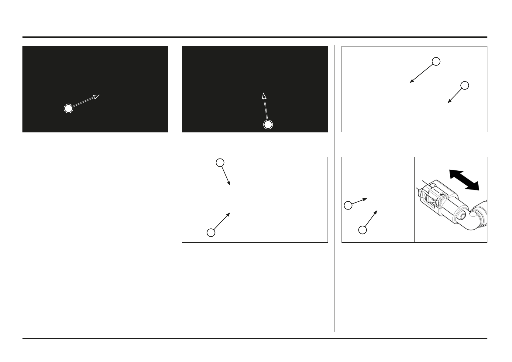
Engine servicing
4-4
4-4
(1) 5P CONNECTOR
Disassembly / Installation of fuel feed hose
The pawl of the fast connector must be changed every
time the fuel feed hose is disconnected.
Disassembly of fuel pump side
Turn off the engine.
Remove the rear fender
Pull up the fuel tank
Disconnect the fuel pump’s 5P connector.
Turn on the engine until it stops.
(1) FAST CONNECTOR PROTECTOR
(1) PAWL
(2) FAST CONNECTOR
1. Remove the protective housing from the fast connec-
tor.
2. Check whether the connector is dirty and clean if ne-
cessary. Cover the fast connector with a cloth.
3. Hold fast connector with one hand and tighten the two
pins of the pawl with the other hand while pulling the
connector backwards. Disconnect the fast connector
and remove the pawl.
(1) PAWL
(2) FAST CONNECTOR
(1) PAWL
(2) FAST CONNECTOR
INSTALLATION OF FUEL PUMP SIDE
1. Insert a new pawl in the fast connector. Insert the fast
connector in the fuel pump feed hose until it clicks. If
this is hard to do, apply a small amount of motor oil to
the fuel pump feed hose.
2. Move the fast connector backwards to check that it
does not come out and is firmly connected.
3. Place the protective housing over the fast connector.
1
1
2
1
2
2
1
1
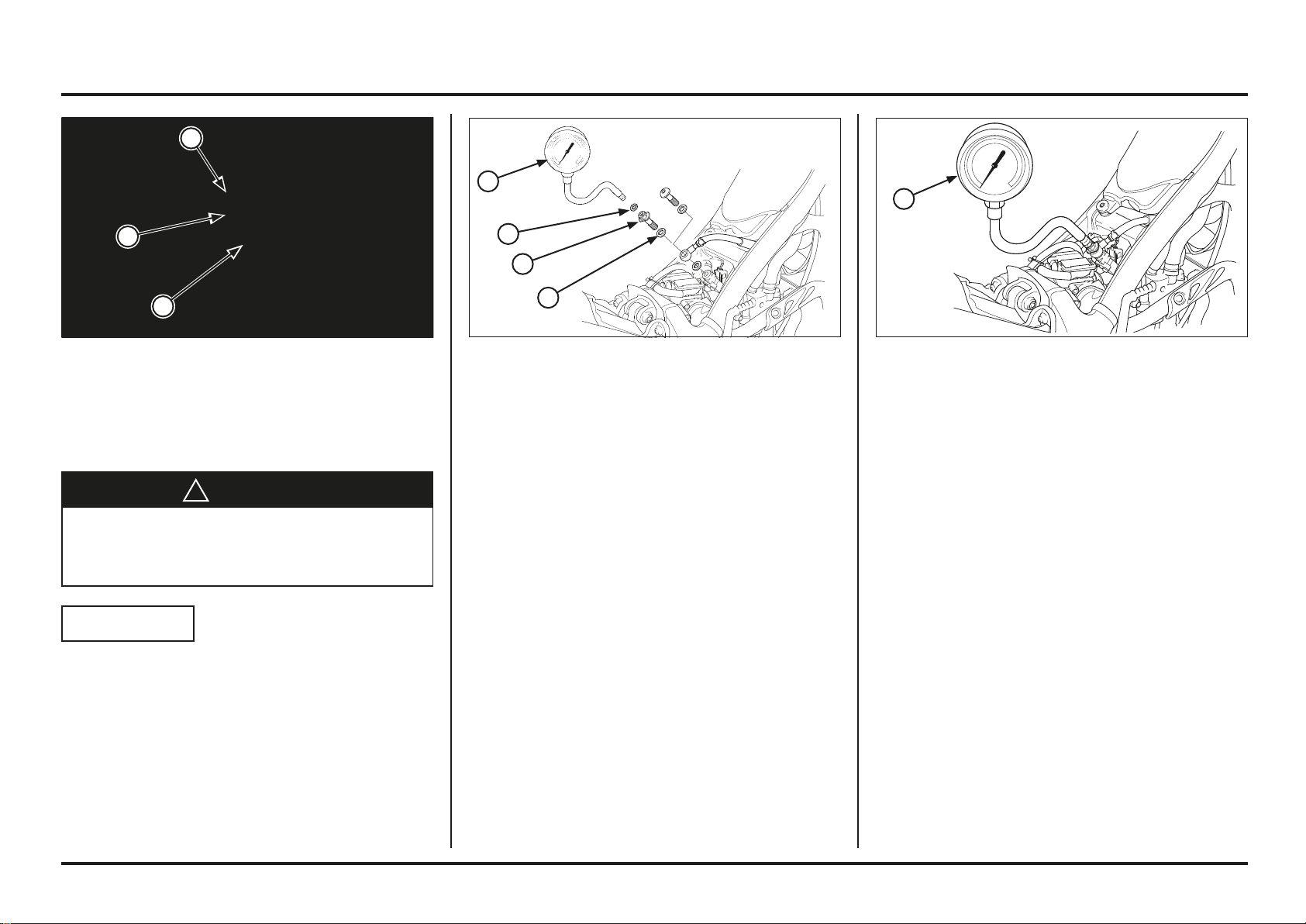
Engine servicing
4-5
4-5
(1) BANJO BOLT
(2) SEALING WASHER
(1) MANOMETER ADAPTER, 12 MM
(2) SEALING WASHER, 12 MM
(3) SEALING WASHER, 6 MM
(4) F. PRESSURE GAUGE
Remove the fuel feed hose banjo bolt and attach the fuel
pressure gauge with the following Montesa Genuine parts.
Manometer adapter, 12 mm
part No. 90008-PP4-E02
Sealing washer, 12 mm
part No. 90428-PD6-003
Sealing washer, 6 mm
part No. 90430-PD6-003
Tool:
Fuel pressure gauge 07406-0040003 or
07406-0040002
(1) FUEL PRESSURE GAUGE
Fuel Line Inspection
Fuel Pressure Inspection
!
WARNING
Gasoline is highly flammable and is explosive.
You can be burned or seriously injured.
Stop engine and keep heat, sparks, and flame away.
Refuel only outdoors.
Wipe up spills immediately.
NOTICE
Before disconnecting the fuel hoses, release the fuel
pressure by loosening the fuel feed hose banjo bolt at
the injector holder.
Always replace the sealing washers when the fuel
hose banjo bolt is removed or loosened.
Remove the rear fender.
Cover the fuel feed hose banjo bolt with a rag or shop
towel.
Slowly loosen the banjo bolt and catch the remaining fuel
using a approved gasoline container.
Start the engine.
Read the fuel pressure at idle speed.
Idle Speed: 1,800 ± 100 min-1 (rpm)
Standard: 230 kPa - 320 kPa
(2,34 kgf/cm
2
- 3,26 kgf/cm
2
)
(33 psi - 46 psi)
If the fuel pressure is higher than specified, inspect the
following:
– Fuel pump (page 4-7)
If the fuel pressure is lower than specified, inspect the
following:
– Fuel line leaking
– Clogged fuel filter
– Fuel pump (page 4-7)
4
3
2
1
1
2
2
1
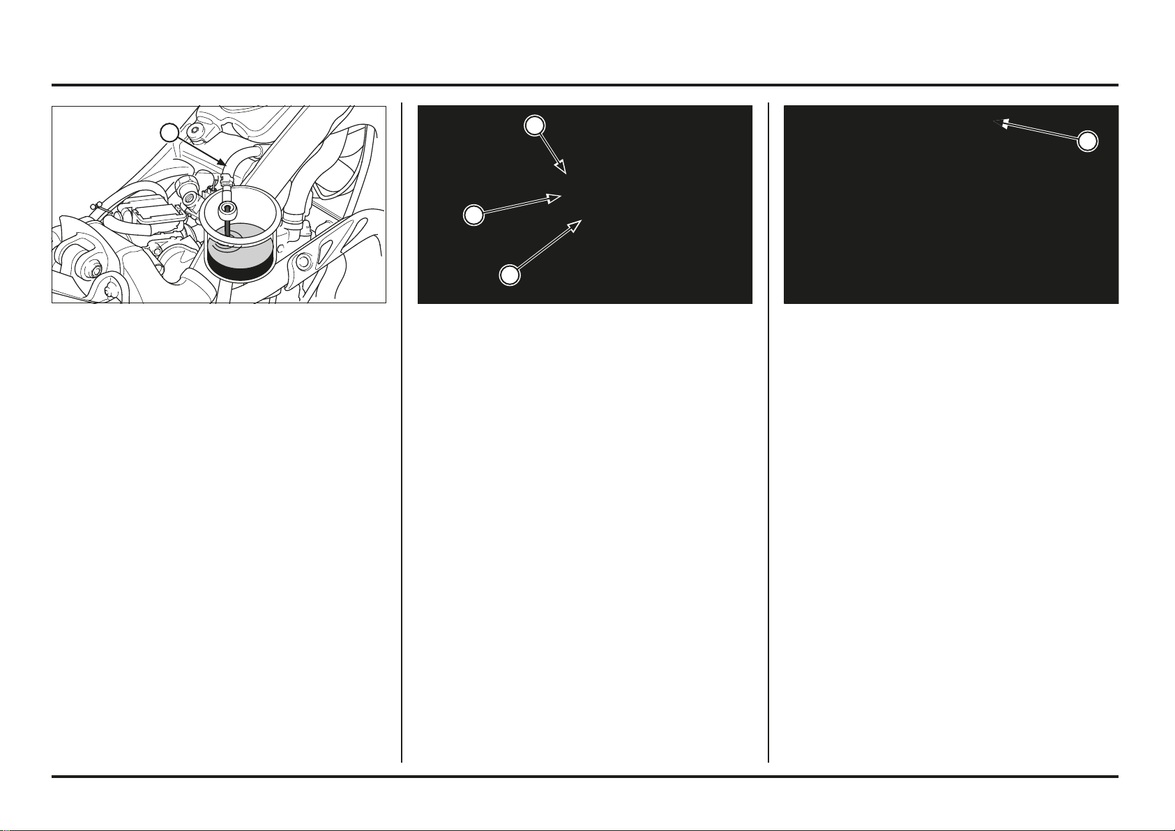
Engine servicing
4-6
4-6
(1) FUEL RETURN HOSE (1) SEALING WASHER
(2) BANJO BOLT
(1) 2P CONNECTOR
Fuel Pump Flow Inspection
Remove the rear fender.
Disconnect el banjo bolt and insert the eyelet of the hose
in a homologated fuel container.
Raise the fuel tank.
Connect the 12 V battery to the fuel pump 2P connector
terminals, check amount of fuel flow for 10 seconds.
Amount of flow:
0.749 l/min (125 cm
3
/ minumun 10 seg)
If the fuel flow is less than specified, inspect the following:
– Pinched or clogged fuel hose
– Clogged fuel filter
– Fuel pump (page 4-7)
After inspection, re-insert the banjo bolt in the fuel feed
hose using a new sealing washer.
Torque: 22 N•m (2,2 kgf•m, 16,2 lbf•ft)
Connect the fuel pump 2P connector.
Start the engine and check for fuel leaks.
1
1
1
1
2
Engine servicing
4-7
4-7
(1) 2P CONNECTOR
(2) SOCKET BOLTS
(1) BREATHER HOSE
(2) BOLT
(3) FUEL TANK
(1) 2P CONNECTOR
Fuel Tank/Fuel Pump
Removal
Remove the rear fender.
Disconnect the injector 2P connector.
Remove the injector holder socket bolts.
Disconnect the fuel tank breather hose.
Remove the fuel tank mounting bolts.
Pull up the fuel tank and disconnect the fuel pump 2P
connector.
Remove the fuel tank and injector as an assembly being
careful not to damage the injector especially tip of the
injector.
After removing the fuel tank/injector assembly, protect tip
of the injector.
Also cover the cylinder head injector hole to prevent dust
and dirt fall into the combustion chamber.
1
2
2
1
3
2
1
Engine servicing
4-8
4-8
(1) QUICK CONNECTOR
(2) FUEL FEED HOSE
(3) 5P CONNECTOR
(1) FUEL PUMP (1) FUEL PUMP
(2) BOLTS
(1) BOLTS
(2) FUEL PUMP
Remove the 5P connector and fuel feed hose.
Remove the fuel pump base mounting bolts.
Remove the fuel pump assembly being careful not to
damage the pump.
Installation
NOTICE
Always replace the packing with a new one when the fuel
pump is removed.
Clean any oil off from the mating surface of the fuel pump
base and fuel tank.
Install a new packing onto the fuel pump base.
Install the fuel pump assembly into the fuel tank (as
pictures shows).
Be careful not to damage the fuel pump wire.
Make sure the packing is seated against the fuel tank.
Also check that the packing is not placed on the fuel tank
boss.
Install the fuel pump mounting bolts.
Tighten the fuel tank mounting bolts in the alphabetical
order shown in the illustration.
Torque: 7 - 9 N•m (0.7 - 0.9 kgf•m, 5.1 - 6.6 lbf•ft)
1
1
2
2
1
2
1
A
C
E
B
G
D
F
3
Engine servicing
4-9
4-9
Install and tighten the injector holder socket bolts to the
specified torque.
Torque: 8 - 12 N•m (0.8 - 1.2 kgf•m, 5.9 - 8.8 lbf•ft)
Connect the fuel injector 2P (Black) connector.
Install the rear fender.
(1) SOCKET BOLTS
(2) 2P (BLACK) CONNECTOR
Install the fuel tank into the frame being careful not to
pinch the throttle cable.
Install and tighten the fuel tank mounting bolts.
Connect the fuel tank breather hose to the hose clip.
(1) FUEL TANK
(2) BOLT
(3) BREATHER HOSE
(1) 2P CONNECTOR
Always replace the injector O-ring with a new one
whenever the injector is removed from the cylinder head.
Install a new O-ring into the injector groove.
Install the fuel feed hose.
Install the fuel tank onto the frame and connect the fuel
pump 2P connector.
(1) O-RING (NEW)
(2) FUEL FEED HOSE
(3) QUICK CONNECTOR
1
2
3
1
2
1
1
1
2
3
4-10
4-10
Engine servicing
(1) CABLE TERMINALS
(2) PUMP ENGINE/FILTER
Cleaning the fuel filter
Press the three pawls between the pump body and the
pump. Remove the body from the pump.
Disconnect the cable terminals (take note initial position).
Disassemble the engine/filter system from the pump body.
(1) PAWL
(2) PUMP BODY
(3) PUMP
(1) FUEL PUMP
Remove the fuel tank.
Remove the bolts from the fuel pump base and remove
the base.
Take the fuel pump out of the fuel tank, taking care not
to damage the pump or electric cables.
(1) BOLTS
(2) FUEL PUMP BASE
(1) FAST CONNECTOR
Disassembly of the fuel filter
Disconnect the 5P connector from the fuel pump.
Disconnect the fuel feed hose (page 4-4).
(1) 5P CONNECTOR
1
1
2
1
1
3
2
1
1
2
1
4-11
4-11
Engine servicing
(1) BEARING
(2) PUMP
Assembly
Insert the body in the pump system.
Make sure that the pawls are tightly closed and that the
two pieces are perfectly positioned.
Insert a new bearing in its housing in the tank as shown.
Insert the pump in the tank, taking special care not to
damage the bearings. Apply a small amount of engine oil
for installation.
Make sure that the bearing is properly positioned and sup-
ported in the fuel tank.
(1) PUMP (3) PAWLS
(2) BODY (4) CONNECTING PIPE
(1) BEARINGS
(2) PUMP
(3) ENGINE CABLES
(4) MOTOR
(5) BODY
Replace the bearings with new ones every time the fuel
pump is disassembled.
Clean the contact surface between the pump and the fuel
tank. Install new bearings. Apply a small amount of engi-
ne oil for installation.
Thread the engine cables through the holes and connect
them to the terminals.
Insert the pump engine in the body.
Be careful not to damage the cables
Clean the surface of the filter.
(1) FILTER SURFACE
5
4
3
2
1
1
1
2
3
3
2
1
4
4-12
4-12
Engine servicing
(1) FUEL PUMP BASE
(2) BOLTS
(1) TANK
(2) CLIP
(3) BREATHER HOSE
(1) PUMP CONNECTOR
Insert the mounting bolts in the pump.
Place the pump base in its position as shown.
Tighten the pump mounting bolts in alphabetical order as
shown in the image.
Torque: 7 - 9 N•m (0.7 - 0.9 kgf•m, 5.1 - 6.6 lbf•ft)
Mount the tank on the chassis.
Connect the breather hose to the tank and secure it with
the clip.
(1) 5P CONNECTOR
Insert the fast connector in the pump (page 4-4).
Connect the fuel pump’s 5P connector.
A
C
E
B
G
D
F
1
1
1
2
2
1
3
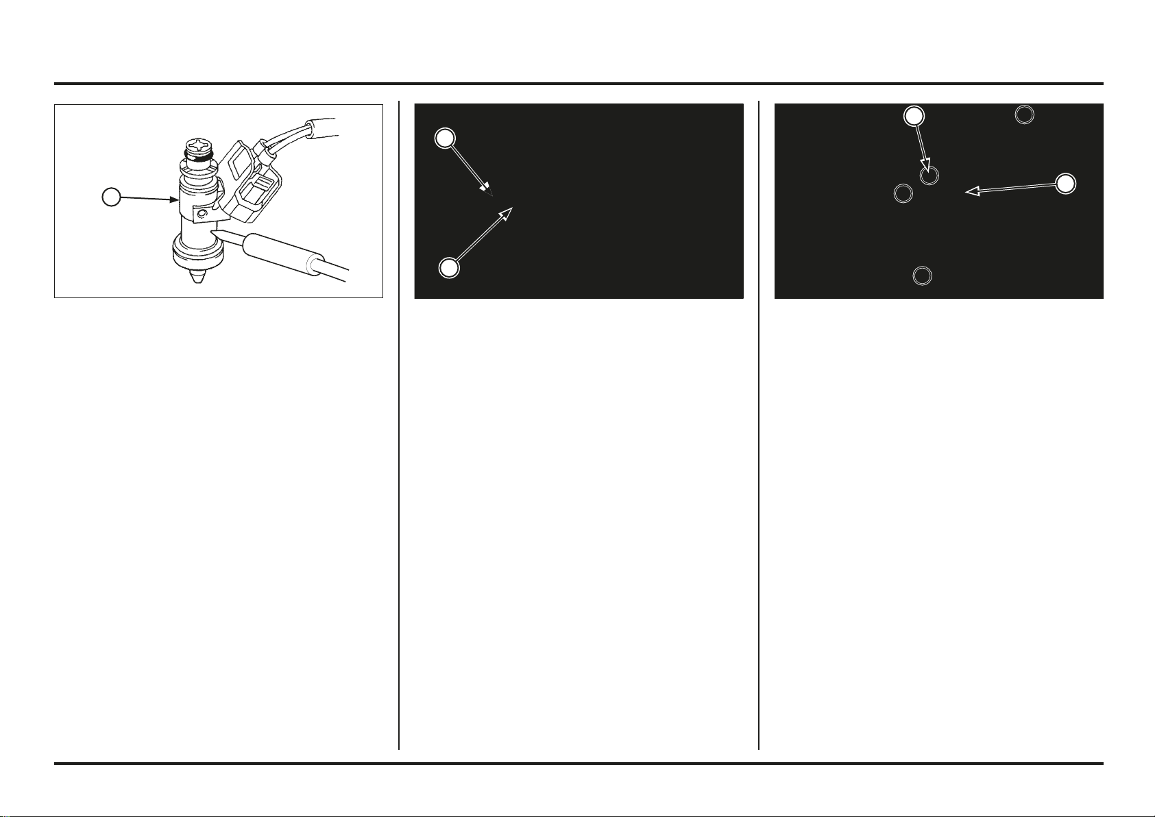
Engine servicing
4-13
4-13
Throttle Body
Removal
Remove the rear fender.
Loosen the connecting tube band screw.
Remove the silencer mounting bolt.
Remove the air cleaner housing mounting nuts and bolt.
Pull the air cleaner housing backward being careful not to
damage the wire harness.
Disconnect the crankcase breather hose from the housing
joint.
(1) BOLTS/NUTS
(2) AIR CLEANER HOUSING
Removal/Installation
Do not remove the injector from the injector holder.
Replace the injector and holder as an assembly.
Always replace the O-ring when the fuel injector assembly
is removed from the cylinder head.
(1) INJECTOR
(2) NEW O-RING
Injector
Inspection
Remove the rear fender.
Start the engine and let it idle.
Confirm the injector operating sounds with a sounding rod
or stethoscope.
If the injector does not operate, replace the injector.
(1) INJECTOR
2
1
1
2
1
Engine servicing
4-14
4-14
(1) THROTTLE DRUM COVER
(2) SCREWS
Connect the throttle cable end to the throttle drum.
Install the throttle cable to the throttle body.
Adjust the throttle grip free play.
Install the throttle drum cover and tighten the screws.
(1) THROTTLE CABLE END (2) THROTTLE DRUM
(3) THROTTLE CABLE (4) LOCK NUT
(1) SCREW
(2) INSULATOR
(3) ALIGN
Loosen the lock nut, then disconnect the throttle cable
from the throttle body.
Then disconnect the cable end from the throttle drum.
Loosen the insulator clamp screw, then remove the
insulator from the throttle body.
Installation
Install the insulator onto the throttle body while aligning
its slit with the lug on the throttle body as shown.
(1) LOCK NUT (2) THROTTLE CABLE
(3) THROTTLE CABLE END (4) THROTTLE DRUM
(1) SCREWS
(2) THROTTLE DRUM COVER
Disconnect the ECM 32P (Black) connector.
Loosen the insulator band screw, then remove the throttle
body.
Be careful to not pull connector from throttle body, pull
up fixation handle.
Remove the screws and throttle drum cover.
(1) 32P (BLACK) CONNECTOR
(2) BAND SCREW
(3) THROTTLE BODY
3
2
1
2
1 1
3 1
4 2
2 3
1 4
3
2
1
1
2 2
Engine servicing
4-15
4-15
Install the throttle body together with insulator at cylinder
head inlet port.
Make sure there are following clearance between the
throttle body:
– Throttle body-to-bank angle sensor: more than 5 mm
– Throttle body-to-silencer: more than 5 mm
Adjust the insulator band angle, tighten the band screw
securely.
Connect the ECM 32P (Black) connector.
(1) THROTTLE BODY
(2) BAND SCREW
(3) 32P (BLACK) CONNECTOR
(1) IMPELLER
(2) COPPER WASHER
(3) WATER PUMP SHAFT
(4) WASHER
Water Seal And Bearing Replacement
Drain the transmission oil (page 3-8).
Remove the following:
– Water pump cover bolt/cover/dowel pins/O-ring
– Right crankcase cover and washer (page 4-40)
Hold the water pump gear teeth using a suitable tool,
then remove the impeller, copper washer and water pump
shaft.
(1) BOLTS
(2) WATER PUMP COVER
Install the air cleaner housing onto the frame and connect
the crankcase breather hose.
Install and tighten the air cleaner housing mounting nuts
and bolt securely.
Install the washer and silencer mounting bolt, then tighten
the bolt securely.
Adjust the angle of the connector tube clamp and tighten
the screw firmly.
Install the rear fender.
(1) AIR CLEANER HOUSING
(2) BOLTS/NUTS
1
2
3
1
2
2
1
4
3
2
1
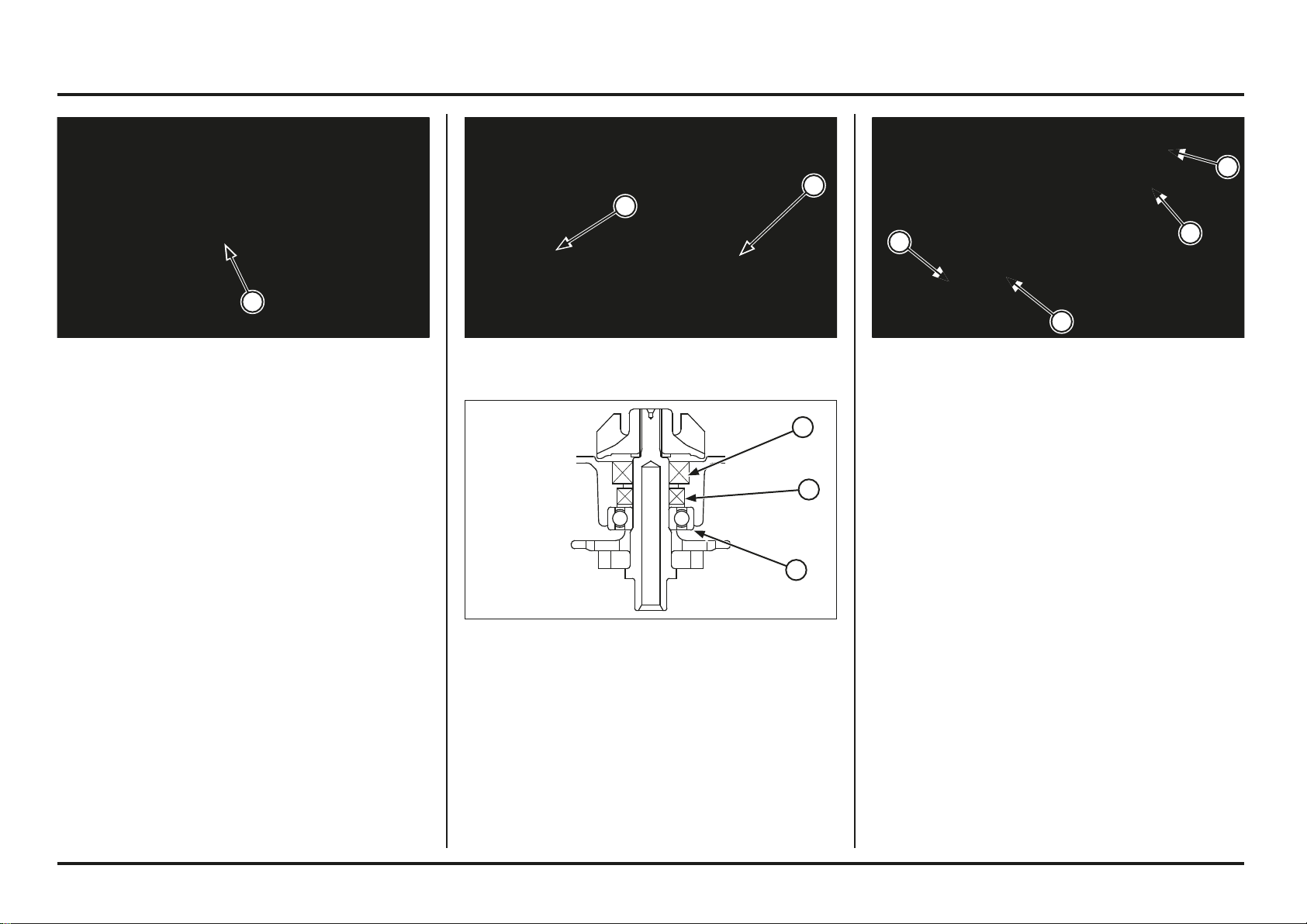
Engine servicing
4-16
4-16
Remove the water pump bearing from the right crankcase
cover using the special tools.
Tools:
Bearing remover, 12 mm Generic tool
– Remover shaft 07936-1660120
– Remover weight 07741-0010201
Remove the oil seal and water seal.
(1) BEARING REMOVER, 12 MM (1) WASHER
(2) WATER PUMP SHAFT
(3) NEW COPPER WASHER
(4) IMPELLER
Install the water pump shaft, new copper washer and
impeller into the right crankcase cover.
Hold the water pump gear using a suitable tool and tighten
the impeller to the specified torque.
Torque: 12 N•m (1.2 kgf•m, 9 lbf•ft)
Install the washer and right crankcase cover (page 4-41).
(1) WATER SEAL
(2) OIL SEAL
(3) BEARING
Install the water seal into the right crankcase cover in the
direction shown in the illustration above.
Tool:
Water seal driver 07945-KA30000
Install a new oil seal in the direction shown in the
illustration above.
Drive the new bearing into the right crankcase cover
(Tools; page 2-8).
(1) WATER SEAL DRIVER
(2) DRIVER/ATTACHMENT
1
2
1
3
2
1
1
2
3
4
Engine servicing
4-17
4-17
(1) WATER PUMP COVER
(2) BOLTS
Install the following:
– Dowel pins, new O-ring
– Water pump cover, bolts
Fill the crankcase with recommended transmission oil
(page 3-8).
Fill the coolant and bleed air (page 1-3).
(1) DOWEL PINS
(2) NEW O-RING
(3) WATER PUMP COVER
(1) 3P (GRAY) CONNECTOR
Remove the ground eyelet bolt.
Remove the ignition coil mounting bolt.
Remove the spark plug wire/wire harness/breather hose
clamp.
Disconnect the ECT sensor 3P (Gray) connector.
(1) GROUND EYELET
(2) BOLTS
(3) IGNITION COIL
(4) WIRE CLAMP
(1) 2P (NATURAL) CONNECTOR
(1) TIE WRAP
Radiator Removal/Installation
Remove the following:
– Exhaust pipe
– Skid plate
– Fuel tank/injector assembly (page 4-7)
Disconnect the radiator 2P (Natural) connector.
Remove the spark plug wire tie-wrap from fan motor
shroud.
3
2
1
1
1
2
1
1
4
3
2
2
1
1
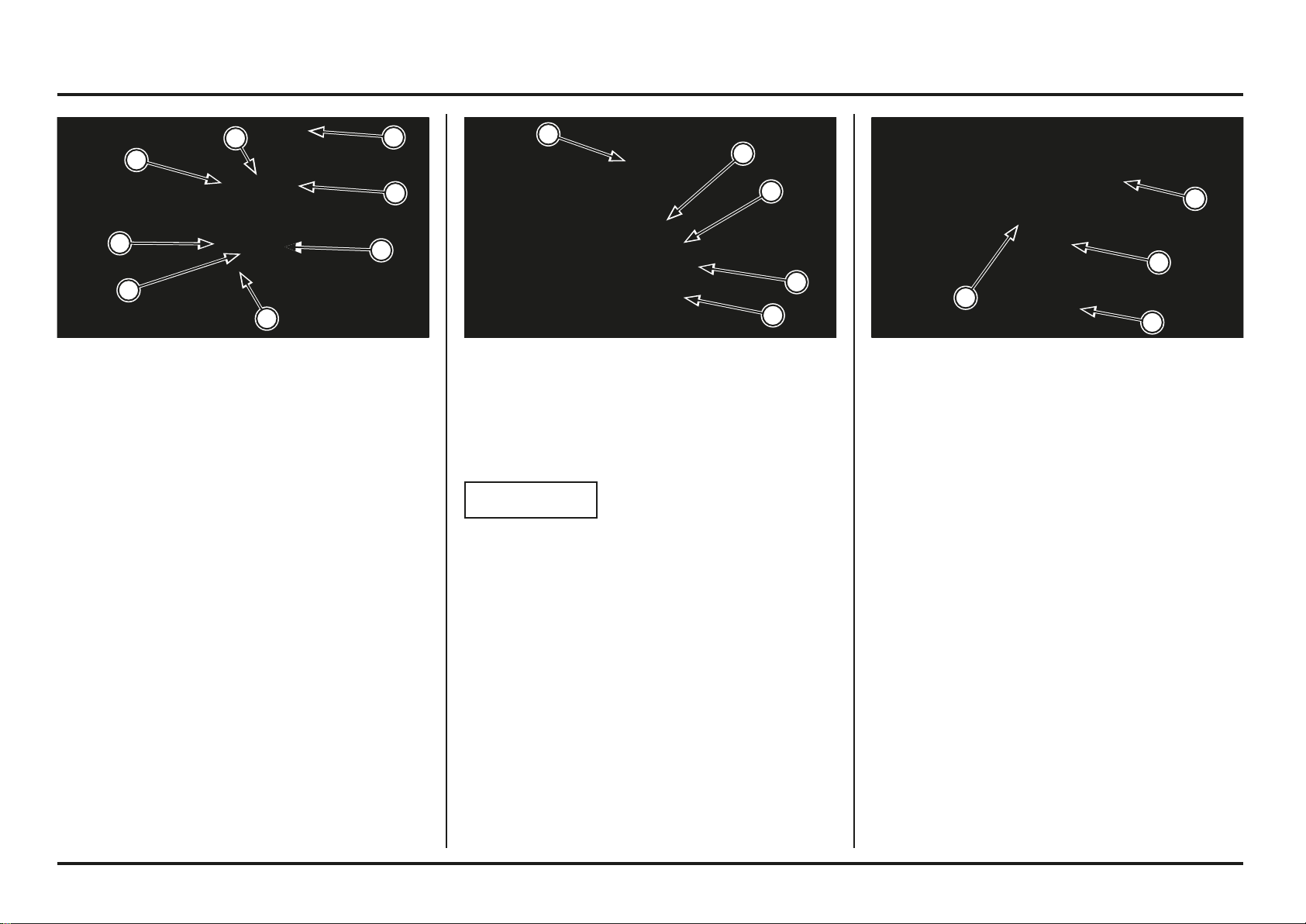
Engine servicing
4-18
4-18
(1) RADIATOR
(2) EXHAUST PIPE
(3) MUFFLER
(4) SKID PLATE
Engine Removal/Installation
Support the motorcycle securely using a hoist or
equivalent.
The following parts must be removed before engine
removal.
– Exhaust pipe, muffler
– Skid plate
– Down tubes, radiator (page 4-17)
– Air cleaner housing (page 4-13)
The following components can be serviced with the
engine in the frame.
– Cylinder head
– Clutch/gearshift linkage
– Flywheel/stator
– Kickstarter/gearshift linkage
The following components require engine removal for
servicing.
– Crankshaft
– Oil pump
– Shift forks and shift drum
– Transmission
– Cylinder/piston
(1) IGNITION COIL
(2) BOLTS
(3) GROUND EYELET
(4) WIRE CLAMP
Installation is in the reverse order of removal.
NOTICE
At ignition coil installation, install the ground eyelet with
the ignition coil lower mounting bracket bolt as shown in
the illustration.
(1) RADIATOR HOSES
(2) HANGER BOLT
(3) DOWN TUBE BOLTS
(4) DOWN TUBES
(5) BOLT
(6) RADIATOR
Disconnect the radiator hoses at the right crankcase cover
and cylinder head.
Remove the front engine hanger bolt and front down tube
mounting bolts, then remove the down tubes.
Remove the radiator mounting bolt, then remove the
radiator assembly.
4
3
2
2
1
6
5
4
2
3
1
1
4
3
2
1
4
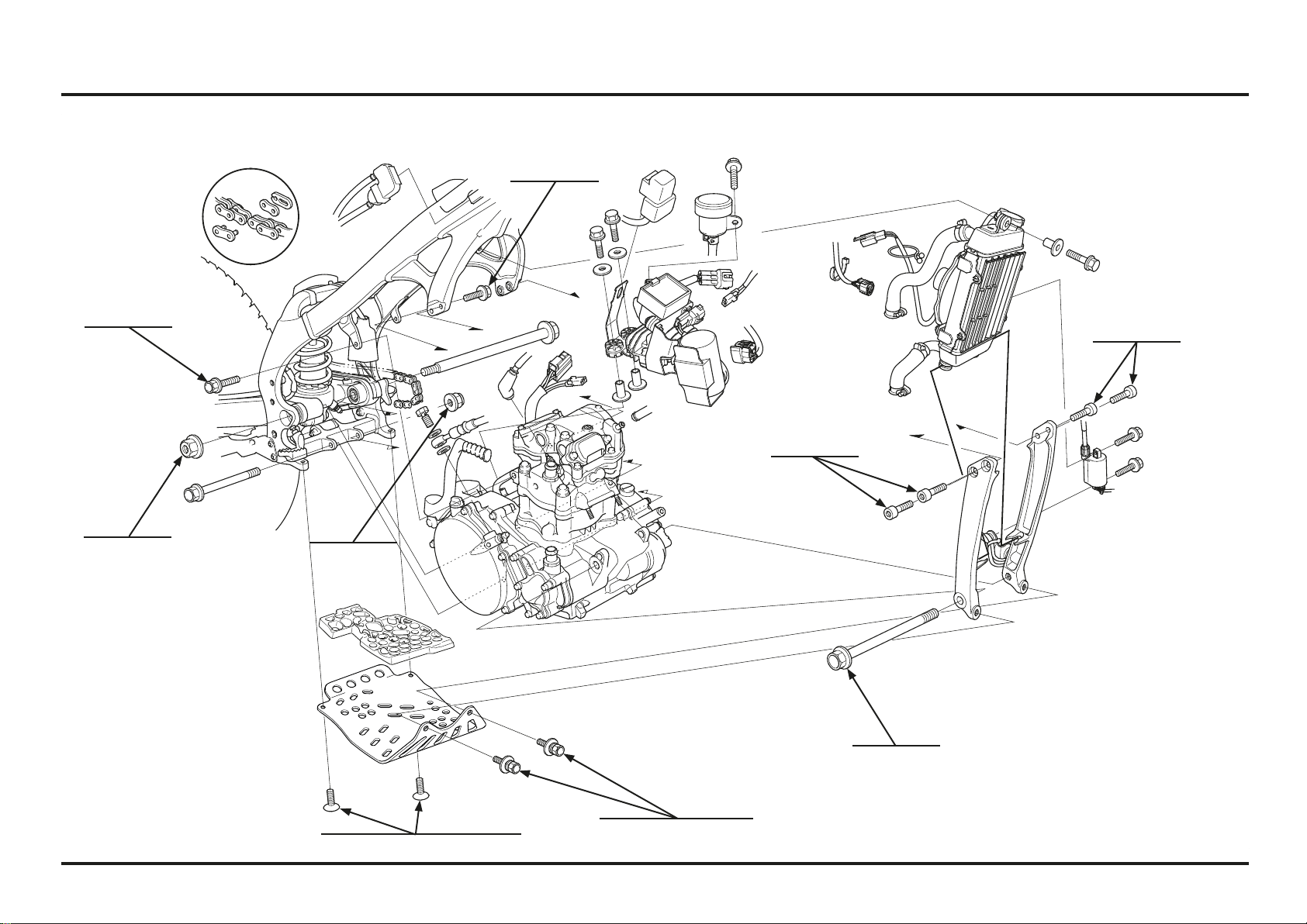
4-19
4-19
Engine servicing
Engine Removal/Installation Illustration
24 N•m
(2.4 kgf•m)
(17.8 lbf•ft)
24 N•m
(2.4 kgf•m)
(17.8 lbf•ft)
26 N•m
(2.6 kgf•m)
(19.2 lbf•ft)
26 N•m
(2.6 kgf•m)
(19.2 lbf•ft)
69 N•m
(6.9 kgf•m)
(50.9 lbf•ft)
39 N•m
(4.0 kgf•m)
(28.7 lbf•ft)
50 N•m
(5.1 kgf•m)
(36.8 lbf•ft)
26 N•m (2.7 kgf•m) (19.1 lbf•ft)
26 N•m
(2.7 kgf•m) (19.1 lbf•ft)

Engine servicing
4-20
4-20
(1) “T” MARK
(2) INDEX MARK
Remove the fuel tank/injector.
Remove the timing hole cap and O-ring from the left
crankcase cover.
Turn the crankshaft by operating the kickstarter and align
the “T” mark on the flywheel with the index mark on the
left crankcase cover.
(1) TIMING HOLE CAP
(1) CAM CHAIN TENSIONER LIFTER
Cylinder Head Cover/Camshaft Removal
Remove the cam chain tensioner lifter sealing bolt and
sealing washer.
Turn the tensioner lifter clockwise fully and secure it with
the stopper tool.
This tool can be easily be made from a thin (1 mm thick)
piece of steel as shown.
(1) SEALING BOLT/WASHER
(2) STOPPER TOOL
(1) CYLINDER COMPRESSION GAUGE
Cylinder Compression
Warm up the engine to normal operating temperature.
Stop the engine and remove the spark plug.
Install a compression gauge.
Shift the transmission into neutral.
Open the throttle all the way and crank the engine with
the kickstarter until the gauge reading stops rising.
Compression pressure:
1,300 kPa (13.3 kgf/cm
2
, 189 psi)
Low compression can be caused by:
– Blown cylinder head gasket
– Improper valve adjustment
– Valve leakage
– Worn piston ring or cylinder
High compression can be caused by:
– Incorrect valves adjustment
1
2
1
2
1
1
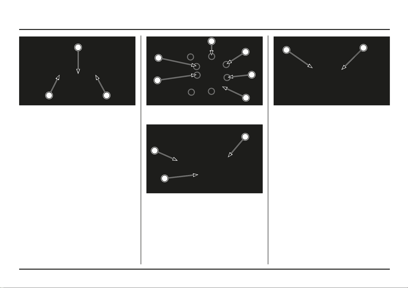
Engine servicing
4-21
4-21
(1) CAM CHAIN
(2) CAMSHAFT
(1) SIDE CAP
(2) DOWEL PINS
Disconnect the crankcase breather hose.
Remove the two 6 mm bolts.
Loosen the eight cylinder head cover SH bolts in crisscross
pattern in 2 or 3 steps.
Remove the bolts and four sealing washers.
Remove the cylinder head cover assembly.
Remove the dowel pins.
Remove the cylinder head side cap.
Remove the camshaft bearing retainer from the cylinder
head cover.
(1) BOLTS/SEALING WASHERS (2) SH BOLTS
(3) SEALING WASHERS (4) CYLINDER HEAD COVER
(1) BOLTS
(2) TAPPET ADJUSTING HOLE COVER
Remove the bolts and tappet adjusting hole covers.
Make sure the piston at TDC (Top Dead Center) on the
compression stroke by moving the rocker arms.
Remove the cam chain from the cam sprocket and
suspend the cam chain with a piece of wire to prevent it
from falling into the crankcase.
Remove the camshaft assembly.
2
1 1
4
3
3
2
1
1
2
1
2
2
1
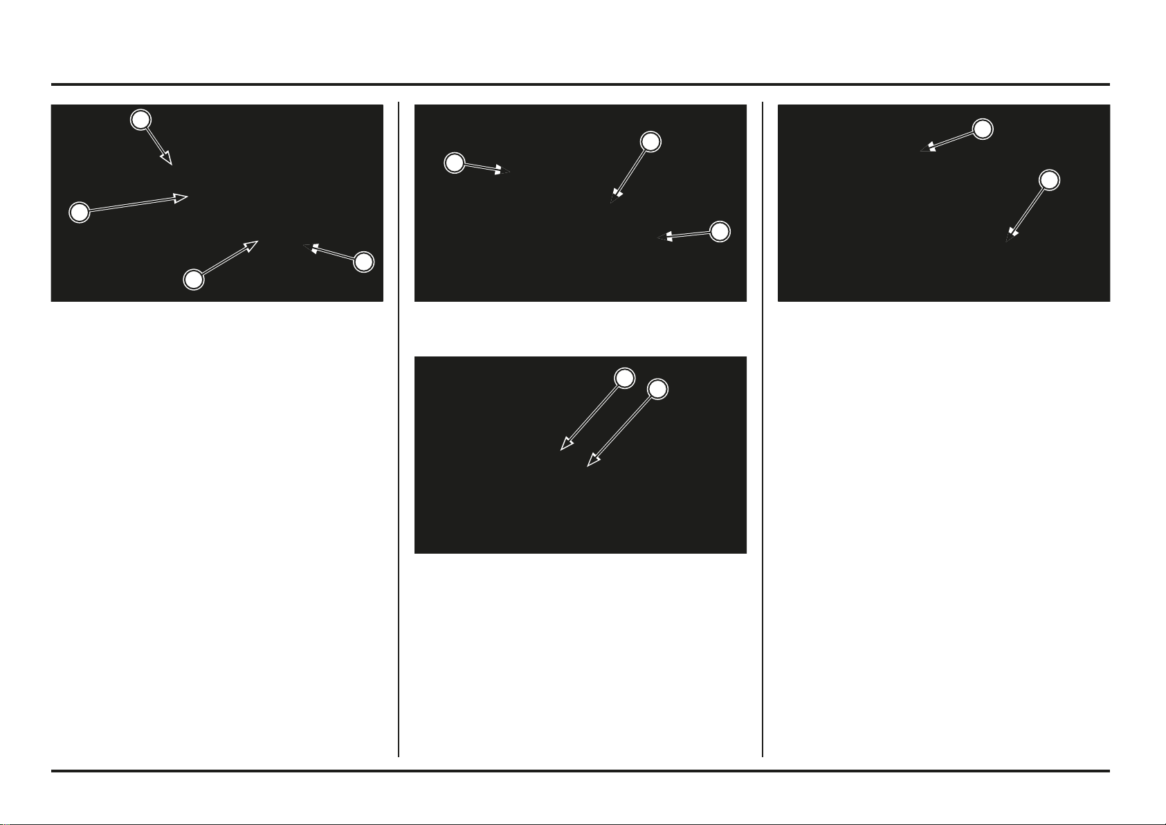
Engine servicing
4-22
4-22
(1) ROCKER ARM
(2) ROCKER ARM SHAFT
(1) DECOMPRESSOR
(2) RETURN SPRING
Inspection
Remove the bearings from the camshaft.
Turn the inner race of each bearing with your finger.
The bearing should turn smoothly and quietly.
Replace the bearing if the bearing do not turn smoothly
and quietly.
Check the decompressor cam for wear or damage.
If any components are faulty, replace the camshaft
assembly.
(1) BEARINGS
(2) CAMSHAFT
(1) INTAKE ROCKER ARM SHAFT
(2) EXHAUST ROCKER ARM SHAFT
(3) INTAKE ROCKER ARM
(4) EXHAUST ROCKER ARM
Disassembly
Pull out the rocker arm shafts using a suitable 6 mm bolt
and remove the intake and exhaust rocker arms.
Check the rocker arms and shafts for wear or damage.
Measure the rocker arm I.D.
Service limit: 10.051 mm (0.3957 in)
Measure the rocker arm shaft O.D. at rocker arm sliding
portion.
Service limit: 9.925 mm (0.3907 in)
4
3
2
1
2
1
1
2
1
2
1
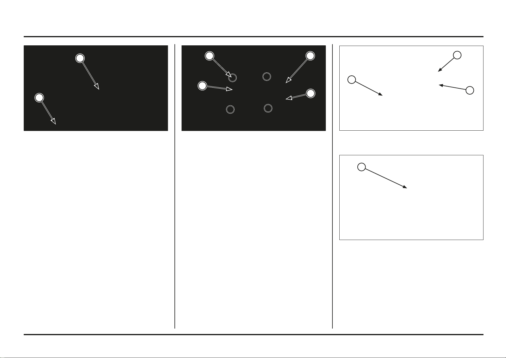
Engine servicing
4-23
4-23
(1) CAM CHAIN GUIDE
Remove the gasket and dowel pins.
Remove the cam chain guide.
(1) GASKET
(2) DOWEL PINS
Remove the cylinder head mounting bolts.
Loosen the cylinder head mounting nuts in a crisscross
pattern in two or three steps.
Remove the nuts, washers and cylinder head.
(1) BOLTS
(2) NUTS/WASHERS
(3) CYLINDER HEAD
Cylinder Head Removal
Remove the following:
– Exhaust pipe
– Throttle body/insulator
– Cylinder head cover/camshaft
– Spark plug
Drain the coolant.
Loosen the hose band screw and disconnect the upper
radiator hose from the cylinder head.
Remove the upper engine hanger bolts.
(1) RADIATOR HOSE
(2) HANGER BOLTS
2
1
3
2
1
1
2
2
1
1
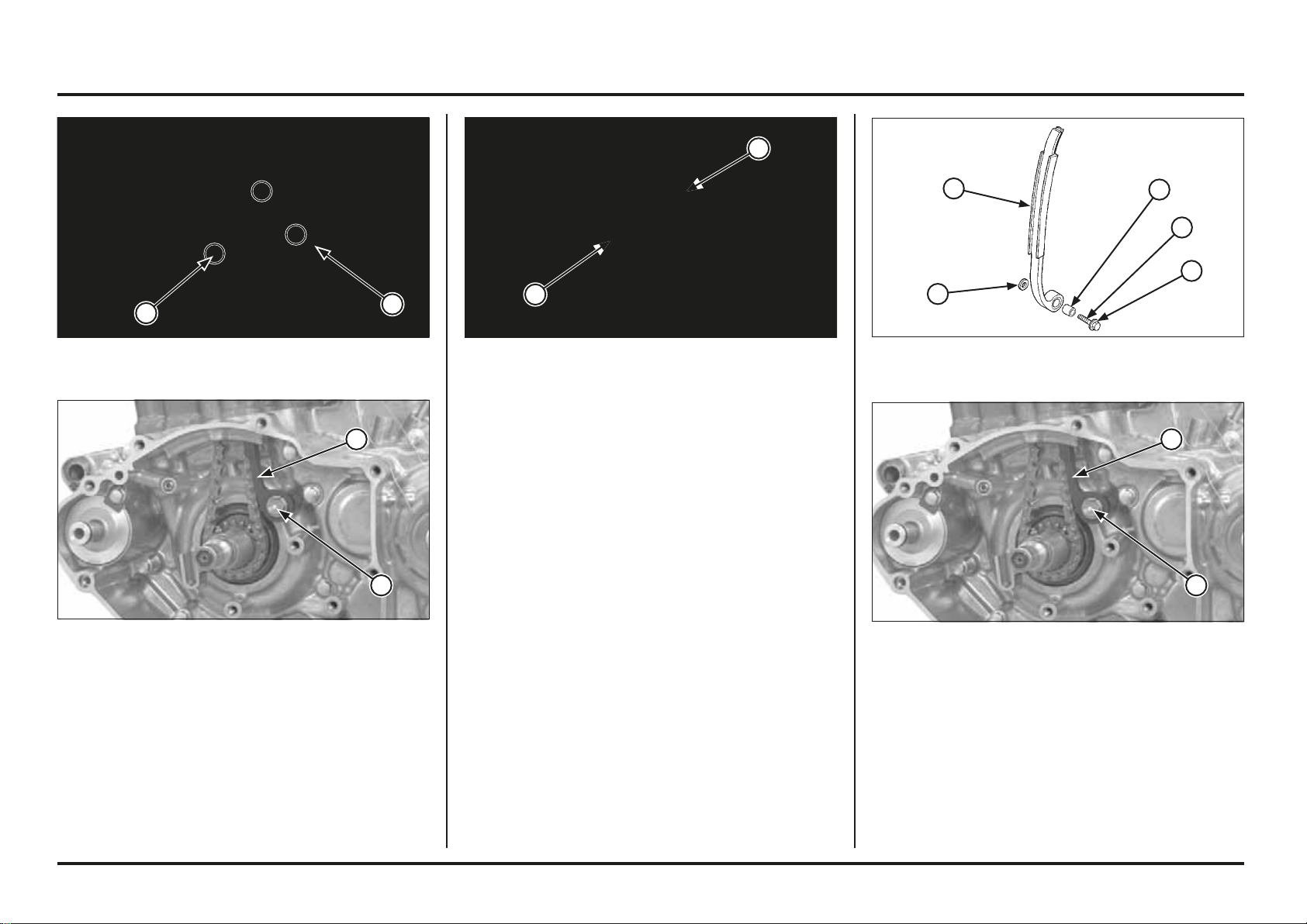
Engine servicing
4-24
4-24
(1) CAM CHAIN TENSIONER
(2) PIVOT BOLT
Installation
Apply a locking agent to the cam chain tensioner pivot
bolt thread.
Install the washer, cam chain tensioner, pivot collar and
pivot bolt.
Tighten the pivot bolt to the specified torque.
Torque: 12 N•m (1.2 kgf•m, 9 lbf•ft)
(1) WASHER (2) PIVOT COLLAR
(3) CAM CHAIN TENSIONER
(4) PIVOT BOLT (5) APPLY LOCKING AGENT
Inspection
Inspect the cam chain tensioner and cam chain guide for
excessive wear or damage, replace if necessary.
(1) CAM CHAIN TENSIONER
(2) CAM CHAIN GUIDE
(1) BOLT
(2) CAM CHAIN TENSIONER
Remove the following:
– Cylinder head (page 4-23)
– Left crankcase cover (page 4-49)
– Flywheel (page 4-52)
Remove the bolts and cam chain guide plate.
Remove the bolt, cam chain tensioner, pivot collar and
washer.
(1) BOLTS
(2) CAM CHAIN GUIDE PLATE
2
1
2
1
5
4
3
2
1
2
1
1
2
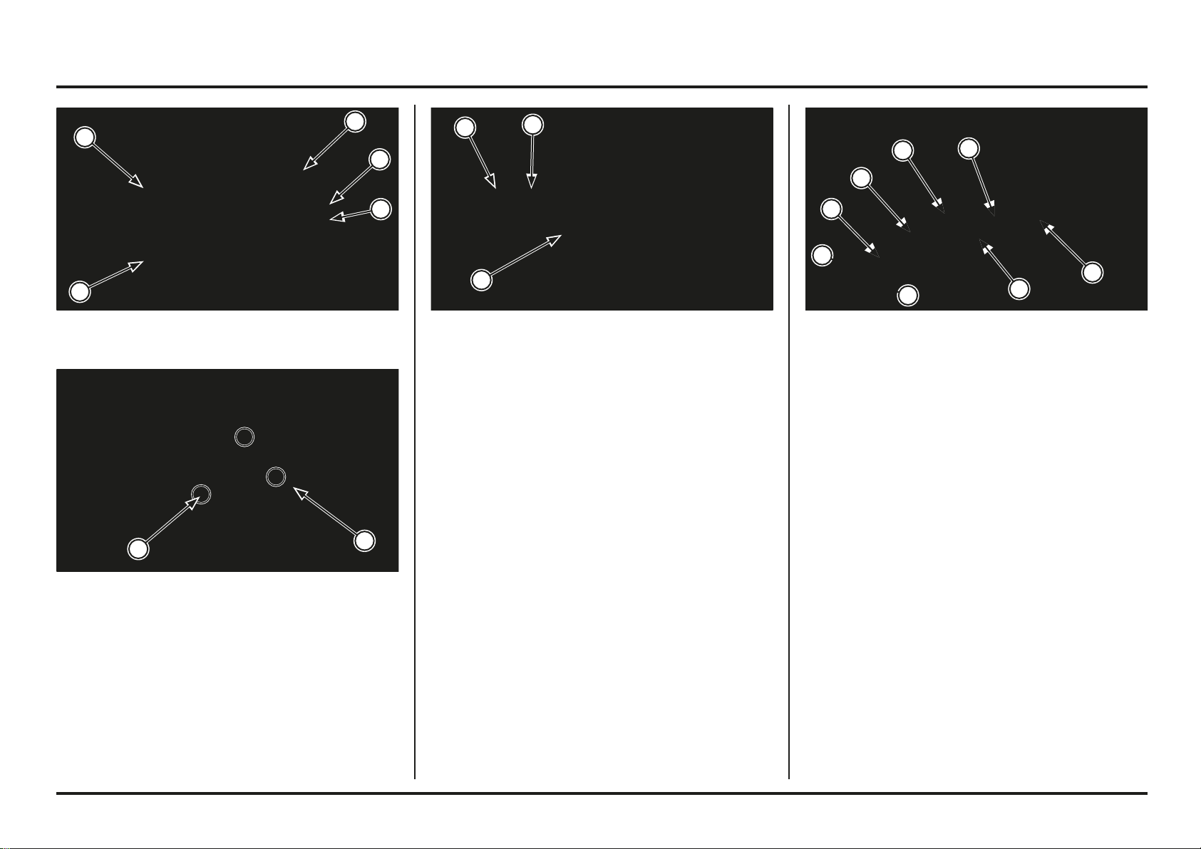
Engine servicing
4-25
4-25
(1) RETAINER
(2) OUTER SPRING
(3) INNER SPRING
(4) SPRING SEAT
(5) VALVE
(6) STEM SEAL
(7) COTTERS
Remove the following:
– Spring retainer
– Outer and inner valve springs
– Stem seal
– Valve spring seat
– Intake and exhaust valve
Cylinder Head Disassembly
Remove the cylinder head (page 4-23).
Remove the valve spring cotters using the special tools.
To prevent loss of tension, do not compress the valve
springs more than necessary to remove the cotters.
Tools:
Valve spring compressor 07757-0010000
Compressor attachment 07959-KM30101
(1) VALVE SPRING COMPRESSOR
(2) ATTACHMENT
(3) COTTERS
(1) CAM CHAIN GUIDE PLATE
(2) BOLTS
Install the cam chain guide by aligning the guide end with
the groove in the crankcase and the tab with the groove
in the cylinder.
Install the cam chain guide plate and tighten the bolts.
Install the following:
– Flywheel (page 4-53)
– Left crankcase cover (page 4-50)
– Cylinder head (page 4-37)
(1) CAM CHAIN GUIDE
(2) ALIGN
1
2
2
1
2
2
1
2
1
6
5
4
3
2
1
3
7
7
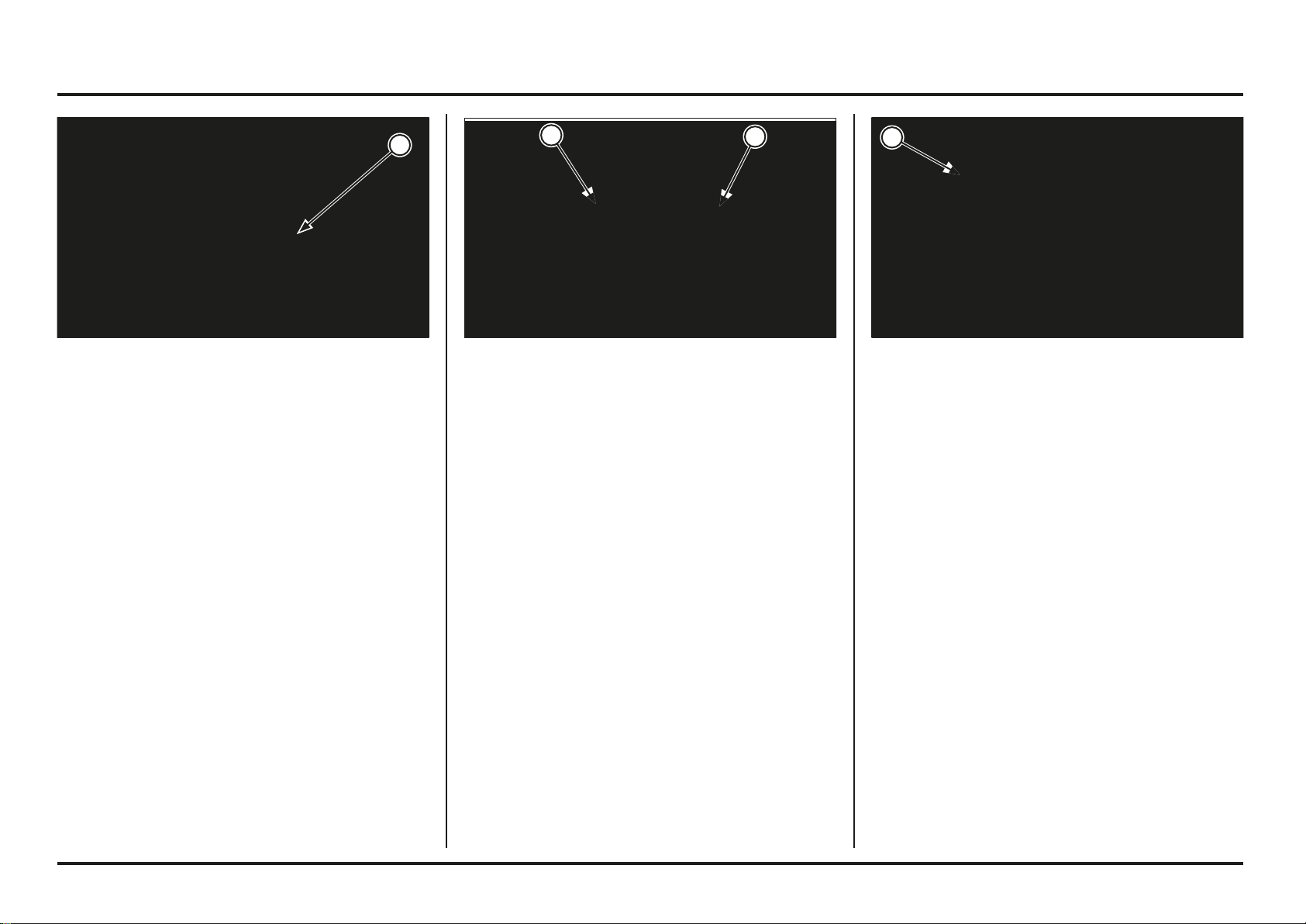
Engine servicing
4-26
4-26
Valve/Valve Guide
Inspect each valve for out-of-round, burns, scratches or
abnormal stem wear.
Check the valve movement in the guide.
Measure and record the valve stem O.D.
Service limits:
IN: 4.470 mm (0.1760 in)
EX: 4.460 mm (0.1756 in)
(1) VALVE
Valve spring
Check the valve springs for fatigue or damage.
Measure the free length of the intake and exhaust valve
springs.
Service limits:
Inner: 24.9 mm (0.98 in)
Outer: 27.6 mm (1.09 in)
(1) OUTER VALVE SPRING
(2) INNER VALVE SPRING
Cylinder Head Inspection
Cylinder Head
Remove the carbon deposits from the combustion
chamber or exhaust port.
Use care not to scratch the combustion chamber or the
head gasket surface.
Check the spark plug hole and valve area for cranks.
Check the cylinder head for warpage with a straight edge
and feeler gauge.
Service limit: 0.05 mm (0.002 in)
(1) COMBUSTION CHAMBER
1
1
1
2
Engine servicing
4-27
4-27
Valve Guide Replacement
Mark new valve guides at the proper depth (see
specification; page 2-1) using a marker.
Chill the new valve guides in a freezer for about 1 hour.
Heat the cylinder head to 100 – 150 ˚C (212 – 300 ˚F)
with a hot plate or oven.
Do not heat the cylinder head beyond 180 ˚C (320 ˚F).
Use temperature indicator sticks, available from welding
supply stores, to be sure the cylinder head is heated to
the proper temperature.
Use a torch to heat the cylinder head may cause warpage.
Support the cylinder head and drive the valve guides out
of the cylinder head from the combustion chamber side.
Tool:
Valve guide driver 07HMD–ML00101
(1) VALVE GUIDE DRIVER
Measure and record the valve guide I.D. using a ball gauge
or inside micrometer.
Service limit:
IN/EX: 4.552 mm (0.1792 in)
Subtract each valve stem O.D. from the corresponding
guide I.D. to obtain the stem-to-guide clearance.
Standard:
IN: 0.010 – 0.037 mm (0.0004 – 0.0015 in)
EX: 0.020 – 0.047 mm (0.0008 – 0.0019 in)
If the stem-to-guide clearance exceeds the service limits,
determine if a new guide with standard dimensions would
bring the clearance within tolerance.
If so, replace the guides as necessary and ream to fit.
Reface the valve seats whenever the valve guides are
replaced (page 4-28).
If the stem-to-guide clearance exceeds the service limits
with new guides also, replace the valves and guides.
Ream the valve guide to remove any carbon build-up
before measuring the guide.
Insert the reamer from the combustion chamber side of
the head and always rotate the reamer clockwise.
Tool:
Valve guide reamer, 4.508 mm 07HMH–ML00101
(1) VALVE GUIDE REAMER
1
1
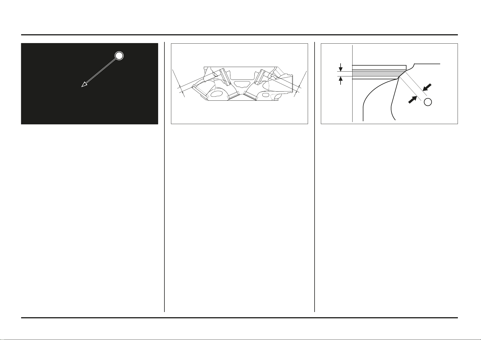
Engine servicing
4-28
4-28
Valve Seat Inspection/Refacing
Clean the intake and exhaust valves thoroughly to remove
carbon deposits.
Apply a light coating of Prussian Blue to the valve seat.
Tap the valves and seats using a rubber hose or other
hand lapping tool.
Remove the valve and inspect the valve seat face.
The valve seat contact should be within the specified
width and even all around the circumference.
Standard:
IN/EX: 0.9 – 1.1 mm (0.035 – 0.043 in)
Service limit:
IN/EX: 1.7 mm (0.07 in)
If the seat width is not within specification, reface the
valve seat (page 4-29).
Inspect the valve seat face for:
Uneven seat width:
– Replace the valve and reface the valve seat.
Damaged face:
– Replace the valve and reface the valve seat.
(1) VALVE SEAT WIDTH
Check that the valve guides are at the proper depth using
a slide caliper, adjust the height if necessary.
Specified depth:
IN: 8.0 – 8.3 mm (0.31 – 0.33 in)
EX: 8.2 – 8.5 mm (0.32 – 0.33 in)
Let the cylinder head cool to room temperature.
Ream the new valve guides.
Insert the reamer from the combustion chamber side of
the cylinder head and always rotate the reamer clockwise.
Use cutting oil on the reamer during this operation.
Take care not to tilt or lean the reamer in the guide while
reaming.
Tool:
Valve guide reamer, 4.508 mm 07HMH–ML00101
Clean the cylinder head thoroughly to remove any metal
particles after reaming and reface the valve seats.
Remove the guide from the freezer.
While the cylinder head is still heated, drive new valve
guides into the cylinder head from the top of the cylinder
(camshaft side).
Drive the guides until the marks are parallel with the
cylinder head.
Tool:
Valve guide driver 07HMD–ML00101
(1) VALVE GUIDE DRIVER
1
1
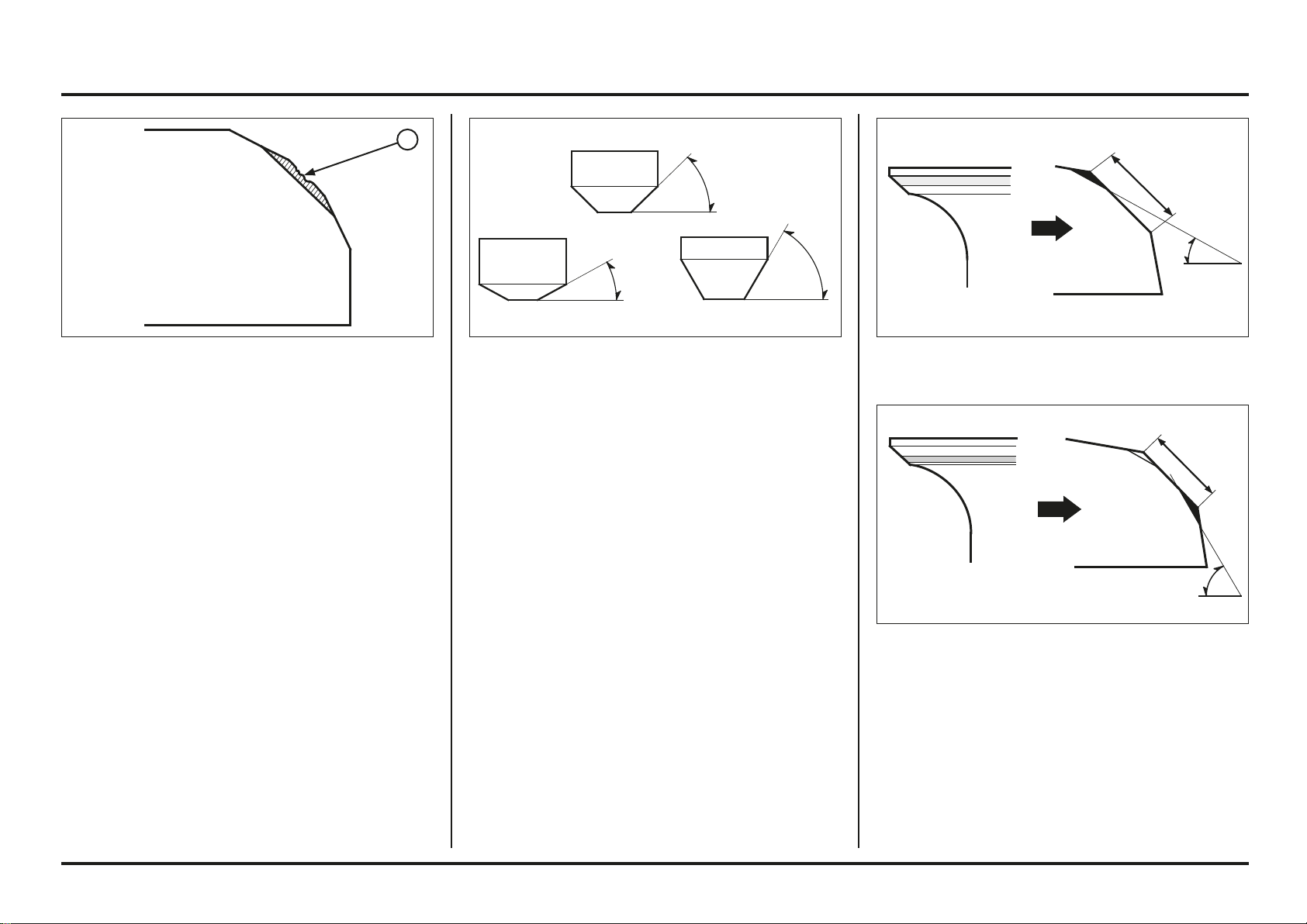
Engine servicing
4-29
4-29
If the contact area is too high on the valve, the seat must
be lowered using a 32˚ flat cutter.
If the contact area is too lower on the valve, the seat
must be raised using a 60˚ interior cutter.
Valve Seat Refacing
Valve seat cutters.grinders or equivalent valve seat
refacing equipment are recommended to correct worn
valve seat.
Follow the refacing manufacturer’s instructions.
Contact area (too high or too low)
– Reface the valve seat.
The valves cannot be ground, If a valve face is burned
or badly worn or if it contacts the seat unevenly, replace
the valve.
(1) ROUGHNESS
60º
1
45º
32º
32º
60º

Engine servicing
4-30
4-30
Use a interior cutter, remove 1/4 of the existing valve
seat material.
Tools:
Interior cutter, 26 mm 07780-0014500
Interior cutter, 22 mm 07780-0014202
Cutter holder, 4.5 mm 07781-0010600
or equivalent commercially available
Use a 32˚ flat cutter, remove 1/4 of the existing valve
seat material.
Tools:
Flat cutter, 25 mm 07780-0012000
Flat cutter, 21.5 mm 07780-0012800
Cutter holder, 4.5 mm 07781-0010600
or equivalent commercially available
Use a 45˚ cutter, remove any roughness or irregularities
from the seat.
Reface the seat with a 45˚ cutter whenever a valve guide
is replaced.
Tools:
Seat cutter, 24.5 mm 07780-0010100
Seat cutter, 22 mm 07780-0010701
Cutter holder, 4.5 mm 07781-0010600
or equivalent commercially available
(1) SEAT WIDTH
45º
32º
60º
1
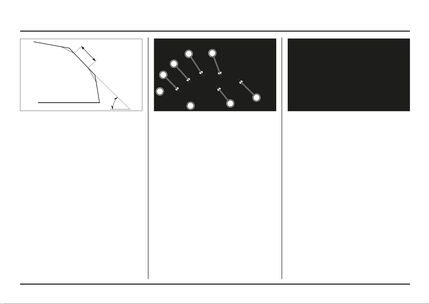
Engine servicing
4-31
4-31
(1) SPRING SEAT
(2) STEM SEAL
(3) VALVE
(4) INNER SPRING
(5) OUTER SPRING
(6) RETAINER
(7) COTTERS
Cylinder Head Assembly
Blow out all oil passages in the cylinder head with
compressed air.
Install the spring seat and new stem seal.
Lubricate the valve stem sliding surface with molybdenum
solution.
Insert the valves into the guide while turning it slowly to
avoid damage to the stem seal.
Using a 45˚ seat cutter, cut the seat to proper width.
Make sure all pitting and irregularities are removed.
Refinish if necessary.
After refacing, wash the cylinder head and valves.
After cutting the seats, apply lapping compound to the
valve face, and lap the valve using light pressure.
After lapping, wash any residual compound off the
cylinder head and valve.
Install the valve springs with the tightly wound coils
facing the combustion chamber.
Install the spring retainers.
45º
2
3
1
4
5
6
7
7
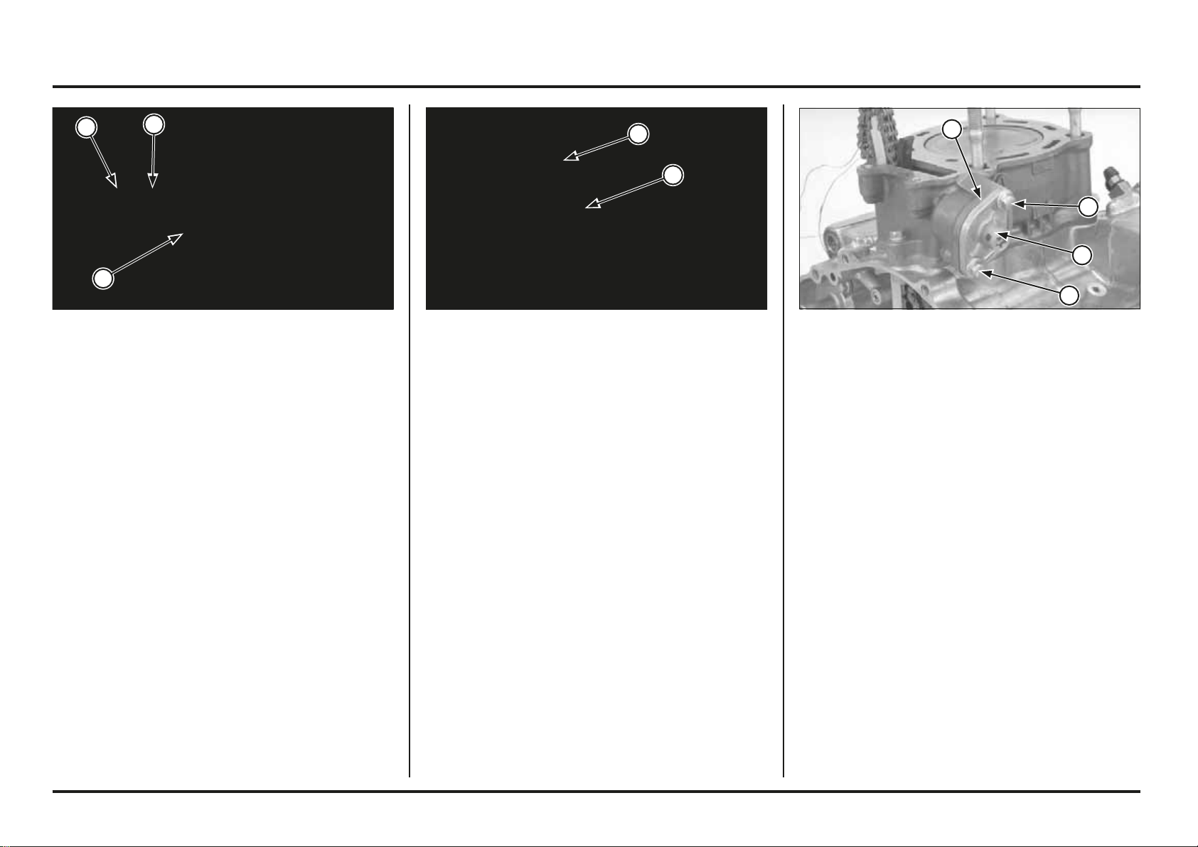
Engine servicing
4-32
4-32
(1) VALVE SPRING COMPRESSOR
(2) ATTACHMENT
(3) COTTERS
(1) PLASTIC HAMMERS (1) BOLTS
(2) CAM CHAIN TENSIONER LIFTER
(3) GASKET
Compress the valve springs with the special tools and
install the cotters.
Grease the cotters to ease installation.
Tools:
Valve spring compressor 07757-0010000
Compressor attachment 07959-KM30101
To prevent loss of tension, do not compress the valve
springs more than necessary.
Tap the valve stems gently with two plastic hammers as
shown to seat the cotters firmly.
Support the cylinder head so the valve heads do not
contact anything that may damage them.
Cylinder/Piston
Cylinder Removal
Remove the cylinder head (page 4-23).
Remove the bolts, cam chain tensioner lifter and gasket.
2
1
1
1
2
1
1
3
3
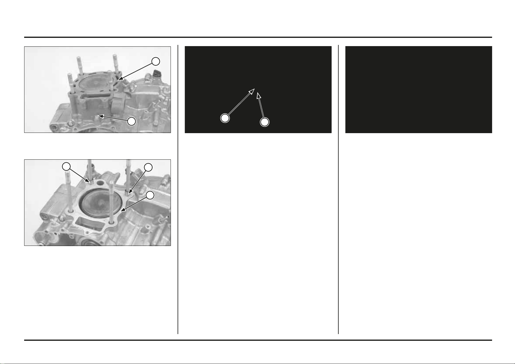
Engine servicing
4-33
4-33
(1) SEALING BOLT/SEALING WASHER
(2) CYLINDER
(1) PISTON PIN CLIP
(2) PISTON PIN
Piston Removal
Place a clean shop towel over the crankcase to prevent
the clip from falling the crankcase.
Remove the piston pin clips with pliers.
Press the piston pin out of the piston and remove the
piston.
Spread the piston rings and remove them by lifting up at
a point just opposite the gap.
Piston rings are easily broken; take care not to damage
them during removal.
(1) GASKET
(2) DOWEL PINS
Remove the mounting sealing bolt, sealing washer and
cylinder.
Remove the gasket and dowel pins.
2
1
2
2
1
2
1
Engine servicing
4-34
4-34
Inspection
Cylinder
Inspect the cylinder bore for wear or damage.
Measure the cylinder I.D. in the X and Y axis at three
levels.
Take the maximum reading to determine the cylinder
wear.
Service limit: 81.545 mm (3.2104 in)
Calculate the taper and out-of-round at three levels in the
X and Y axis. Take maximum reading to determine the
cylinder condition.
Service limit:
Taper: 0.05 mm (0.002 in)
Out-of-round: 0.05 mm (0.002 in)
Inspect the top of the cylinder for warpage.
Service limit: 0.05 mm (0.002 in)
Piston/Piston Ring
Remove the carbon deposits from the piston head or
piston ring grooves using old piston rings.
Inspect the piston for damage and the ring grooves for
wear.
Temporarily install the piston rings to their proper position
with the mark facing up.
Measure the piston ring groove clearance with the rings
pushed into the grooves.
Service limit:
Top: 0.125 mm (0.0049 in)
Second: 0.075 mm (0.0003 in)
Inspect the piston ring grooves for wear or damage.
Engine servicing
4-35
4-35
Measure the O.D. of the piston at 3.0 mm (0,0118 in)
from bottom of skirt and 90 degrees to the piston pin
hole.
Service limit: 81.455 mm (3.2069 in)
If the O.D. is under the service limit, replace the piston
with a new one.
Calculate the piston-to-cylinder clearance.
Service limit: 0.18 mm (0.007 in)
Measure the piston pin bore I.D.
Service limit: 16.03 mm (0.631 in)
Check the piston pin for wear or excessive discoloration.
Measure the piston pin O.D.
Service limit: 15.98 mm (0.629 in)
Replace the piston pin if necessary.
Calculate the piston pin-to-piston clearance.
Service limit: 0.04 mm (0.002 in)
Insert each piston ring into the cylinder and measure the
ring end gap.
Push the ring into the cylinder with the top of the piston
to be sure the ring is squarely in the cylinder.
Service limit:
Top: 0.44 mm (0,017 in)
Second: 0.64 mm (0.025 in)
Oil (side rail): 0.90 mm (0.035 in)
Connecting Rod
Measure the connecting rod small end I.D.
Service limit: 16.04 mm (0.631 in)
If the I.D. is not over the service limit, replace the piston
pin.
If the I.D. is over the service limit, replace the crankshaft
(page 4-54).
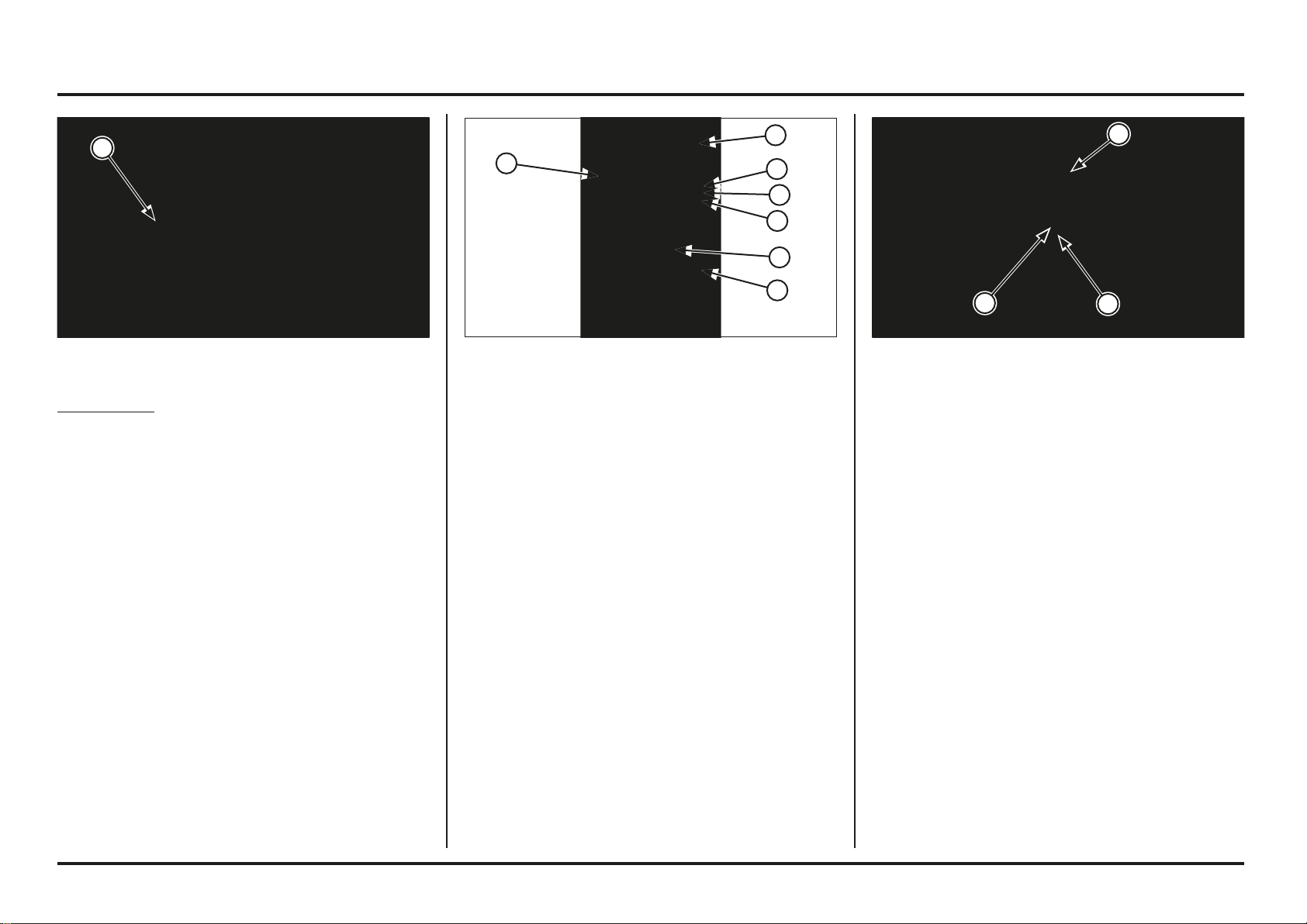
Engine servicing
4-36
4-36
(1) TENSIONER LIFTER (1) TOP RING (SILVER)
(2) SECOND RING (BLACK)
(3) OIL RINGS
(4) SPACER
(5) INDENTS
Piston Ring Installation
Clean the piston ring grooves thoroughly.
Apply engine oil to the piston rings and piston ring
grooves.
Install the piston ring into the grooves with their marking
“R” facing up (top ring and second ring.
Do not damage the piston ring by spreading the ends
too far.
Be careful not to damage the piston during piston ring
installation.
Do not align the oil ring (side rail) gaps.
Space the piston ring end 120 degrees apart.
After installation, the rings should rotate freely in the ring
grooves.
(1) INDENTS
(2) PISTON PIN
(3) NEW PISTON PIN CLIP
Tensioner lifter
Check the tensioner lifter operation as follows:
– The tensioner shaft should not go into the body when
it is pushed.
– When it is turned clockwise with a screwdriver, the
tensioner shaft should be pulled into the body. The
shaft should spring out of the body as soon as the
screwdriver is released.
Piston Installation
Place a shop towel over the cylinder opening to prevent
dust or dirt from entering the engine.
Clean any gasket material from the cylinder mating
surfaces of the crankcase.
Apply molybdenum oil solution to the connecting rod
small end.
Place a shop towel around the piston skirt and in the
crankcase to prevent the piston pin clips from falling into
the crankcase.
Apply engine oil to the piston pin outer surface and piston
pin bore of the piston.
Install the piston with the arrow facing intake side.
Install the piston pin and new piston pin clips.
Be careful not to drop the piston pin clip into the crankcase.
Always use new piston pin clips. Reinstalling used piston
pin clips may lead to serious engine damage.
Do not align the piston pin clip end gap with the piston
cut-out.
1
4
5
3
3
5
2
1
3
2
1
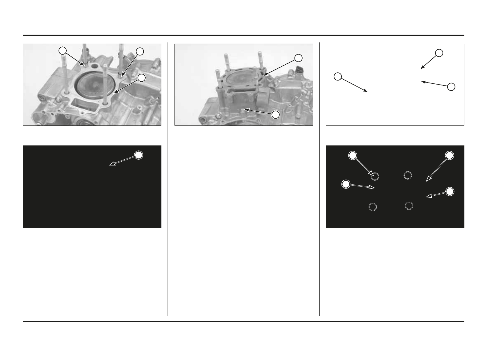
Engine servicing
4-37
4-37
(1) CYLINDER HEAD
(2) WASHERS/NUTS
(3) BOLTS
Cylinder Head Installation
Install the dowel pins and new gasket.
Install the cylinder head onto the cylinder.
Apply oil to the cylinder head mounting nut threads and
seating surface, install them with washers.
Install the two cylinder head 6 mm bolts.
Tighten the cylinder head nuts (cap nuts on right side) in
a crisscross pattern in 2 – 3 steps to the specified torque.
Torque: 39 N•m (4.0 kgf•m, 29 lbf•ft)
(1) DOWEL PINS
(2) NEW GASKET
Apply locking agent to the cylinder mounting sealing bolt
threads.
Install the cylinder mounting sealing bolt with a new
sealing washer but do not tighten it yet.
(1) CYLINDER
(2) NEW SEALING BOLT/SEALING WASHER
(1) CYLINDER
Cylinder Installation
Install the dowel pins and new gasket.
Coat the cylinder bore, piston and piston rings with clean
engine oil and install the cylinder while compressing the
piston rings being careful not to damage the rings.
(1) DOWEL PINS
(2) NEW GASKET
1
2
3
2
1
1
2
2
1
1
1
1
2
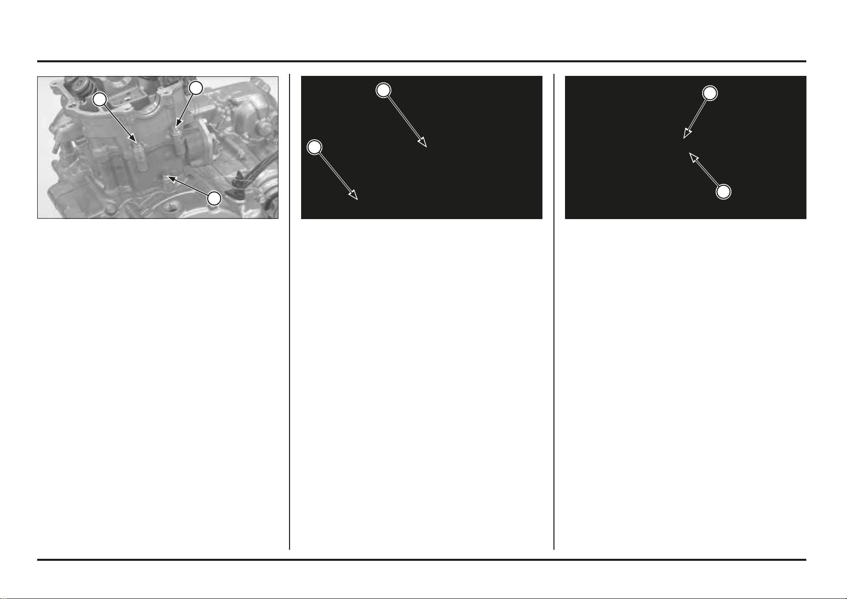
Engine servicing
4-38
4-38
Camshaft/Cylinder Head Cover Installation
Camshaft Installation
Turn the crankshaft by operating the kickstarter, align the
“T” mark on the flywheel with the index mark on the left
crankcase cover.
(1) “T” MARK
(2) INDEX MARK
Install the upper engine hanger bolt, tighten the nut to the
specified torque.
Torque: 24 N•m (2.4 kgf•m, 17 lbf•ft)
Connect the radiator hose to the water joint, tighten the
clamp screw securely.
Install the following:
– Camshaft
– Cylinder head cover
– Throttle body/insulator
– Exhaust pipe
Pour recommended coolant mixture and bleed air.
(1) HANGER BOLT
(2) RADIATOR HOSE
Tighten the cylinder sealing bolt and cylinder head
mounting bolts securely.
(1) CYLINDER HEAD BOLTS
(2) CYLINDER SEALING BOLT
2
1
2
1
1
2
1
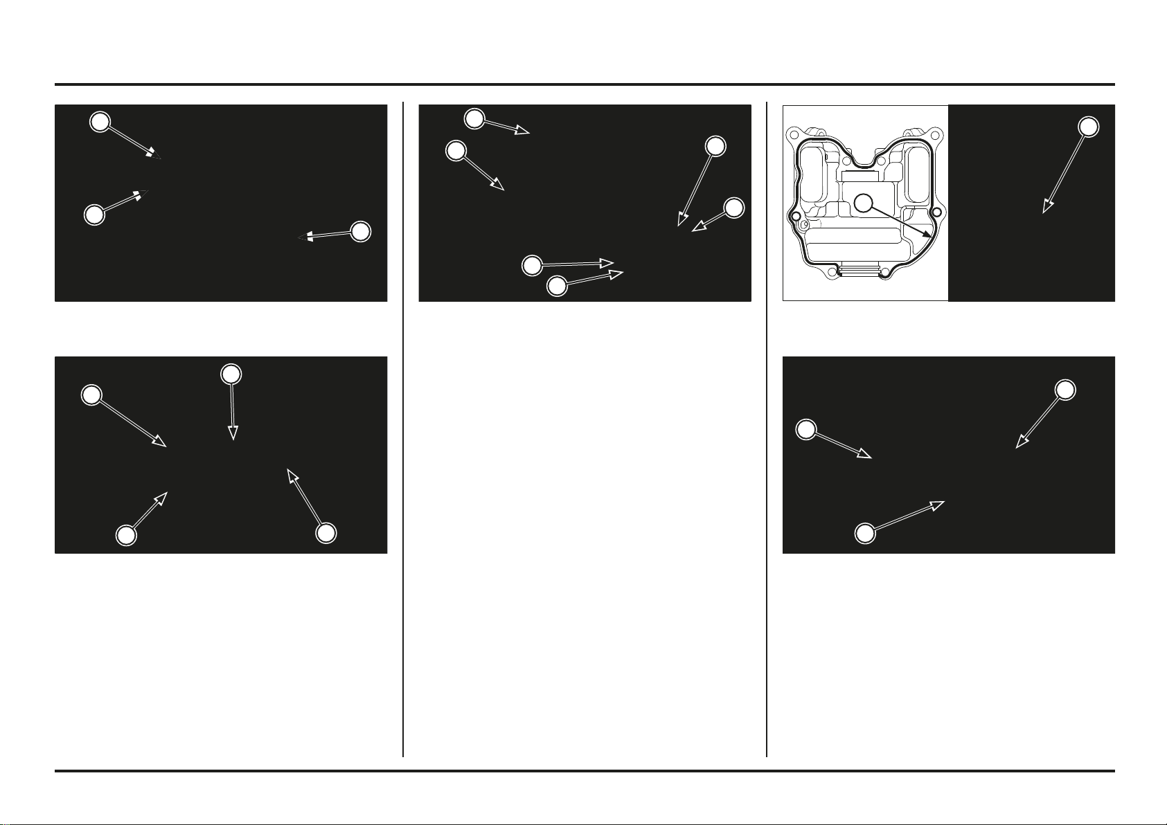
Engine servicing
4-39
4-39
(1) CAMSHAFT END CAP
(2) DOWEL PINS
Cylinder Head Cover Installation
Apply sealant to the mating surface of the cylinder head
cover.
Install the camshaft bearing retainer into the cylinder head
cover inner groove.
Install the camshaft end cap.
(1) APPLY SEALANT
(2) BEARING RETAINER
(1) NEW O-RINGS
(2) INTAKE ROCKER ARM SHAFT
(3) INTAKE ROCKER ARM
(4) EXHAUST ROCKER ARM
(5) EXHAUST ROCKER ARM SHAFT
Cylinder Head Cover Assembly
Apply molybdenum oil solution to the rocker arm I.D. and
rocker arm shaft sliding surface.
Install new O-ring to each rocker arm shaft groove.
Place the intake rocker and exhaust rocker arm into the
cylinder head cover.
The intake rocker arm is identified with groove on the end
of the shaft.
Install the intake and exhaust rocker arm shafts with their
cut-out facing in and the shaft end oil hole facing up as
shown.
(1) CAM SPROCKET
(2) CAM CHAIN
(3) INDEX MARKS
Apply molybdenum oil solution to the camshaft cam
surface.
Install the bearings both ends of the camshaft.
Install the left camshaft bearing with its groove side
facing out.
Install the cam chain onto the cam sprocket, then install
the camshaft onto the cylinder head while aligning the
index marks on the cam sprocket with the upper surface
of the cylinder head.
(1) BEARINGS
(2) GROOVE
1
2
1
5
4
3
2
1
1
2
1
2
1
2
2
1
3
3
Engine servicing
4-40
4-40
(1) RADIATOR HOSE
(2) KICKSTARTER PEDAL
(3) BOLTS
(4) CLUTCH COVER
(5) RIGHT CRANKCASE COVER
Right Crankcase Cover
Removal
Remove the water pump cover (page 4-15).
Remove the bolt and kickstarter pedal.
Squeeze the clutch lever and secure the lever to prevent
the clutch slave piston comes out from the clutch cover.
Disconnect the lower radiator hose.
Remove the bolts, clutch cover, right crankcase cover,
gasket and dowel pins.
(1) “UP” MARK
(2) TAPPET ADJUSTING HOLE CAP
(3) BOLTS
Check the valve clearance (page 3-4).
Install new O-rings into the tappet adjusting hole cover
grooves.
Install the tappet adjusting hole cap with their “UP” marks
facing up.
Install and tighten the cover bolts securely.
Connect the crankcase breather hose to the cylinder head
cover.
(1) TAPPET ADJUSTING HOLE CAP (2) O-RING(1) CYLINDER HEAD COVER
(2) NEW SEALING WASHERS/6 MM BOLTS
(3) NEW SEALING WASHERS
(4) SH BOLTS
Install the cylinder head cover.
Install new sealing washers and 6 mm bolts.
Install the two new sealing washers and cylinder head
cover SH bolts.
Tighten the cylinder head cover bolts securely.
1
3
3
4
2
2
2
1
5
4
3
2
1
2
3 3
1
Engine servicing
4-41
4-41
(1) DOWEL PINS
(2) NEW GASKET
(1) RIGHT CRANKCASE COVER
(2) CLUTCH COVER
(3) WATER PUMP COVER
(4) BOLTS
(5) RADIATOR HOSE
(6) KICKSTARTER PEDAL
Install the right crankcase cover while turning the water
pump impeller.
Check the clutch cover O-ring is in good condition, replace
if necessary.
Install the clutch cover.
Install the water pump cover (page 4-15).
Tighten the right crankcase cover bolts in a crisscross
pattern in 2 – 3 steps.
Install the kickstarter pedal and tighten the bolt to the
specified torque.
Torque: 37 N•m (3.8 kgf•m, 27.4 lbf•ft)
Connect the lower radiator hose.
Fill the crankcase with recommended transmission oil
(page 3-8).
Fill the coolant and bleed air.
(1) OIL BOLT
(2) SEALING WASHERS
Installation
Install two dowel pins and new gasket onto the crankcase.
(1) BOLTS
(2) CLUTCH COVER
Clutch Slave Cylinder
Drain the clutch fluid from the clutch hydraulic system.
Remove the oil bolt, sealing washers and clutch hose
eyelet.
Remove the bolts, clutch cover and O-ring.
Remove the dowel pins.
1
1
2
1
1
2
2
4
6
5
3
3
22
2
1
Engine servicing
4-42
4-42
(1) SLAVE CYLINDER PISTON
(2) SPRING
(3) O-RING (BLACK)
(4) O-RING (GREEN)
Apply small squirts of air pressure to the fluid inlet to
remove the piston.
Do not use high pressure air or bring the nozzle close to
the inlet.
Remove the slave cylinder piston, return spring and
O-rings.
Remove the O-rings from the piston.
Check the slave cylinder in the clutch cover for scoring or
other damage.
Check the slave cylinder piston for scratches, scoring or
other damage.
Check the piston spring for weakness or damage.
Clean slave cylinder O-ring grooves with clean brake fluid.
Apply silicone grease to the O-rings.
Install 23 x 2.1 mm O-ring (Black) into the spring side
groove.
Install 21.8 x 2.4 mm O-ring (Green) into the lifter plate
side groove.
Do not interchange the O-rings.
Install the return spring and piston into the slave cylinder
in the clutch cover.
(1) O-RING
(2) DOWEL PINS
(3) CLUTCH COVER
(1) SEALING WASHERS
(2) OIL BOLT
(1) CLUTCH COVER
(2) BOLTS
Install new O-ring into the clutch cover groove.
Install the dowel pins onto the right crankcase cover.
Install the clutch cover onto the right crankcase cover.
Install and tighten the clutch cover bolts.
Install the clutch hose eyelet with new sealing washers.
Install and tighten the oil bolt..
Fill the clutch system with recommended brake fluid and
bleed air.
2
1
21
1
2
4
3
2
1
3
2
2
1
Engine servicing
4-43
4-43
(1) CLUTCH LIFTER PIECE ASSEMBLY
(2) LIFTER PLATE BOLTS
(3) LIFTER PLATE
(4) CLUTCH SPRINGS
Clutch
Removal
Pull the clutch lever and hold it with a suitable clamp.
Remove the bolts and clutch cover without disconnecting
the clutch fluid line.
Remove the clutch lifter piece assembly.
Remove the following:
– Clutch lifter plate bolts
– Lifter plate
– Clutch springs
– Spring base washers
(1) CLUTCH CENTER HOLDER (1) CLUTCH CENTER (2) CLUTCH DISCS
(3) CLUTCH PLATE (4) PRESSURE PLATE
(5) PAPER DISCS
(1) LOCK WASHER
(2) PLAIN WASHER
(3) SPRING BASE WASHER
Hold the clutch assembly with the clutch center holder
and remove the clutch center nut.
Tool:
Clutch center holder 07JMB-
MN50302
Remove the lock washer, flat washer, springs and six
spring base washers.
(1) THRUST WASHER
(2) CLUTCH OUTER
(3) NEEDLE BEARING
(4) CLUTCH OUTER GUIDE
Remove the following:
– Clutch center
– Six clutch discs
– Five clutch plates
– Clutch pressure plate
Remove the thrust washer, clutch outer, needle bearing
and clutch outer guide.
4
3
2
2
1
5
2
3
2
1
4
3
2
1
1
2
1
4
3
Engine servicing
4-44
4-44
(1) CLUTCH CENTER
(2) CLUTCH OUTER
(3) OUTER GUIDE
(4) NEEDLE BEARING
Inspection
Check the following items (page 2-2).
Clutch outer for wear, cracks or indentation by the
clutch discs.
Clutch center grooves for damage, crack or indentation
by the clutch plates.
Clutch outer needle bearing for wear or damage.
Clutch spring free length
Clutch disc thickness
Clutch plate warpage
Clutch outer I.D.
Clutch outer guide I.D. and O.D.
Clutch pressure plate for wear or damage
Mainshaft O.D. at clutch outer guide
(1) LIFTER PIECE ASSEMBLY (1) OUTER GUIDE
(2) NEEDLE BEARING
(1) CIRCLIP
(2) THRUST WASHER
(3) THRUST NEEDLE BEARING
(4) LIFTER PIECE
Check the lifter piece needle bearing by turning the thrust
washer with your finger.
If the bearing movement is not smooth, disassemble and
replace the bearing.
Remove the circlip, thrust washer and thrust needle
bearing from the lifter piece.
Assemble the lifter piece in the reverse order of removal.
(1) CLUTCH OUTER
(2) THRUST WASHER
Installation
Install the clutch outer guide and needle bearing onto the
mainshaft.
Install the clutch outer and thrust washer.
1
2
1
2
4
3
2
1
1
4
3
2
1
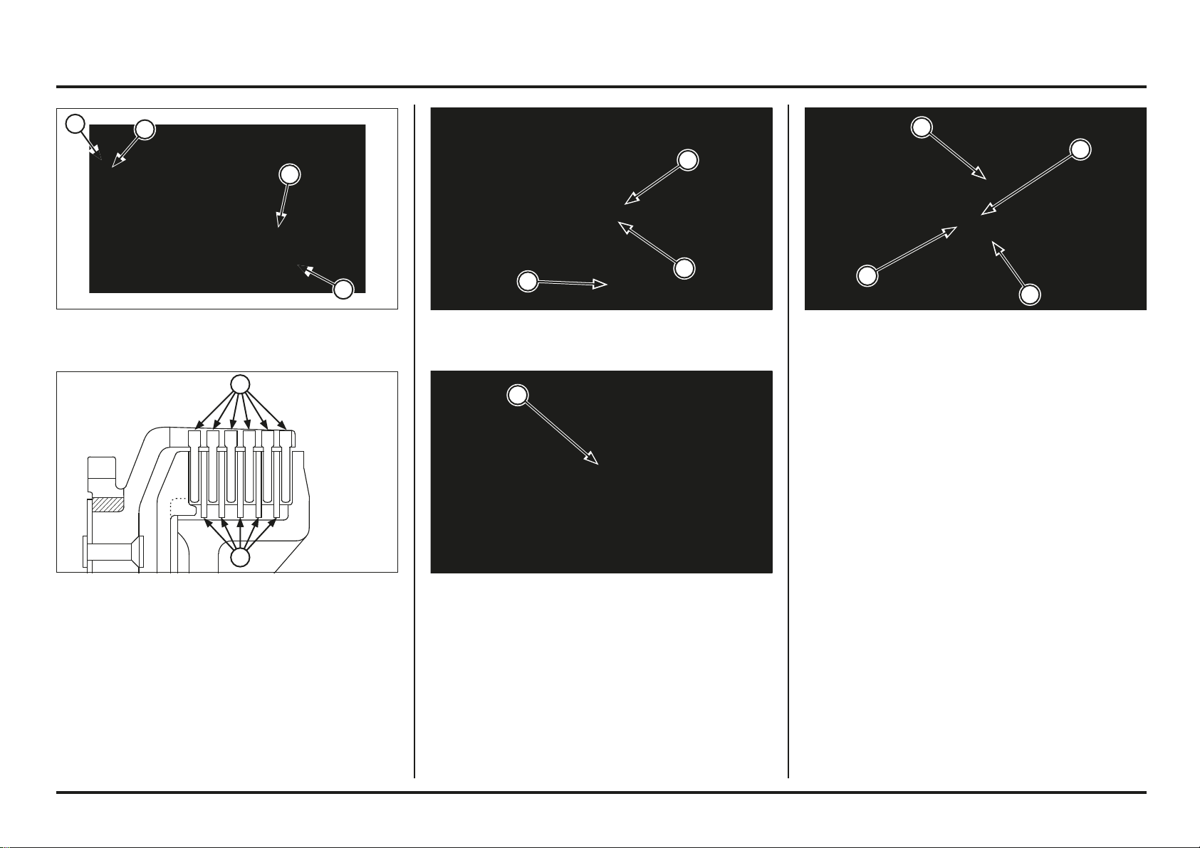
Engine servicing
4-45
4-45
(1) PRESSURE PLATE
(2) CLUTCH CENTER
(3) DOT MARKS
(1) THRUST WASHER
(2) LOCK WASHER (“OUTSIDE” MARK IN FRONT)
(3) SPRING BASE WASHER
(1) CLUTCH SPRINGS
(2) LIFTER PLATE
(3) BOLTS
(4) LIFTER PIECE ASSEMBLY
Install spring base washers, the clutch springs, lifter plate
and spring bolts.
Tighten the spring bolts in a crisscross pattern in several
steps, then tighten them to the specified torque.
Torque: 12 N•m (1.2 kgf•m, 9 lbf•ft)
Install the clutch lifter piece assembly.
Install the clutch cover (page 4-44).
(1) CLUTCH DISCS
(2) CLUTCH PLATE
Coat the clutch plates with clean transmission oil.
Install the clutch discs and plates alternately onto the
clutch center starting with the clutch disc
Install the clutch pressure plate onto the clutch center
aligning the dot mark on the pressure plate with the dot
marks on the clutch center as shown.
Install the clutch center assembly into the clutch outer.
(1) CLUTCH CENTER HOLDER
Install the thrust washer onto the mainshaft.
Install the lock washer with its “OUT SIDE” mark facing
out.
Apply oil to the clutch center nut and install it.
Hold the clutch assembly with the clutch center holder
and tighten the clutch center nut to the specified torque.
Tool:
Clutch center holder 07JMB-MN50302
Torque: 69 N•m (7.0 kgf•m, 51 lbf•ft)
1
1
2
1
3
3
2
1
2
3
4
1
2
3
Engine servicing
4-46
4-46
(1) IDLE GEAR/THRUST WASHER
(2) BOLT
(3) STOPPER PLATE
(4) KICKSTARTER ASSEMBLY
Kickstarter
Removal/Disassembly
Remove the clutch (page 4-43)
Remove the kickstarter idle gear and thrust washer.
Remove the bolt and return spring stopper plate.
Unhook the return spring end from the crankcase and
remove the kickstarter as an assembly.
Disassemble the kickstarter.
Inspection
Check the following items (page 2-2):
Return spring and ratchet spring for wear or damage.
Needle bearing for wear or damage.
Pinion gear I.D. and spindle O.D.
Idle gear I.D. and bushing O.D. and I.D.
Countershaft O.D. at the idle gear bushing.
(1) RATCHET SPRING (2) STARTER RATCHET
(3) PINION GEAR (4) SPINDLE
(5) RETURN SPRING (6) COLLAR
(1) RETURN SPRING
(2) COLLAR
(3) WASHER
Install the return spring with its end into the spindle hole.
Install the collar aligning its groove with the return spring
end, then install the washer.
(1) PINION GEAR (2) THRUST WASHER
(3) SNAP RING (4) STARTER RATCHET
(5) PUNCH MARKS (6) RATCHET SPRING
Assembly/Installation
Assemble the kickstarter as shown in the illustration
above.
Install the thrust washer, pinion gear, thrust washer and
snap ring.
Install the starter ratchet aligning the punch marks on the
ratchet and spindle.
Install the ratchet spring.
6
6
5
5
5
4
4
4
3
3
3
3
2
2
2
2
1
1
1
1
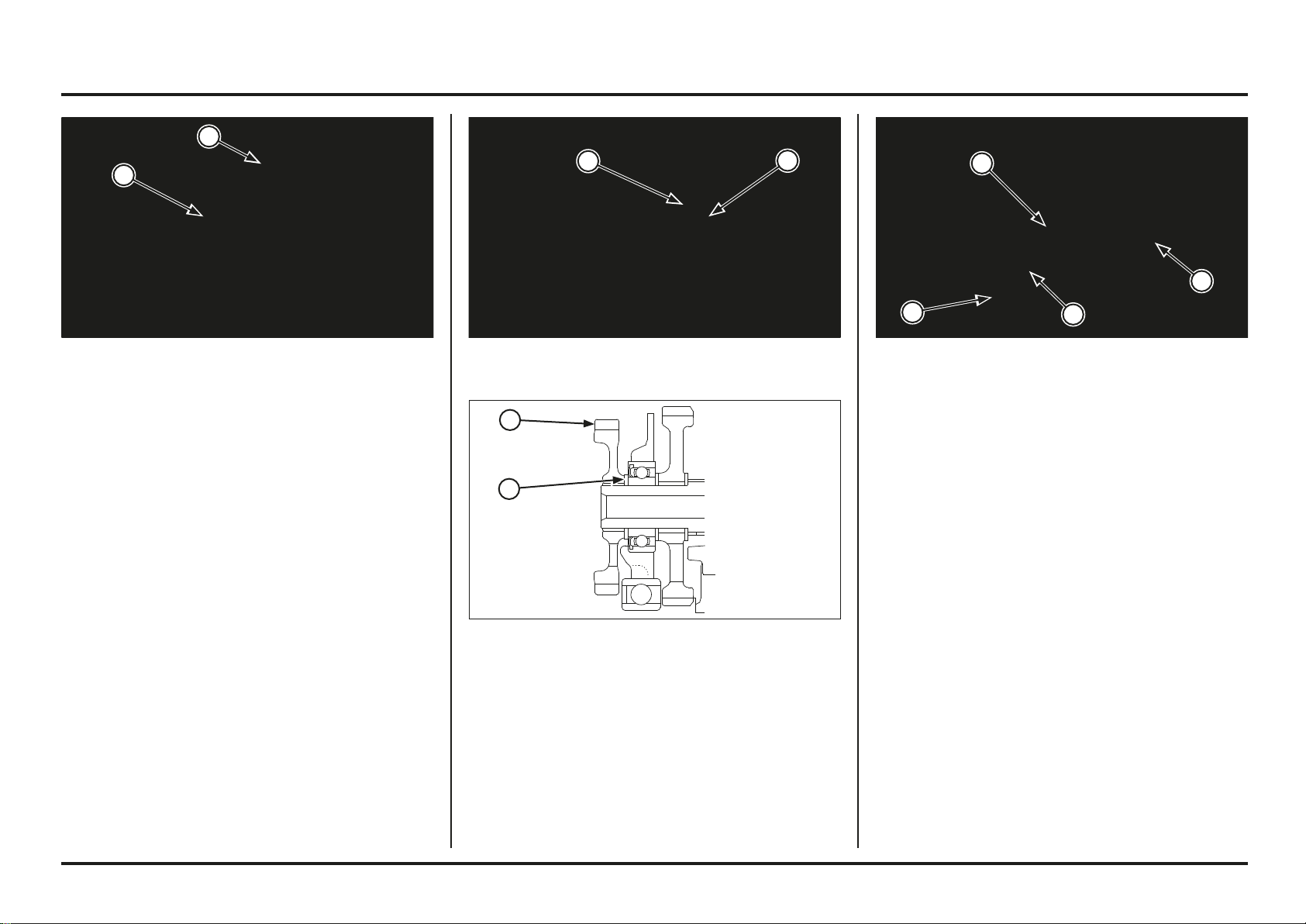
Engine servicing
4-47
4-47
(1) KICKSTARTER ASSEMBLY
(2) SPRING HOOK
(1) STOPPER PLATE
(2) BOLT
(1) GEARSHIFT SPINDLE
(2) BOLTS
(3) GUIDE PLATE
(1) THRUST WASHER
(2) IDLE GEAR
Install the kickstarter return spring stopper plate, and
tighten the bolt securely.
Install the thrust washer and idle gear onto the
countershaft.
Note the direction of the idle gear as shown in the
illustration.
Gearshift Linkage
Removal
Remove the gearshift pedal.
Pull out the gearshift spindle from the crankcase.
Remove the guide plate bolts and guide plate as an
assembly.
Remove the center bolt and drum center.
Remove the bolts and stopper arm, return spring and
washer.
Install the kickstarter assembly and hook the starter
ratchet with the stopper.
Install the return spring end into the crankcase hole as
shown.
1
2
2
1
3
2
2
1
2
1
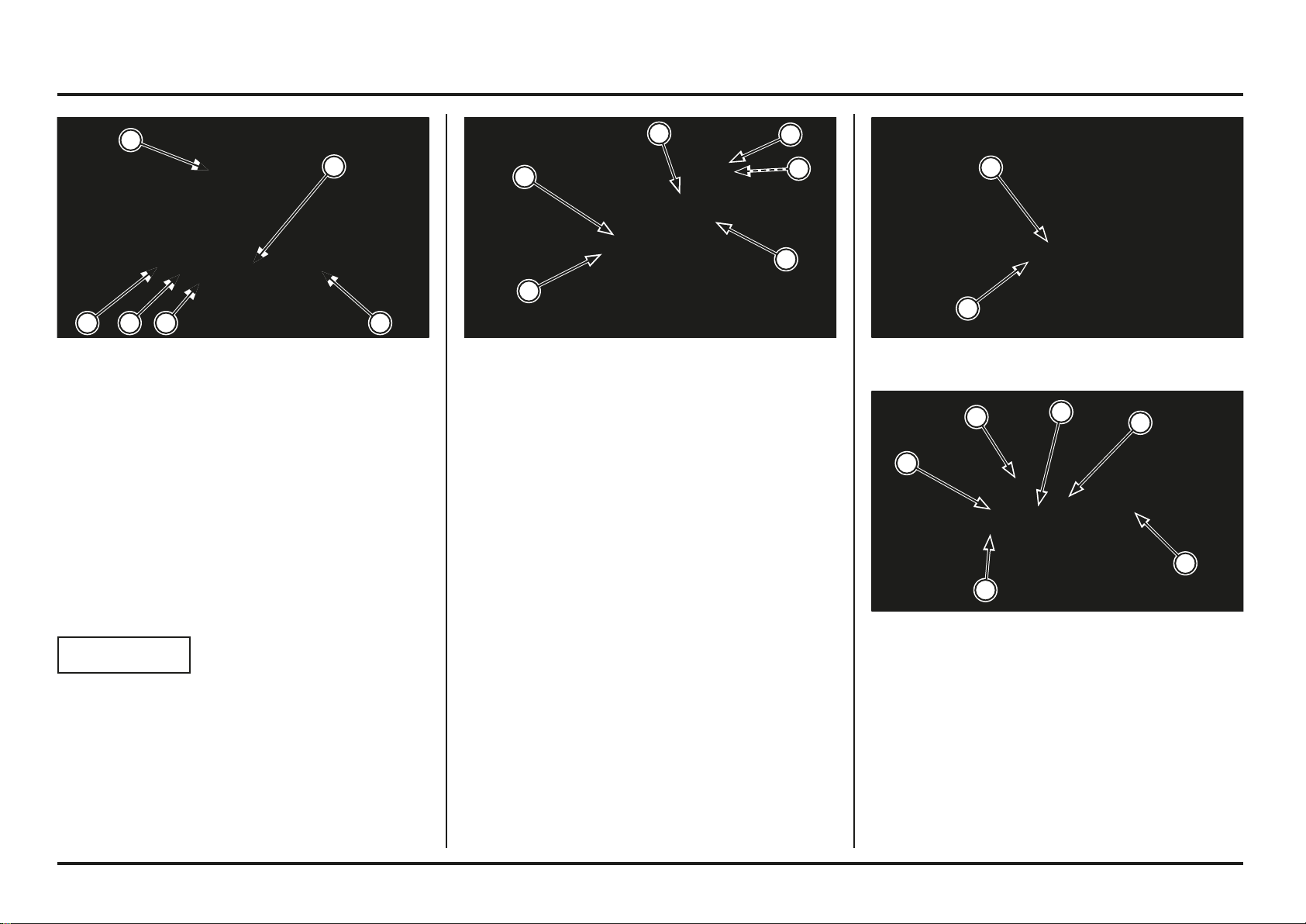
Engine servicing
4-48
4-48
(1) GUIDE PLATE (2) “UP” MARK
(3) BOLTS (4) DRUM SHIFTER
(5) SHIFTER COLLAR
Apply a locking agent to the center bolt threads and install
and tighten the drum center bolt to the specified torque.
Torque: 22 N•m (2.2 kgf•m, 16 lbf•ft)
Set the drum center in a position other than neutral.
Install the drum shifter with the guide plate while holding
onto the ratchet pawls.
Install the guide plate bolts and tighten them.
Install the shifter collar on the drum shifter.
(1) SHIFT DRUM CENTER
(2) CENTER PIN
(1) RETURN SPRING
(2) WASHER
(3) STOPPER ARM
(4) DRUM CENTER
(5) DOWEL PIN
(6) CUT-OUT
Install the return spring, plain washer and stopper arm
and tighten the stopper arm bolt to the specified torque.
Torque: 12 N•m (1.2 kgf•m, 9 lbf•ft)
Install the dowel pin into the shift drum.
Install the drum center by aligning the cut-out with the
dowel pin on the shift drum while holding the stopper arm
with the screwdriver as shown.
(1) DRUM SHIFTER
(2) SPRING
(3) PLUNGER
(4) RATCHET PAWL A
(5) RATCHET PAWL B
(6) GUIDE PLATE
Inspection
Inspect each part for wear or damage and replace if
necessary.
Installation
Apply transmission oil to the ratchet pawls, springs and
plungers.
Assemble the drum shifter, springs, plungers and ratchet
pawls in the guide plate as shown.
NOTICE
Note the direction of the ratchet pawl A and B.
54 3 2
1
6
6
5
4
3
2
1
2
1
5
4
3
3
2
1

Engine servicing
4-49
4-49
Remove the engine oil drain bolt and sealing washer, drain
the engine oil.
Remove the bolts and left crankcase cover.
NOTICE
The left crankcase cover (stator) is magnetically attached
to the fl ywheel, be careful during removal.
Remove the left crankcase cover, gasket and dowel pins.
(1) DRAIN BOLT/SEALING WASHER
(2) BOLTS
(3) LEFT CRANKCASE COVER
Left Crankcase Cover
Removal
Remove the skid plate and drain engine oil.
Disconnect the alternator 3P (Natural) connector and
ignition pulse generator 2P (Natural) connectors.
Remove the gearshift pedal.
(1) 3P (NATURAL) CONNECTOR
(2) 2P (NATURAL) CONNECTOR
(1) GEARSHIFT PEDAL
Install the washer and gearshift spindle aligning the return
spring ends with the shift fork shaft on the crankcase and
guide plate hole with the shifter collar.
Install the gearshift pedal and check the operation.
(1) WASHER (2) GEARSHIFT SPINDLE
(3) RETURN SPRING PIN (4) SHIFTER COLLAR
4
3
2
1
2
1
3
2
1
1
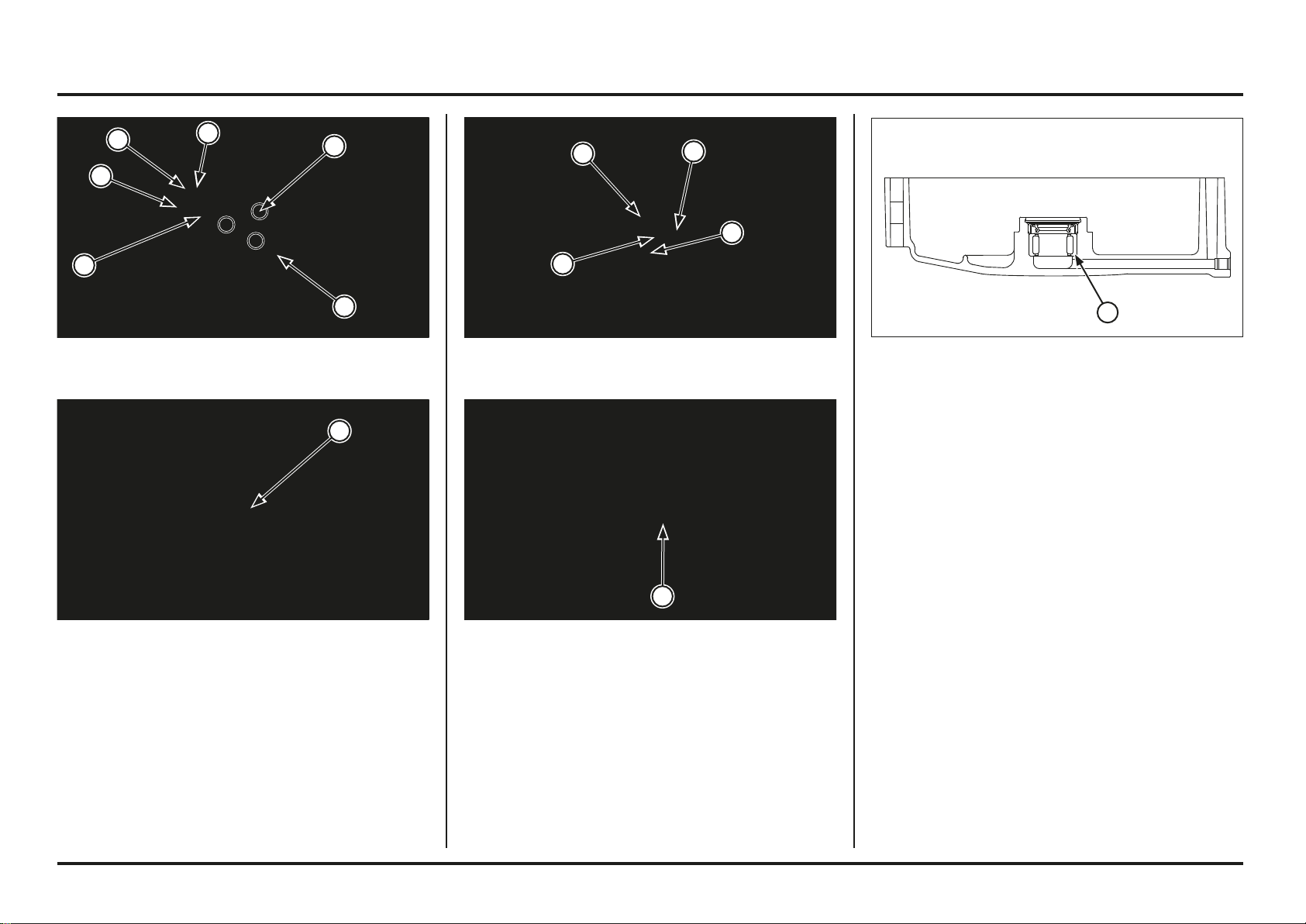
Engine servicing
4-50
4-50
Press new needle bearing into the left crankcase cover
using the special tools.
Tools:
Driver 07749–0010000
Attachment, 22 x 24 mm 07746–0010800
Pilot, 15 mm 07746–0040300
(1) NEEDLE BEARING
(1) BEARING REMOVER
Check the crankshaft oil seal and needle bearing for wear
or damage, replace them if necessary.
Remove the snap ring and washer, then remove the oil
seal.
Remove the needle bearing using the special tools.
Tools:
Bearing remover shaft, 15 mm 07936–KC10100
Bearing remover head, 15 mm 07936–KC10200
Remover weight 07741–0010201
(1) SNAP RING (2) WASHER
(3) OIL SEAL (4) NEEDLE BEARING
(1) OIL PRESSURE RELIEF VALVE
Disassembly/Assembly
Remove the ignition pulse generator mounting flange
bolts and alternator wire clamp.
Remove the stator mounting socket bolts.
Remove the stator/ignition pulse generator from the left
crankcase cover.
Remove the oil pressure relief valve (page 4-1).
(1) BOLTS (2) IGNITION PULSE GENERATOR
(3) WIRE GUIDE (4) SOCKET BOLTS
(5) STATOR
5
4
3
2
1
1
4
3
2
1
1
1
1
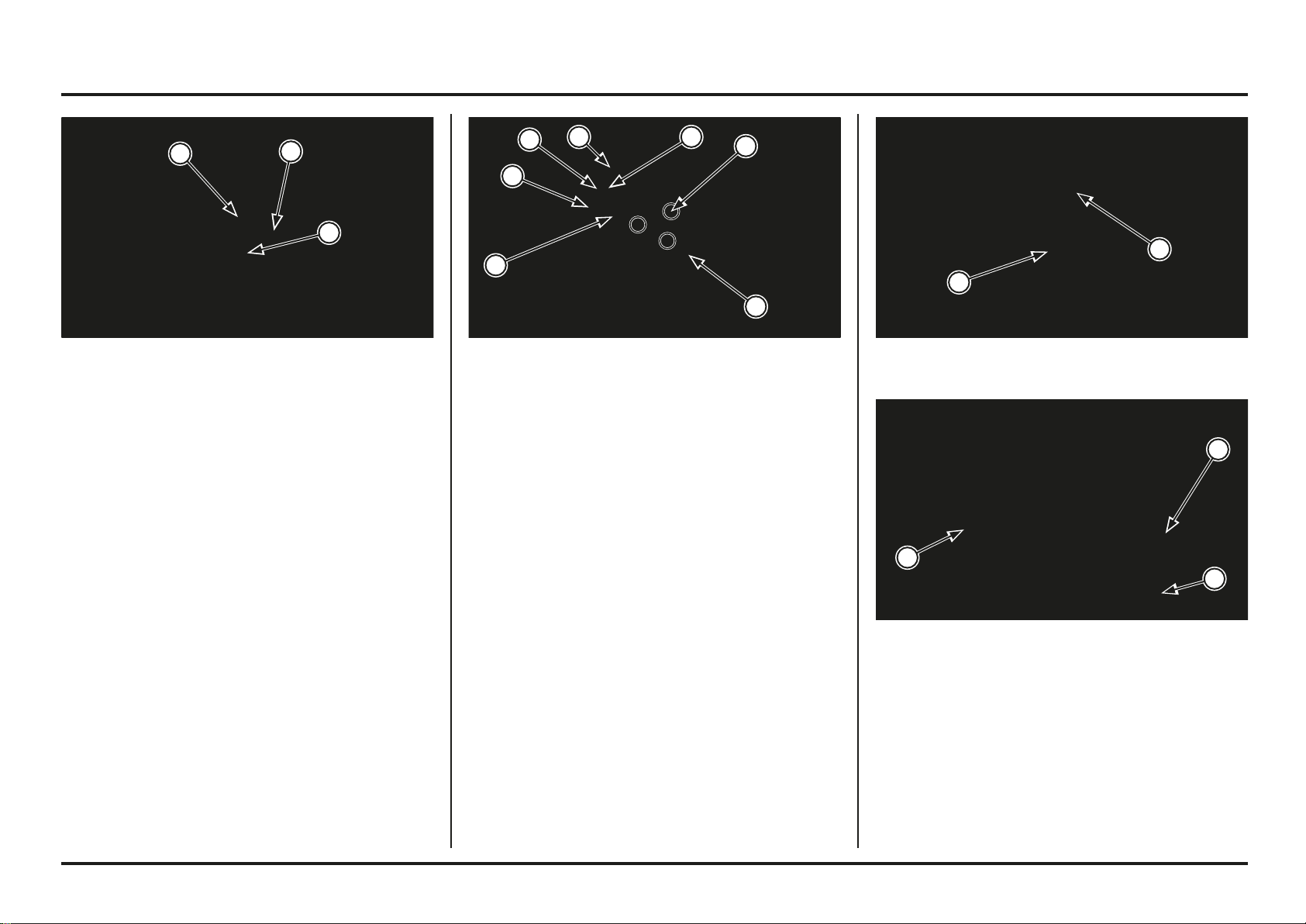
Engine servicing
4-51
4-51
(1) DOWEL PINS
(2) NEW GASKET
Installation
Check the oil filter cover O-ring is in groove condition,
replace if necessary.
Install dowel pins and new gasket.
(1) OIL FILTER COVER
(2) O-RING
(1) STATOR
(2) IGNITION PULSE GENERATOR
(3) WIRE CLAMP
(4) SOCKET BOLTS
(5) BOLTS
(6) GROMMET
Install the stator and ignition pulse generator assembly
into the left crankcase cover.
Apply locking agent to the stator and ignition pulse
generator mounting bolt threads.
Install the alternator wire clamp.
Install the stator and ignition pulse generator mounting
bolts.
Tighten the stator mounting bolts to the specified torque.
Torque: 5.4 N•m (0.55 kgf•m, 4.0 lbf•ft)
Tighten the ignition pulse generator mounting bolts to the
specified torque.
Torque: 5.4 N•m (0.55 kgf•m, 4.0 lbf•ft)
Apply sealant to the stator/ignition pulse generator wire
grommet and install it into the left crankcase cover groove.
(1) OIL SEAL
(2) WASHER
(3) SNAP RING
Apply grease to the new oil seal lip and install it into the
left crankcase cover.
Install the washer and snap ring.
Install the oil pressure relief valve (page 4-1).
1
4
3
2
5
5
1
2
3
6
2
1
2
1
1
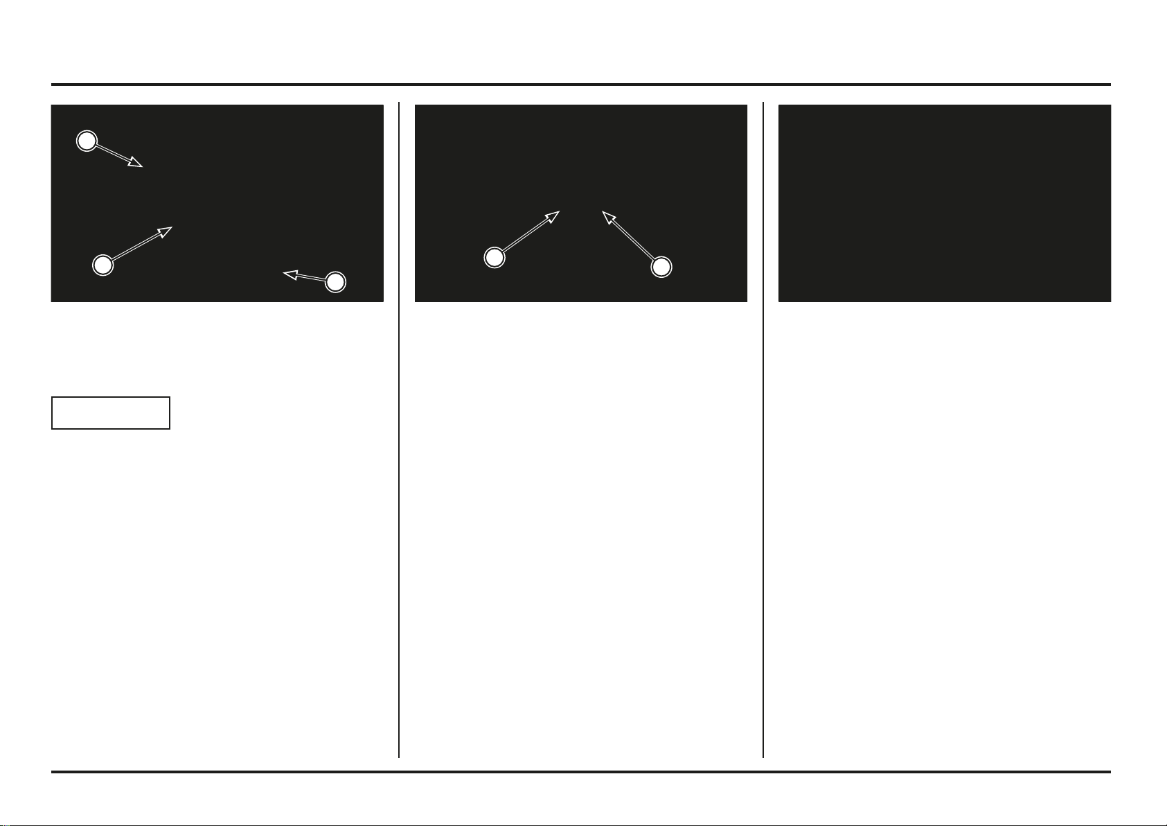
Engine servicing
4-52
4-52
Flywheel
Removal
Remove the left crankcase cover (page 4-49).
Hold the flywheel with flywheel holder, loosen the
flywheel nut.
Tool:
Flywheel holder 89020–NN4–003
Install the gearshift pedal.
Connect the alternator 3P (Natural) connector and ignition
pulse generator 2P (Natural) connectors.
Pour recommended engine oil up to proper level.
Install the slid plate.
(1) 3P (NATURAL) CONNECTOR
(2) 2P (NATURAL) CONNECTOR
Install the left crankcase cover being careful not to
damage the oil filter cover O-ring.
NOTICE
The left crankcase cover (stator) is magnetically attached
to the fl ywheel, be careful during installation.
Install and tighten the bolts in a crisscross pattern in 2 or
3 steps.
Install the new sealing washer and engine oil drain bolt,
tighten the bolt to the specified torque.
Torque: 22 N•m (2.2 kgf•m, 16 lbf•ft)
(1) LEFT CRANKCASE COVER
(2) BOLTS
(3) NEW SEALING WASHER/DRAIN BOLT
1
2
3
2
1
Engine servicing
4-53
4-53
Hold the flywheel with flywheel holder, tighten the
flywheel nut to the specified torque.
Tool:
Flywheel holder 89020–NN4–003
Torque: 167 N•m (17.0 kgf•m, 123 lbf•ft)
Install the left crankcase cover (page 4-50).
Install the flywheel onto the crankshaft.
Apply oil to the flywheel nut threads and seating surface.
Install the washer and flywheel nut.
(1) WASHER
(2) FLYWHEEL NUT
(3) APPLY OIL
(1) WOODRUFF KEY
Remove the flywheel using the special tool.
Tool:
Flywheel puller (Generic tool)
Remove the woodruff key.
Installation
Install the woodruff key onto the crankshaft groove.
(1) FLYWHEEL PULLER
(2) FLYWHEEL
3
2
1
1
2
1
Engine servicing
4-54
4-54
(1) CLUTCH OUTER
(2) GEAR HOLDER
(3) PRIMARY DRIVE GEAR
Temporarily install the clutch outer guide, needle bearing
and clutch outer onto the mainshaft and attach the gear
holder between the primary drive and driven gears.
Remove the primary drive gear bolt.
Tool:
Gear holder 07724-0010100
Remove the washer, primary drive gear and drive gear
collar.
(1) OIL PUMP DRIVEN GEAR
(2) DRIVE PIN
Remove the countershaft collar and O-ring.
Remove the oil pump driven gear and drive pin.
(1) COUNTERSHAFT COLLAR
(2) O-RING
(1) DRIVE SPROCKET
(2) UNIVERSAL HOLDER
(3) BOLT
(4) SPRING WASHER
Crankcase Separation/Disassembly
Remove the engine from the frame.
Remove the following:
– Cylinder head, cylinder, piston
– Clutch
– Kickstarter
– Gearshift linkage
– Flywheel and stator
– Oil filter
– Crankcase breather hose
Hold the drive sprocket with the universal holder and
remove the drive sprocket bolt, spring washer and drive
sprocket.
4
3
2
1
2
1
1
2
3
2
1
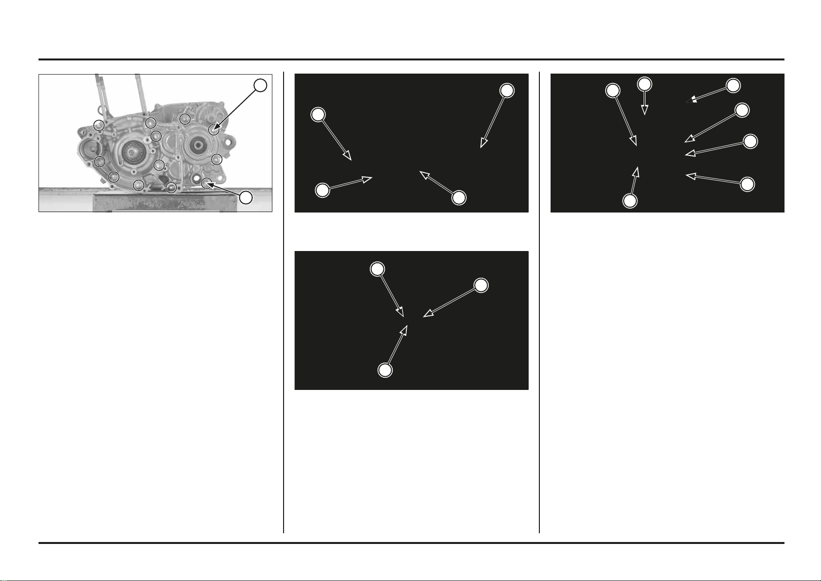
Engine servicing
4-55
4-55
(1) SHIFT FORK SHAFTS
(2) SHIFT FORKS
(3) MAINSHAFT
(4) COUNTERSHAFT
Remove the following:
– Crankshaft
– Shift fork shafts, shift forks and shift drum
– Mainshaft and countershaft assembly
Disassemble the mainshaft and countershaft.
(1) OIL PUMP SHAFT
(2) INNER ROTOR
(3) OUTER ROTOR
Place the right crankcase facing down and remove the left
crankcase from the right crankcase.
Remove the gasket and dowel pins.
Remove the one-way reed valve.
Remove the oil pump shaft, oil pump inner and outer
rotors.
(1) GASKET
(2) DOWEL PINS
(3) ONE-WAY REED VALVE
Remove the transmission oil drain bolt and sealing washer.
Loosen the crankcase bolts in a crisscross pattern in 2 or
3 steps.
Remove the crankcase bolts.
(1) TRANSMISSION OIL DRAIN BOLT
(2) CRANKCASE BOLTS
1
2
3
1
2
3
2
2
1
4
3
2
1
1
2
2
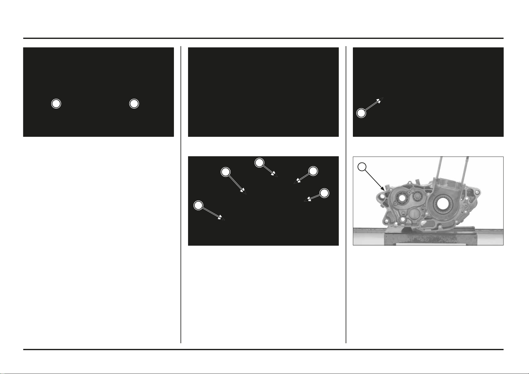
Engine servicing
4-56
4-56
(1) LEFT CRANKCASE
Crankcase Bearing Replacement
Remove the oil seals and bearing set plates.
Drive out the bearing using the special tools (Tools; page
2-7).
Install the new bearing as shown in the illustration using
the special tools.
(1) RIGHT CRANKCASE
(1) RIGHT SHIFT FORK
(2) LEFT SHIFT FORK
(3) RIGHT/LEFT SHIFT FORK SHAFT
(4) CENTER SHIFT FORK/SHAFT
(5) SHIFT DRUM
Inspect each part for wear or damage.
Check the following items (specifications; page 2-1).
Spinning gear I.D.
Bushing I.D. and O.D.
Mainshaft and countershaft O.D.
Shift fork I.D. and claw thickness
Shift fork shaft O.D.
Shift drum O.D.
Crankshaft/Transmission Inspection
Measure the crankshaft runout.
Support the crankshaft at point “A” and “B”, and then
measure the runout at the points “C” and “D”.
Service limit: C: 0.05 mm (0.002 in)
D: 0.03 mm (0.001 in)
Measure the connecting rod big end side clearance and
big end axial/radial play (specification; page 2-3).
8 mm
A
6 mm
B
C D
1
5
4
3
2
1
1
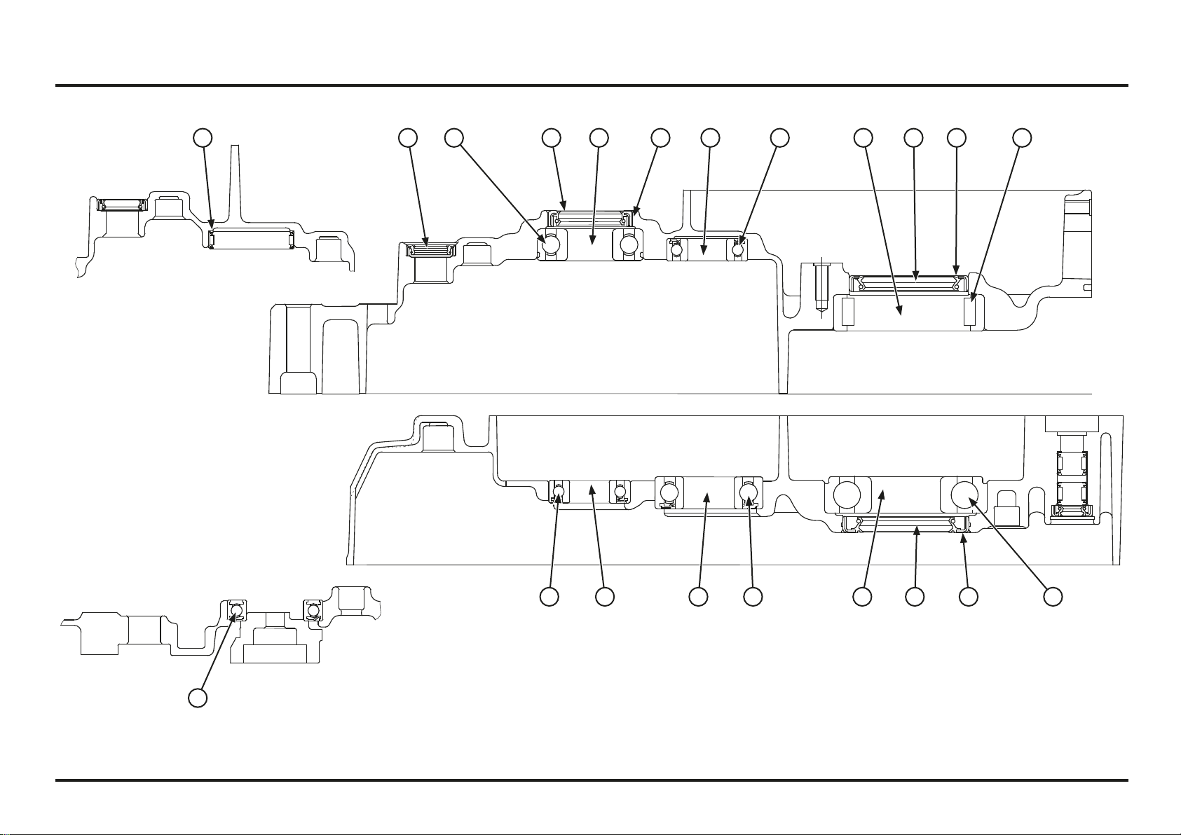
4-57
4-57
Engine servicing
Crankcase Bearings/Oil Seals Location
(1) LEFT SHIFT DRUM BEARING
(2) LEFT COUNTERSHAFT BEARING
(3) LEFT COUNTERSHAFT OIL SEAL
(4) LEFT MAINSHAFT BEARING
(5) LEFT CRANKSHAFT OIL SEAL
(6) LEFT CRANKSHAFT BEARING
(7) RIGHT CRANKSHAFT BEARING
(8) RIGHT CRANKSHAFT OIL SEAL
(9) RIGHT MAINSHAFT BEARING
(10) RIGHT COUNTERSHAFT BEARING
(11) RIGHT SHIFT DRUM BEARING
A: 1 mm
B: 0 ± 0.5 mm
C: 58.60 – 58.88 mm
D: 58.30 – 58.52 mm
E: 1 ± 0.5 mm
F: 27.60 – 27.82 mm
G: 28.50 – 28.72 mm
H: 27.00 – 27.22 mm
I: 27.00 – 27.22 mm
J: 0 ± 0.5 mm
11
10 9 8 7
654321 BC D F
G H I J
EA
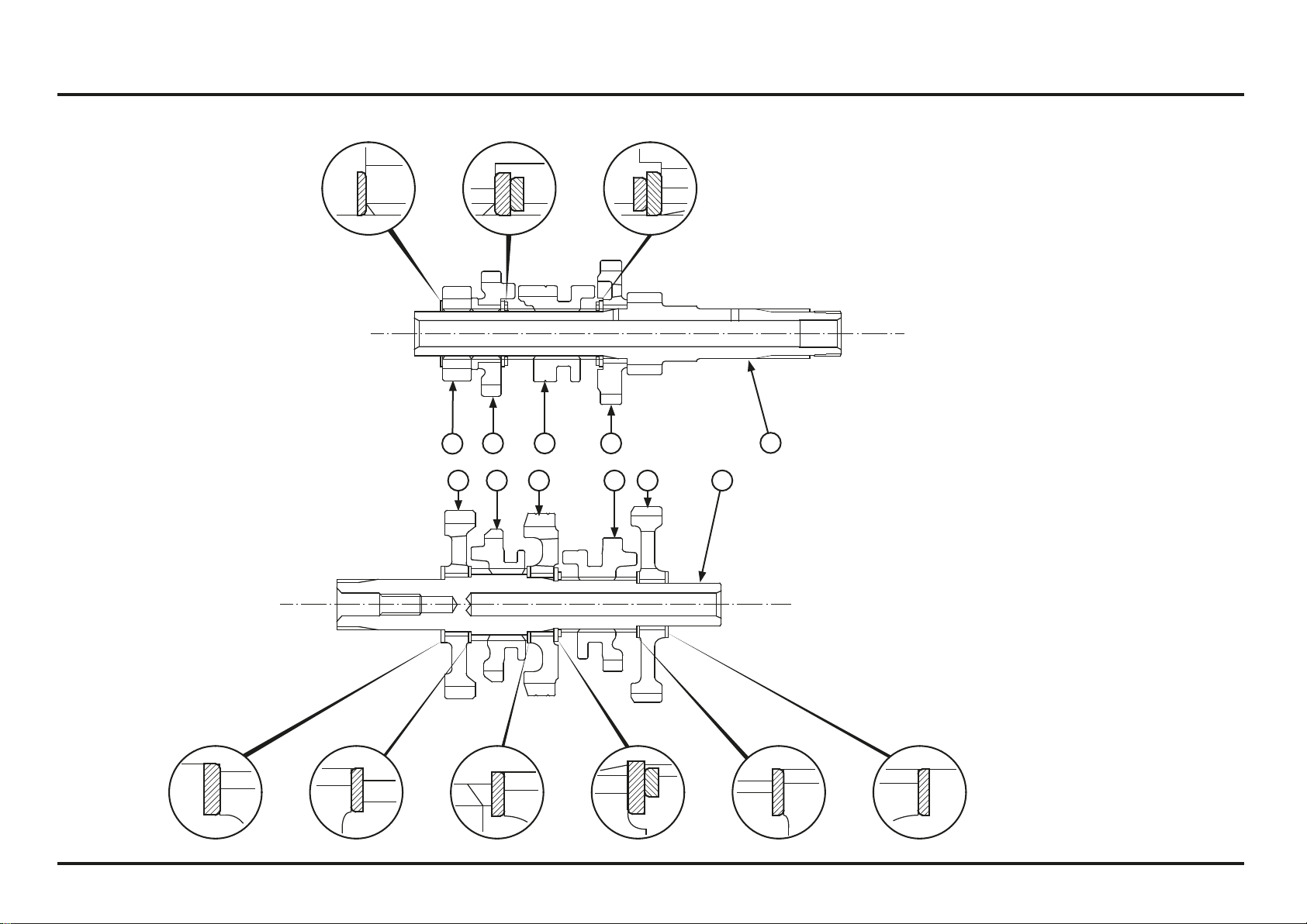
4-58
4-58
Engine servicing
Transmission Assembly
(1) M2 (13T)
(2) M4 (28T)
(3) M3 (15T)
(4) M5 (22T)
(5) MAINSHAFT/M1 (15T)
(6) C2 (31T)
(7) C4 (28T)
(8) C3 (30T)
(9) C5 (22T)
(10) C1 (42T)
(11) COUNTERSHAFT
11109876
432
1
5
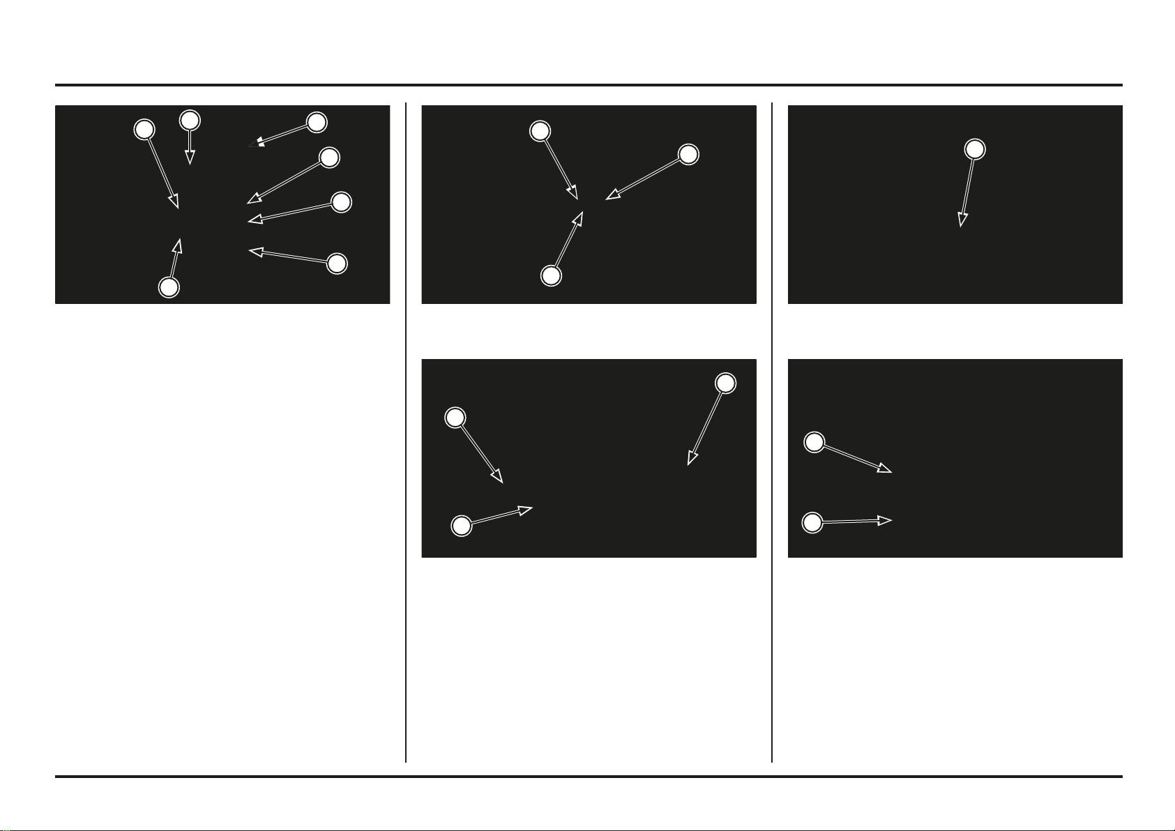
Engine servicing
4-59
4-59
(1) MAINSHAFT
(2) COUNTERSHAFT
(3) SHIFT FORK SHAFTS
(4) LEFT SHIFT FORK
(5) RIGHT SHIFT FORK
(6) CENTER SHIFT FORK
Crankcase Combination
Clean the crankcase mating surfaces before assembling
and check for wear or damage.
If the minor roughness or irregularities on the crankcase
mating surfaces, dress them with an oil stone.
Lubricate the crankshaft bearing with engine oil.
Lubricate the transmission bearings with transmission oil.
Install the crankshaft into the right crankcase.
Install the mainshaft and countershaft as an assembly
into the right crankcase.
Install the center shift fork with its identification mark
facing in.
Install the right and left shift forks with their identification
marks facing out.
Install the shift drum.
Install the shift forks.
(1) OIL PUMP SHAFT
(2) INNER ROTOR
(3) OUTER ROTOR
(1) ONE-WAY REED VALVE
(1) DOWEL PINS
(2) NEW GASKET
Install the oil pump shaft, oil pump inner rotor and outer
rotors.
Install the dowel pins and new gasket.
(1) RIGHT CRANKCASE
(2) LEFT CRANKCASE
Install the one-way reed valve into the right crankcase.
Place the left crankcase onto the right crankcase.
1
2
3
1
1
2
2
1
4
3
3
5
6
1
1
2
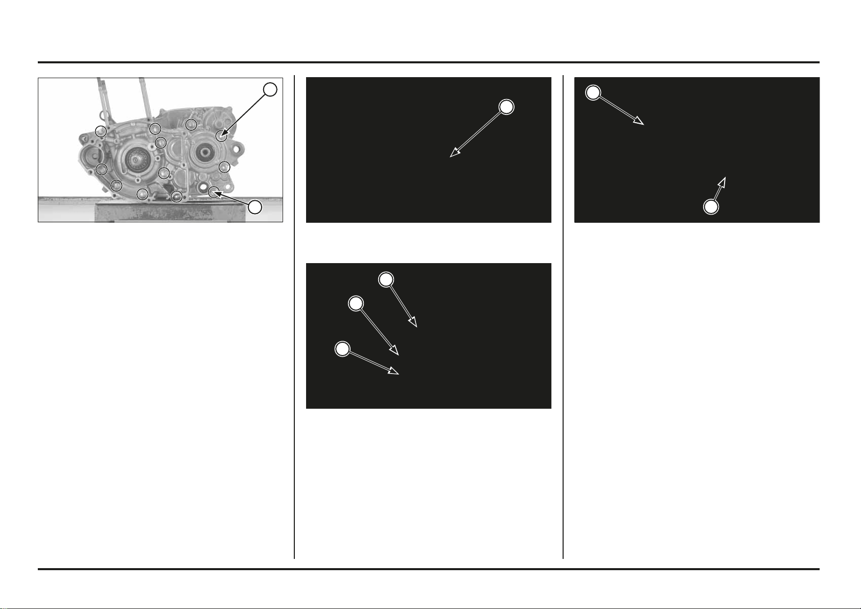
Engine servicing
4-60
4-60
(1) CRANKCASE BOLTS
(2) NEW SEALING WASHER/OIL DRAIN BOLT
(1) DRIVE GEAR COLLAR (1) CLUTCH OUTER
(2) GEAR HOLDER
Install the crankcase bolts.
Tighten the crankcase bolts in a crisscross pattern in 2 – 3
steps.
Install the transmission oil drain bolt with a new sealing
washer, and tighten it to the specified torque.
Torque: 22 N•m (2.2 kgf•m, 16 lbf•ft)
(1) PRIMARY DRIVE GEAR
(2) WASHER
(3) SPECIAL BOLT
Install the primary drive gear collar onto the crankshaft.
Install the primary drive gear with its groove side facing
out.
Apply oil to the primary drive gear special bolt threads and
seating surface.
Install the washer and special bolt.
Temporarily install the clutch outer guide, needle bearing
and clutch outer onto the mainshaft and attach the gear
holder between the primary drive and driven gears.
Tool:
Gear holder 07724-0010100
Tighten the primary drive gear bolt to the specified torque.
Torque: 108 N•m (11.0 kgf•m, 80 lbf•ft)
2
1
1
2
1
3
2
1
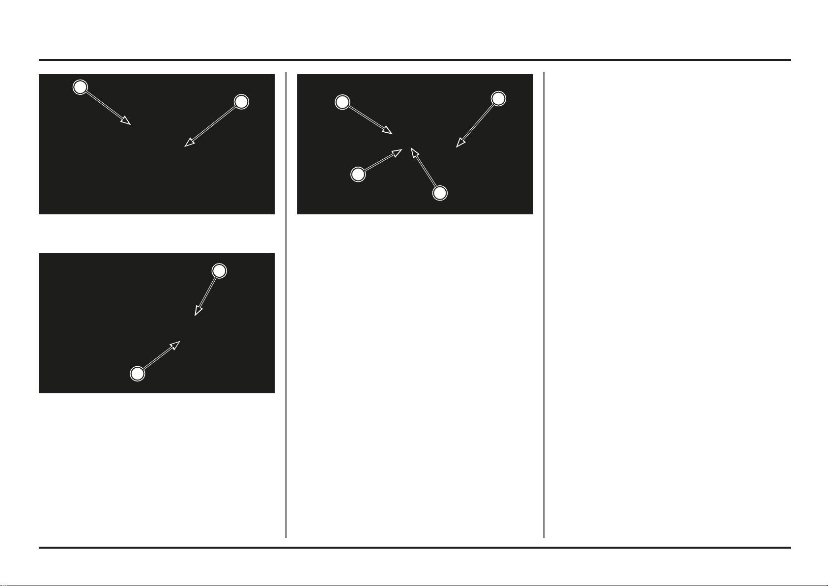
Engine servicing
4-61
4-61
(1) DRIVE PIN
(2) OIL PUMP DRIVEN GEAR
(1) DRIVE SPROCKET
(2) UNIVERSAL HOLDER
(3) SPRING WASHER
(4) BOLT
Install the drive sprocket.
Install the spring washer and drive sprocket bolt.
Hold the drive sprocket with universal holder, tighten the
special bolt to the specified torque.
Torque: 31 N•m (3.2 kgf•m, 23 lbf•ft)
Install the removed parts in the reverse order of removal.
(1) NEW O-RING
(2) COUNTERSHAFT COLLAR
Install the drive pin into the oil pump drive shaft hole.
Install the oil pump driven gear while aligning its groove
with the drive pin.
Apply grease to the new O-ring and install it into the
countershaft collar groove.
Install the countershaft collar.
3
4
2
1
1
2
2
1

4-62
4-62
Memo
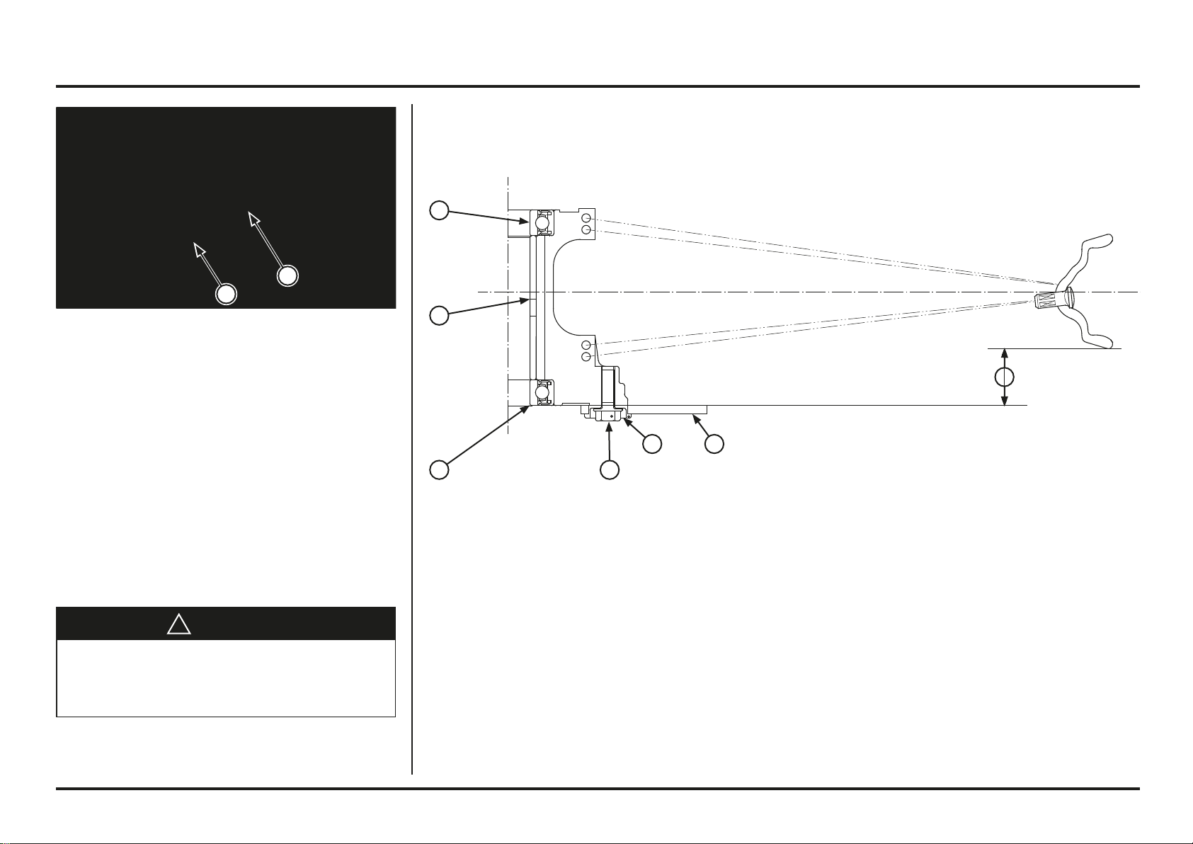
5-1
5-1
(1) AXLE PINCH BOLT
(2) AXLE
Front Wheel
Removal
Remove the brake caliper mounting bolts, disc cover and
collars.
Loosen the axle pinch bolt.
Support the motorcycle and front wheel off the ground.
Remove the axle and front wheel.
Do not depress the brake lever after the front wheel is
removed.
The caliper pistons will move and make reassembly
difficult.
Disassembly/Assembly
!
WARNING
A contaminated brake disc or pad reduces stopping
power, and can cause a serious injury or death.
Discard contaminated pads and clean a contaminated
disc with a high quality brake degreasing agent.
(1) BRAKE DISC
(2) COLLAR
(3) DISC BOLT
(4) LEFT WHEEL BEARING
(5) DISTANCE COLLAR
(6) RIGHT WHEEL BEARING
(a) 27,25 ± 1 mm (1,07 ± 0,0394 in)
5. Frame servicing
Spokes: Check spoke tension frequently between the first
few rides. As the spokes, spoke nuts and rim contact
points seat-in, the spokes may need to be retightened.
Once past this initial seating-in period, the spokes should
hold their tension. Still, be sure your race maintenance
program includes checking spoke tension and overall
wheel condition on a regular basis.
Drive the bearing
into the hub until it
stops.
When unassembling change bolt for new one’s
Apply a locking agent to the threads
Torque: 18 N•m (1.8 kgf•m)
6
5
4 3
2 1
a
2
1
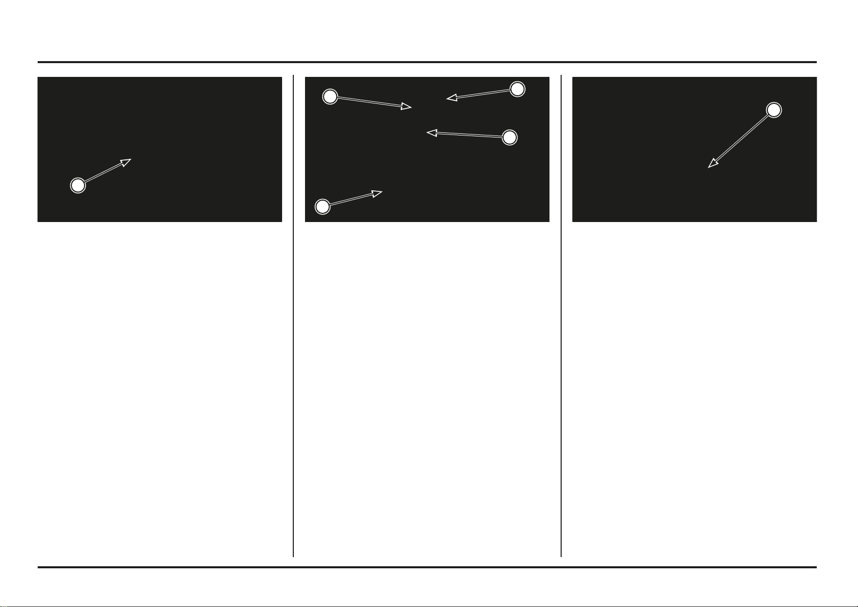
5-2
5-2
Frame servicing
(1) AXLE (1) BRAKE CALIPER
(2) DISC COVER
(3) BOLTS
(1) AXLE PINCH BOLT
Installation
Clean the surfaces where the axle and axle clamps
contact each other.
Place the front wheel between the fork legs.
Apply thin layer of grease to the axle surface.
Apply grease to the axle threads.
Install the axle from the right side through the wheel.
Tighten the axle to the specified torque.
Torque: 69 N•m (7.0 kgf•m, 51 lbf•ft)
Install the brake caliper, flange collars and disc cover.
Apply a locking agent to the threads and tighten the mou-
nting bolts to the specified torque.
Torque: 26 N•m (2.7 kgf•m, 20 lbf•ft)
With the front brake applied, pump the fork up and down
several times to seat the axle and check the front brake
operation.
While keeping the fork parallel, tighten the axle pinch bolt
to the specified torque.
Torque: 21 N•m (2.1 kgf•m, 17 lbf•ft)
1
3
3
2
1
1
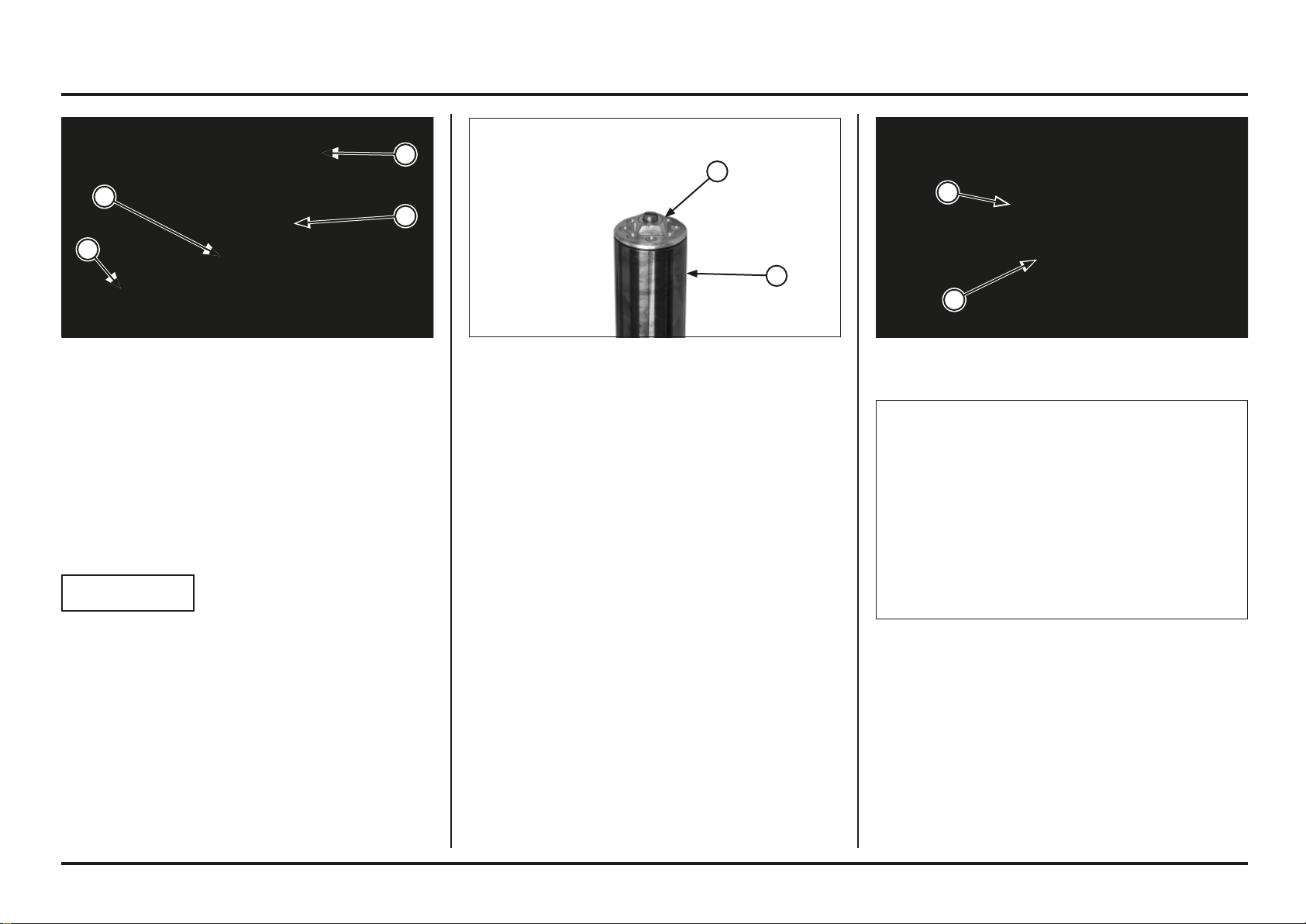
5-3
5-3
Frame servicing
(1) FRONT FENDER
(2) TOP BRIDGE
(3) BOTTOM BRIDGE
(4) FORK LEG
Fork
Removal
Remove the front wheel (page 5-1).
Remove the front fender.
Loosen the top bridge pinch bolt.
If the forks are to be disassembled, loosen the fork bolt.
NOTICE
To avoid damaging the fork bolt threads, loosen the top
bridge pinch bolt before loosening the fork bolts.
Loosen the bottom bridge pinch bolts, and pull the fork
tube down and out.
(1) FORK BOLT
(2) FORK LEG
(1) LOCK NUT
(2) FORK BOLT
Right Fork Disassembly
Before disassembling the fork, clean the entire sliding sur-
face and the bottom of the fork slider.
Be careful not to scratch the fork tube.
A scratched fork tube will damage the seal, causing an
oil leak.
Hold the fork tube, remove the fork bolt and slide the fork
tube down.
Make sure the damping adjuster is in clicked position and
is not in between the position.
Hold the lock nut and remove the fork bolt from the dam-
per rod.
Do not remove the lock nut from the damper rod.
Pour out the fork fluid.
1
2
1
2
4
3
2
1
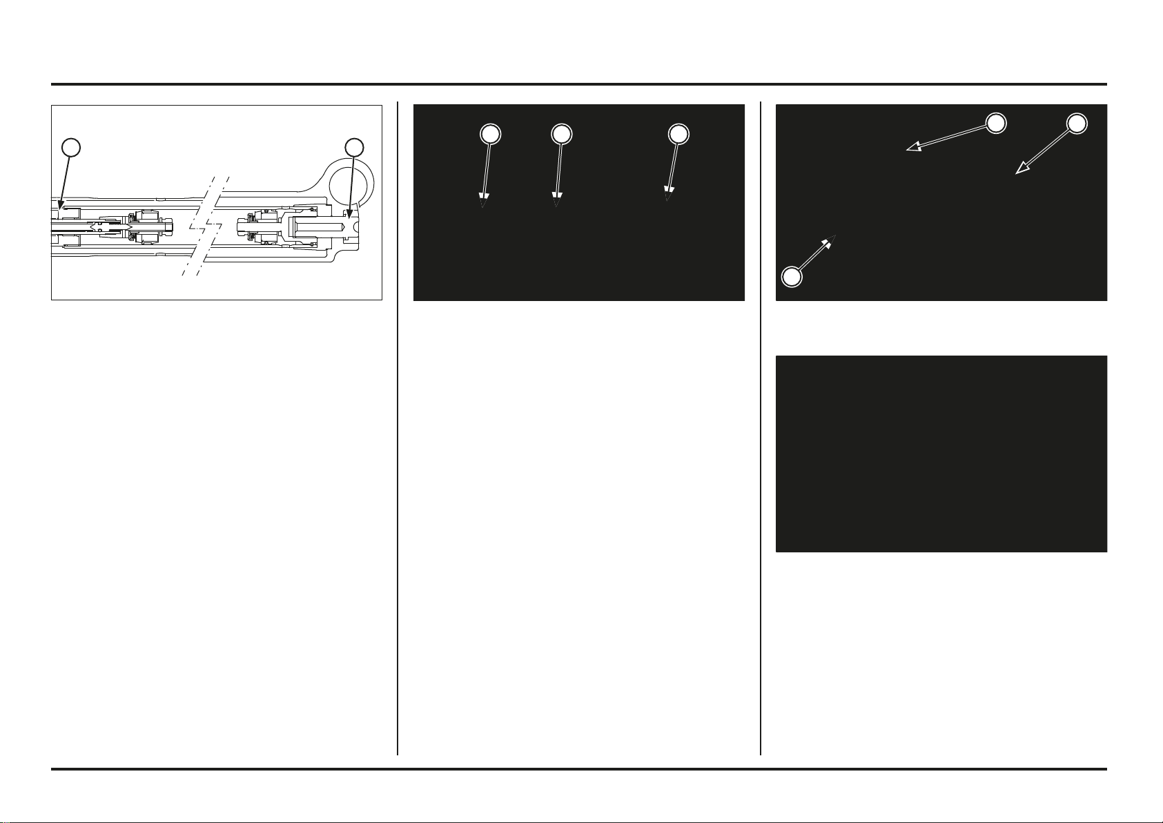
5-4
5-4
Frame servicing
(1) DUST SEAL
(2) STOP RING
(3) FORK SLIDER
Remove the fork damper assembly and centering plate
from the fork tube.
(1) FORK DAMPER
(2) CENTERING PLATE
(3) FORK TUBE
Hold the axle holder in a vise protected with a piece of
woods or soft jaws to avoid damage.
Do not overtighten.
Loosen the right fork center bolt.
Remove the center bolt and sealing washer.
(1) FORK DAMPER
(2) RIGHT FORK CENTER BOLT
Remove the dust seal and stop ring being careful not to
scratch the fork tube.
In quick successive motions, pull the fork tube out of the
slider.
Empty the fork fluid from the damper by pumping the
damper rod 8 - 10 times.
21
3 2 1
2
1
3
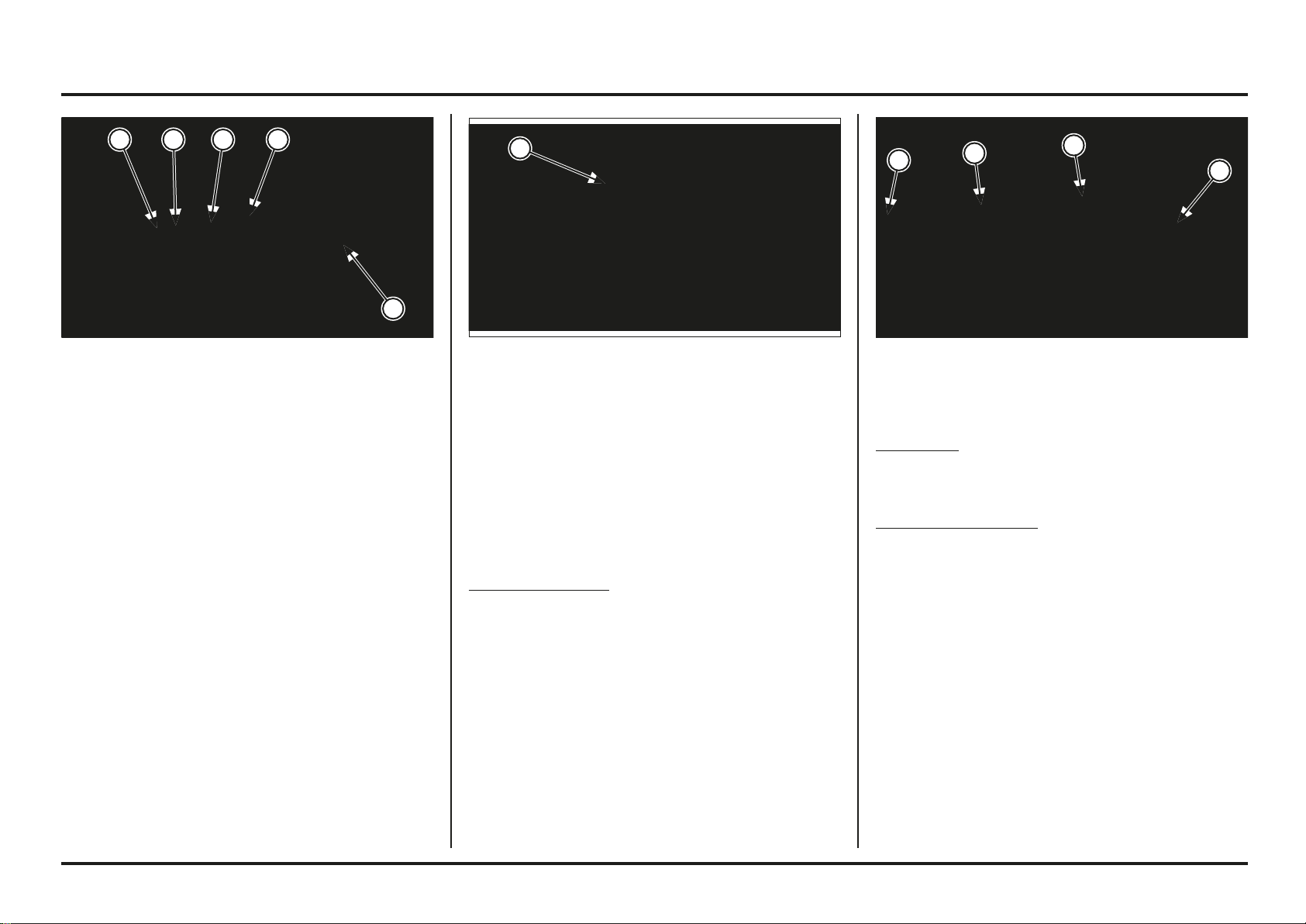
5-5
5-5
Frame servicing
(1) FORK DAMPER
(2) DAMPER ROD
(3) FORK TUBE
(4) CENTERING PLATE
Fork Damper
Check the fork damper assembly for damage or
deformation.
Check the damper rod for bend or other damage.
Fork tube/centering plate
Check the fork tube for bent or deformation.
Check the centering plate for damage.
(1) BUSHING
Right Fork Inspection
Check the following items (specifications; page 2-4):
– Fork tube for score marks, scratches and excessive
wear
– Fork tube runout
– Fork slider for damage or deformation
– Fork damper for damage
Bushing/Back-up Ring
Check the bushings for excessive wear or scratches.
Remove any metal powder inside the slider and guide
bushings with a nylon brush and fork fluid.
If copper appears on the entire surface, replace the
bushing.
Replace the back-up ring if there is any distortion.
(1) FORK TUBE BUSHING
(2) GUIDE BUSHING
(3) BACK-UP RING
(4) OIL SEAL
(5) FORK SLIDER
Check that the fork tube moves smoothly in the slider.
If it does not, check the fork tube bending or damage, and
the bushings for wear or damage. If the slider and bushing
are normal, check the fork tube.
Carefully remove the fork tube bushing by prying the slot
with a screwdriver until the bushing can be pulled off by
hand.
Be careful not to scratch the teflon coating of the bushing.
Remove the guide bushing, back-up ring and oil seal from
the fork tube.
4 3 2 1
4
3
2
1
5
1
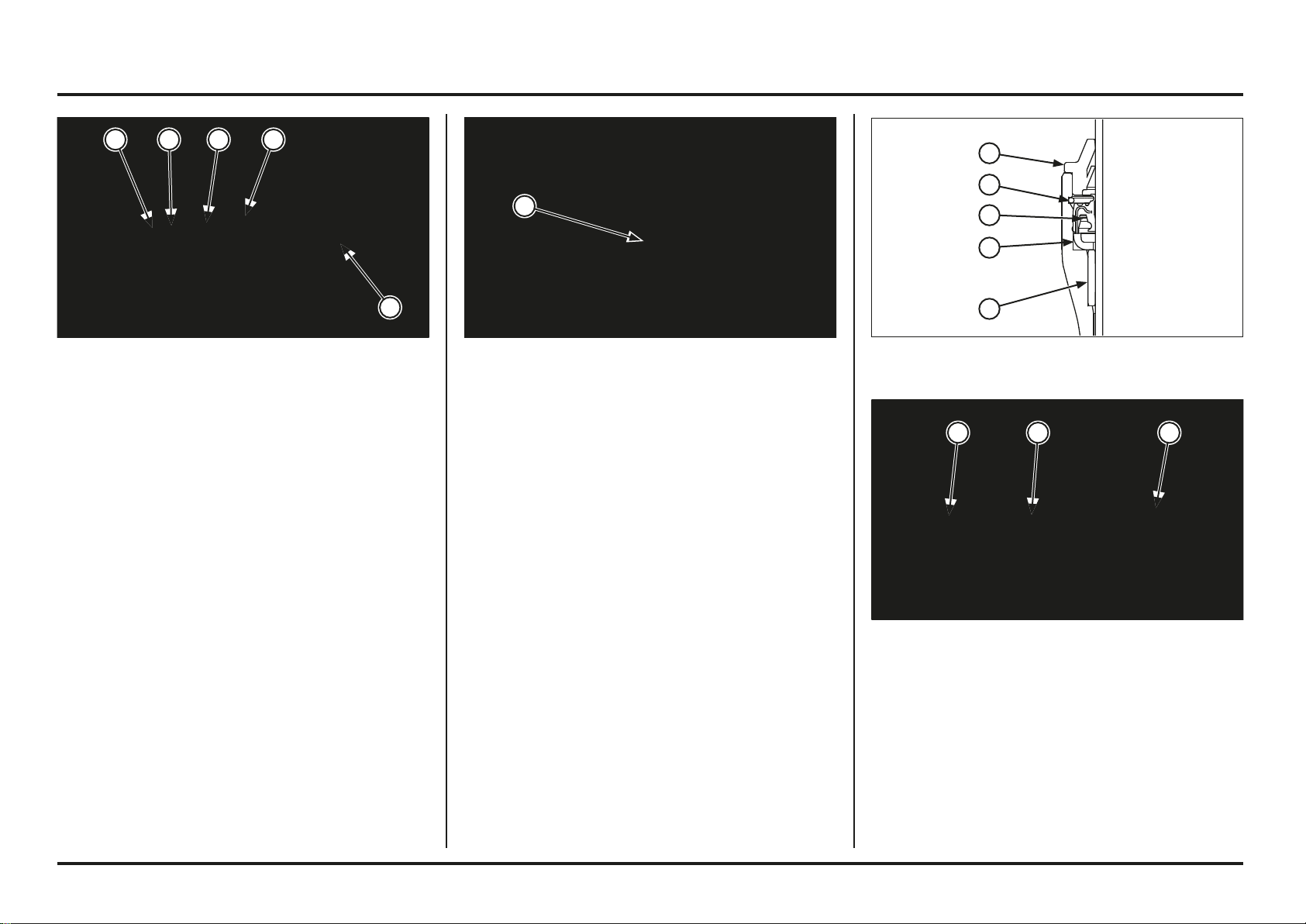
5-6
5-6
Frame servicing
Install the stop ring into the slider groove securely.
Install the dust seal.
Install the centering plate and fork damper into the fork
tube.
(1) FORK DAMPER
(2) CENTERING PLATE
(3) FORK TUBE
(1) FORK SEAL DRIVER(1) FORK TUBE BUSHING
(2) GUIDE BUSHING
(3) BACK-UP RING
(4) OIL SEAL
(5) FORK SLIDER
Right Fork Assembly
Clean the parts thoroughly with non-flammable or high
flush point solvent before assembly.
Install the following to the fork tube:
– Fork tube bushing
– Guide bushing
– Back-up ring
Coat the guide and fork tube bushings with recommended
fork fluid.
Install the fork tube assembly into the slider.
Using the special tool, drive the guide bushing and back-
up ring until the stop ring groove is fully stuck in the fork
slider base.
Install the oil seal (spring up) in the fork slider. Drive the
oil seal using the special tool, performing a constant pres-
sure until stops in back-up ring.
Tool:
Fork seal driver 07947–4630100
(1) GUIDE BUSHING (4) STOP RING
(2) BUCK-UP RING (5) DUST SEAL
(3) OIL SEAL
3 2 1
4 3 2 1
1
5
5
4
3
2
1
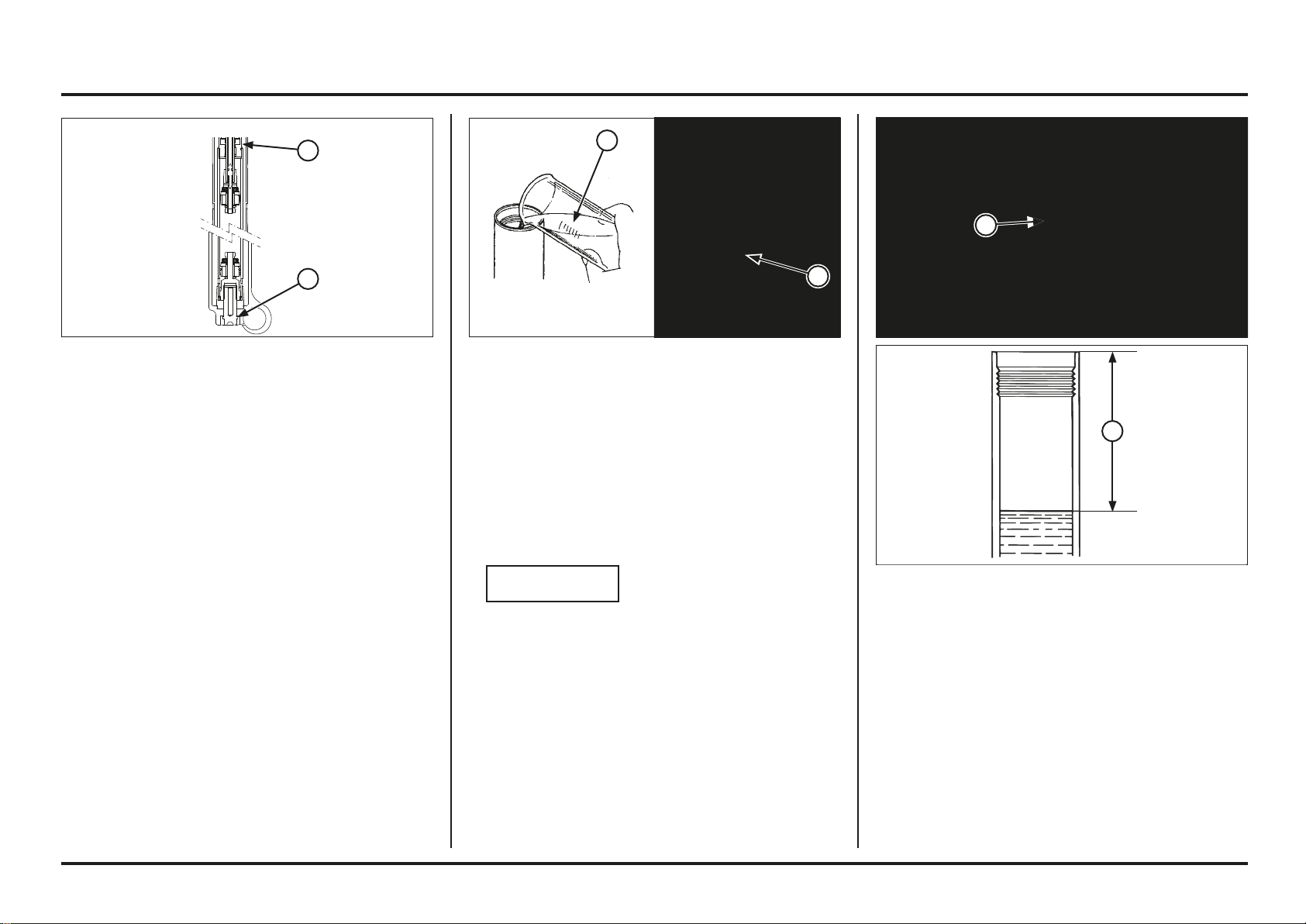
5-7
5-7
Frame servicing
(1) FORK DAMPER ROD
(2) OIL LEVEL
2. Pump the damper rod 8 - 10 times.
3. Make sure no air in fork damper by slowly pull the
damper rod up. If the resistance is felt at the top end,
pump the damper rod again.
Wait 2 – 3 minutes before measuring the oil level.
Measure the oil level from top of the fork tube, with the
fork fully compresed.
Standard oil level: 70 mm (2.8 in)
Oil capacity (orientative): 260 cm
3
(9.2 US oz)
(8.8 Imp oz)
Pour recommended fork fluid in the fork leg.
Specified fork fluid:
OJ Racing Special Fork Oil Type 01 (SAE 5W) or
equivalent
Bleed the air as follows:
1. Extend the fork without bringing to its maximum exten-
sion. Cover the top of the fork tube with your hand and
compress the fork slowly several times.
NOTICE
Totally extended fork may cause oil leakage.
(1) FORK FLUID
(2) FORK TUBE
Hold the axle holder in a vise protected with a piece of
woods or soft jaws to avoid damage.
Do not overtighten the vise.
Install the right fork center bolt with a new sealing washer.
Tighten the right fork center bolt to the specified torque.
Torque: 23.5-25.5 N•m (2.4-2.6 kgf•m)
(1) FORK DAMPER
(2) RIGHT FORK CENTER BOLT
2
1
2
2
1
1
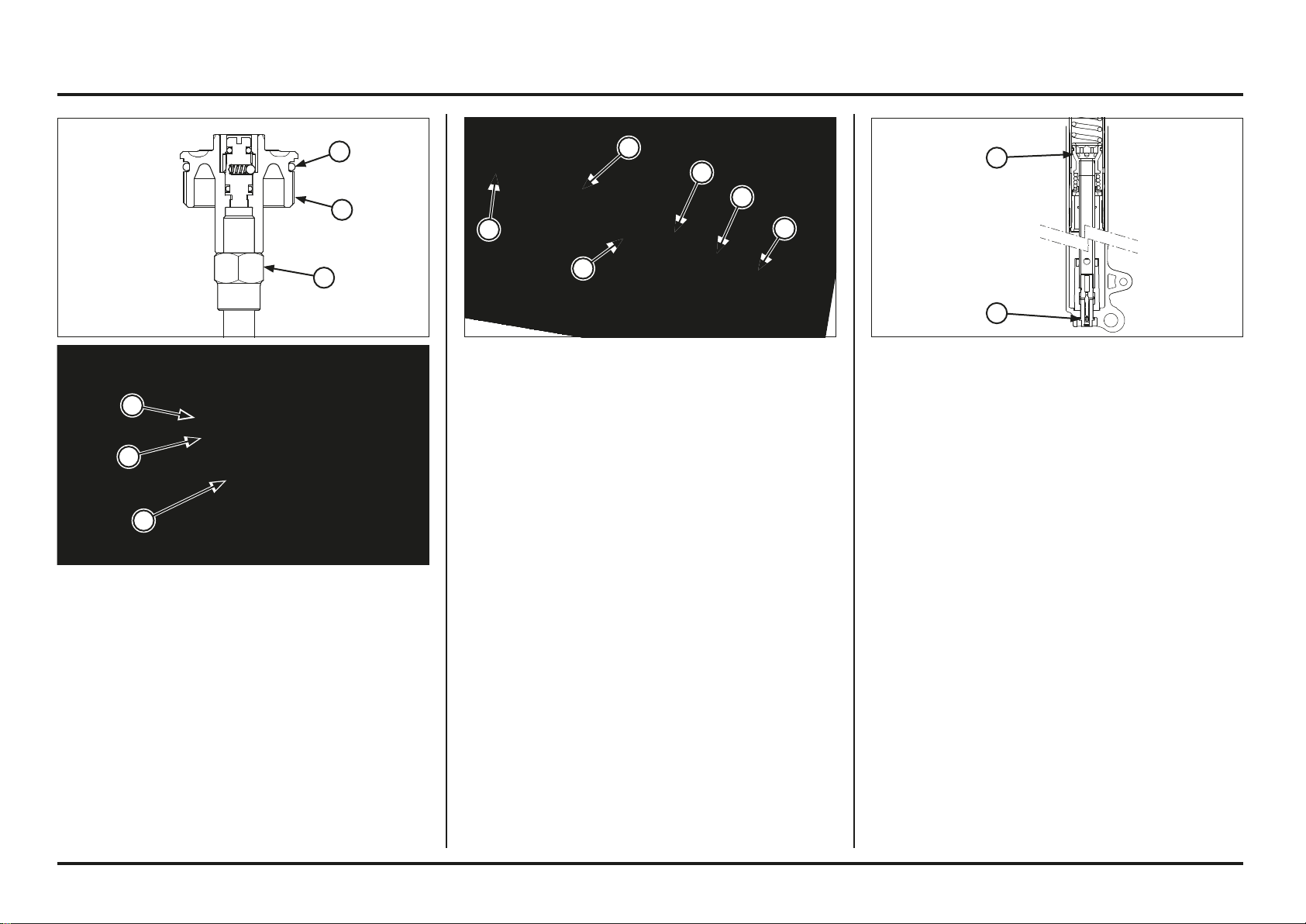
5-8
5-8
Frame servicing
Hold the axle holder in a vise protected with a piece of
wood or soft jaws to avoid damage.
Do not overtighten.
Loosen the left fork center bolt.
Remove the center bolt and sealing washer.
Remove the following items using the same procedure as
the right fork disassembly (page 5-3):
– Dust seal
– Stop ring
– Fork tube, unlocking guide bushing on the fork leg.
(1) CILINDER ASSY
(2) CENTER BOLT
(1) FORK BOLT
(2) DISTANCE COLLAR
(3) SPRING SEAT
(4) FORK SPRING
(5) TAPERED BUSHING
(6) FORK TUBE
Left Fork Disassembly
Before disassembling the fork, clean the entire sliding
surface and the bottom of the fork slider.
Be careful not to scratch the fork tube.
A scratched fork tube will damage the seal, causing an
oil leak.
The fork bolt under spring pressure.
Before removing the fork bolt, turn the pre-load adjuster
softest position.
Remove the fork bolt from the fork tube.
Remove the tapared bushing, distance collar, spring seat
and fork spring.
Pour out the fork fluid.
Install a new O-ring onto the fork bolt groove.
Screw the fork bolt on the lock nut from the damper rod
until it seats.
Hold the lock nut and tighten the fork bolt to the specified
torque.
Torque: 15 N•m (1.5 kgf•m)
Apply recommended fork fluid to the O-ring, then screw
the fork bolt into the fork tube.
Torque: 13 N•m (1.3 kgf•m)
(1) LOCK NUT
(2) NEW O-RING
(3) FORK BOLT
3
2
1
4
3
2
1
5
2
3
1
2
1
6
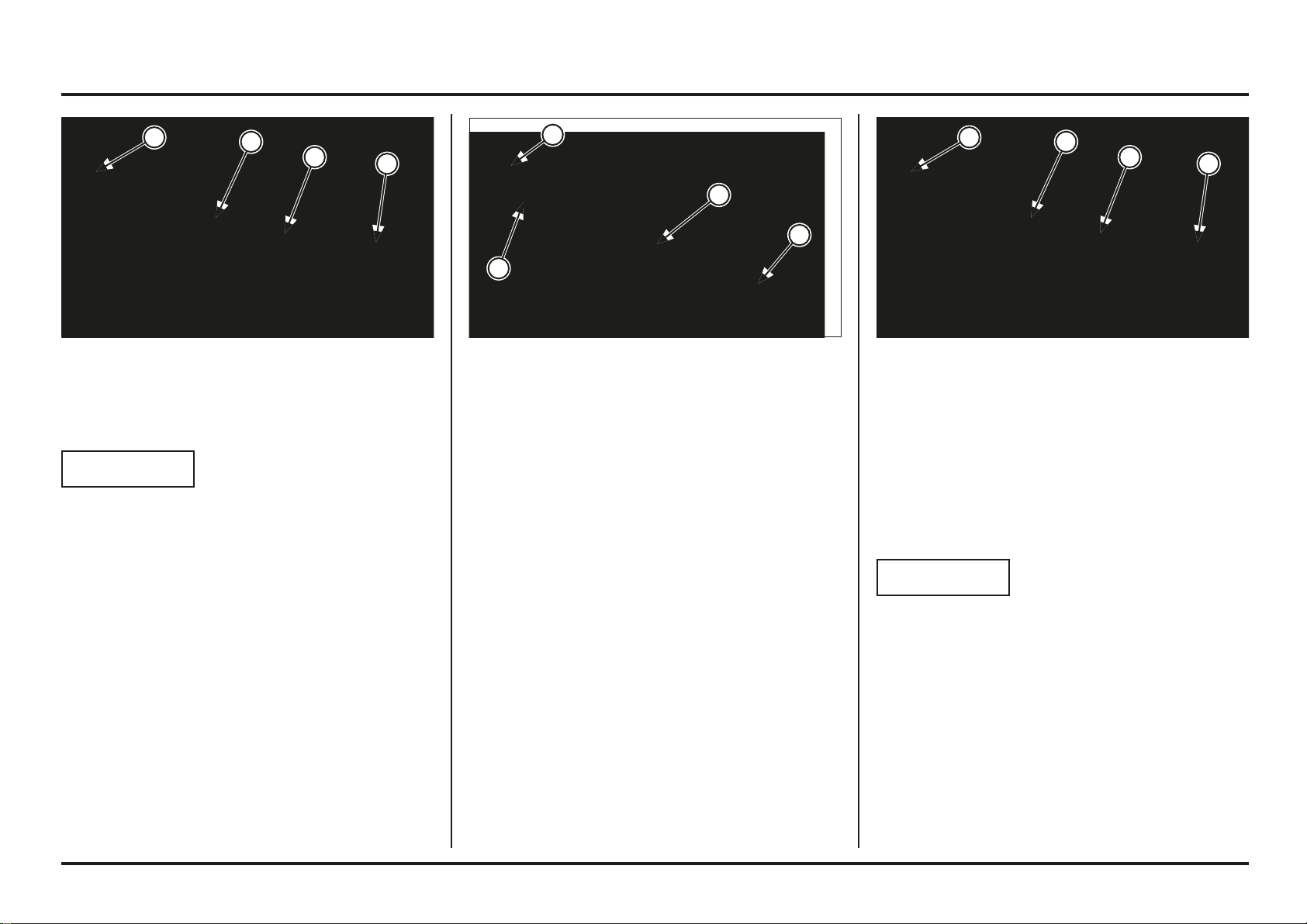
5-9
5-9
Frame servicing
(1) CILINDER ASSY
(2) PISTON RING
(3) REBOUND SPRING
(4) TAPERED BUSHING
Left Fork Inspection
Check the following items (page 2-4):
– Inside fork slider for damage or deformation
– Fork tube runout
– Fork spring free length
– Fork tube for score marks, scratches and excessive
wear
– Bushing/back-up ring (page 5-5)
– Fork piston ring for wear or damage
– Tapared bushing for damage
– Rebound spring for fatigue or other damage
(1) FORK TUBE
(2) CILINDER ASSY
(3) TAPERED BUSHING
(4) FORK SLIDER
Remove the tapared bushing from the cilinder assy.
NOTICE
Be careful not to damage the tapared bushing.
Remove the cilinder assy from the fork tube.
Remove the following items using the same procedure as
the right fork disassembly (page 5-3):
– Oil seal
– Back-up ring
– Guide bushing
– Fork tube bushing
(1) FORK TUBE
(2) CILINDER ASSY
(3) TAPERED BUSHING
(4) FORK SLIDER
Left Fork Assembly
Clean the parts thoroughly with non-flammable or high
flush point solvent before assembly.
Apply fork fluid to the piston ring.
Install the cilinder assy into the fork tube.
Install the tapered bushing on the end of the cilinder assy.
NOTICE
The tapered bushing is easy to scratched or deformed.
Take care not to damage it when assembling it.
3
2
1
4
3
2
1
3
2
1
4 4
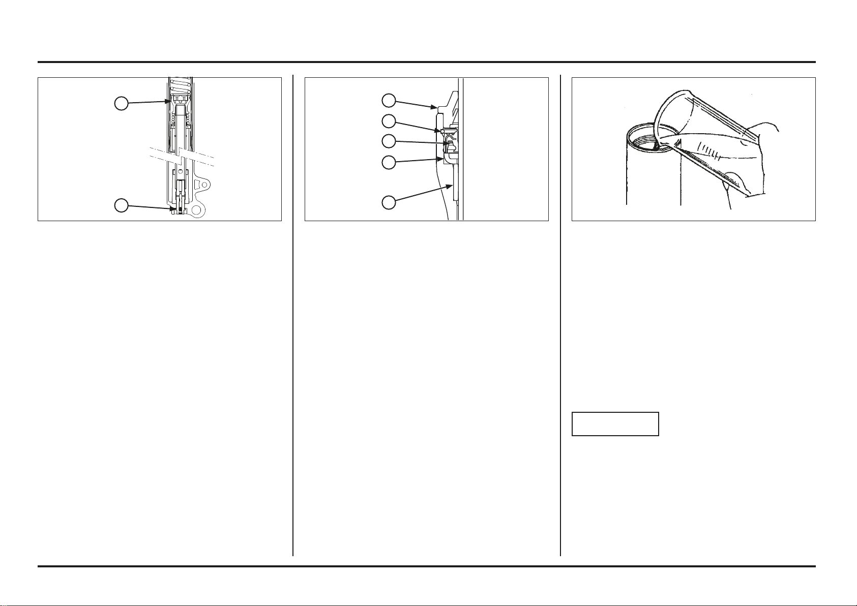
5-10
5-10
Frame servicing
Pour half the required amount of recommended fork fluid
in the fork tube.
Specified fork fluid:
OJ Racing Special Fork Oil Type 01 (SAE 5W) or
equivalent
Pump the fork tube slowly 8-10 times.
Pour additional fluid to the specified capacity.
Oil level: 125 mm (4.9 in)
Oil capacity (orientative): 285 cc
(9.6 US oz)
(10.0 Imp oz)
NOTICE
Totally extended fork may cause oil leakage.
(1) GUIDE BUSHING
(2) BACK-UP RING
(3) OIL SEAL
(4) STOP RING
(5) DUST SEAL
Install the following parts onto the fork tube using the
same procedure as the right fork (page 5-6):
– Fork tube bushing
– Guide bushing
– Back-up ring
Using the special tool, drive the guide bushing and back-
up ring until the stop ring groove is fully stuck in the fork
slider base.
Install the oil seal (spring up) in the fork slider. Drive the
oil seal using the special tool, performing a constant pres-
sure until stops in back-up ring.
Tool:
Fork seal driver 07947–4630100
Install the stop ring into the slider groove securely.
Install the dust seal.
Hold the axle holder in a vise protected with a piece of
wood or soft jaws to avoid damage.
Do not overtighten the vise.
Install the center bolt with a new sealing washer.
Tighten the center bolt to the specified torque.
Torque: 23.5-25.5 N•m (2.4-2.6 kgf•m)
(1) CILINDER ASSY
(2) CENTER BOLT
2
1
5
4
3
2
1
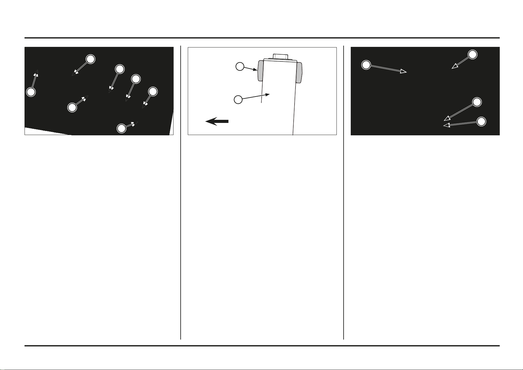
5-11
5-11
Frame servicing
Installation
Install the fork tube.
Raise the fork through the bottom bridge and top bridge.
Place the fork tubes in the top clamp level as shown in
the picture.
(1) FORK TUBE
(2) TOP BRIDGE
(1) FORK SPRING
(2) SPRING SEAT
(3) DISTANCE COLLAR
(4) O-RING (NEW)
(5) FORK BOLT
(6) TAPERED BUSHING
(7) FORK TUBE
Install the fork spring, spring seat, distance collar and the
tapered bushing.
Apply recommended fork fluid to the new O-ring, then
screw the fork bolt into the fork tube.
Torque: 13 N•m (1.3 kgf•m. 9.3 lbf•ft)
Tighten the bottom bridge pinch bolts to the specified
torque.
Torque: 21 N•m (2.1 kgf•m, 14 lbf•ft)
Overtightening the pinch bolts can deform the outer tube.
Deformed outer tube must be replaced.
Tighten the fork bolt.
Tighten the top bridge pinch bolt to the specified torque.
Torque: 21 N•m (2.1 kgf•m, 14 lbf•ft)
Return spring pre-load and rebound adjuster to their
original positions as noted during removal.
Install the following:
– Front fender
– Front wheel (page 5-2)
(1) BOTTOM BRIDGE PINCH BOLTS
(2) FORK BOLT
(3) TOP BRIDGE PINCH BOLTS
FORWARD
4
2
1
1
2
3
5
6
3
2
1
1
7
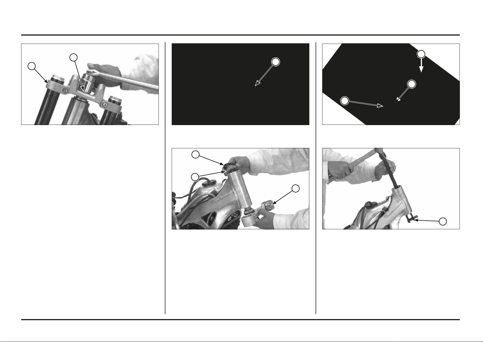
5-12
5-12
Frame servicing
(1) BALL RACE REMOVER
Remove the lower bearing and dust seal from the steering
stem.
Remove the upper and lower bearing races from the
steering head using the special tools.
Tool:
Ball race remover 07948-4630100
(1) STEM
(2) LOWER BEARING
(3) DUST SEAL
(1) DUST SEAL
(2) UPPER BEARING
(3) STEERING STEM
Remove the stem bearing adjusting nut.
Remove the following;
– Dust seal
– Upper bearing
– Steering stem/lower bearing
(1) ADJUSTING NUT
Steering stem
Disassembly
Remove the following:
– Handlebar
– Front wheel (page 5-1)
– Front fender
Remove the steering stem nut and washer.
Remove the fork legs (page 5-3).
Remove the top bridge.
(1) STEM NUT
(2) TOP BRIDGE
2
1
1
3
2
1
3
2
1
1
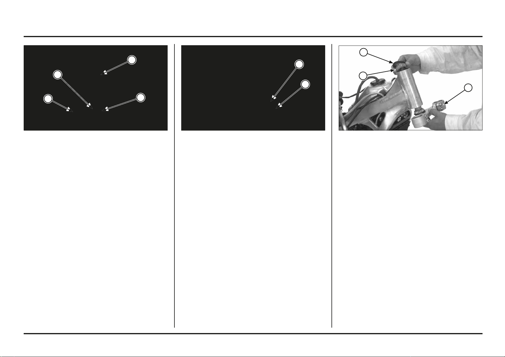
5-13
5-13
Frame servicing
Tools:
Driver 07749-0010000
Attachment, 42 x 47 mm 07746-0010300
(1) DRIVER
(2) ATTACHMENT
(1) STEM
(2) DUST SEAL
(3) BEARING
(4) STEERING STEM DRIVER
Install new dust seal onto the steering stem.
Install the new lower bearing into the steering stem using
a hydraulic press and driver.
Tool:
Steering stem driver (Generic tool)
(1) STEM
(2) UPPER BEARING
(3) DUST SEAL
Install new bearing races.
Pack the upper and lower bearings with grease.
Install the steering stem, upper bearing and dust seal.
3
2
2
1
1
4
1
2
3

5-14
5-14
Frame servicing
Apply grease to the stem nut thread and seating surfaces.
Install the top bridge, washer and stem nut.
Temporarily install both fork legs.
Apply grease to the top bridge pinch bolt threads and
seating surfaces.
Install and tighten the top bridge pinch bolts to the
specified torque.
Torque: 21 N•m (2.1 kgf•m, 15.4 lbf•ft)
Tighten the stem nut to the specified torque.
Torque: 99 N•m (10 kgf•m, 65 lbf•ft)
Recheck the steering stem adjustment before installing
the removed parts.
(1) TOP BRIDGE
(2) STEM NUT
Turn the steering stem lock-to-lock 5 times to seat the
bearings and retighten the adjusting nut to the specified
torque.
Torque: 5 N•m (0.5 kgf•m, 3.7 lbf•ft)
Screw the stem bearing adjusting nut all the way with
your fingers.
(1) ADJUSTING NUT
2
1
1
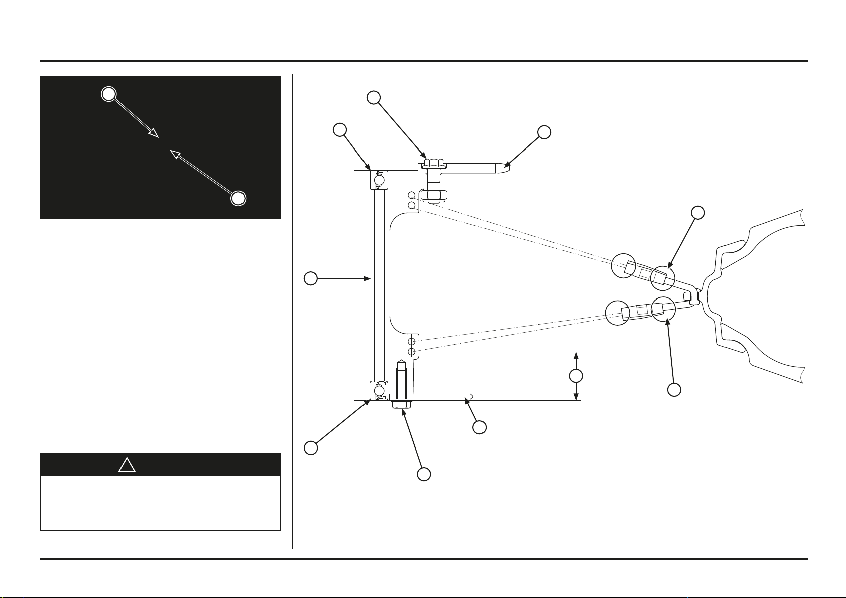
5-15
5-15
Frame servicing
Spokes: Check spoke tension frequently between the first
few rides. As the spokes, spoke nuts and rim contact
points seat-in, the spokes may need to be retightened.
Once past this initial seating-in period, the spokes should
hold their tension. Still, be sure your race maintenance
program includes checking spoke tension and overall
wheel condition on a regular basis.
Rear Wheel
Removal
Raise the rear wheel off the ground and support it with a
block or maintenance stand under the engine.
Remove the following:
– Axle nut and drive chain adjuster
– Drive chain
– Axle, drive chain adjuster and rear wheel
Do not depress the brake pedal after the rear wheel is
removed.
The caliper pistons will move and make reassembly
difficult.
Disassembly/Assembly
!
WARNING
A contaminated brake disc or pad reduces stopping
power, and can cause a serious injury or death.
Discard contaminated pads and clean a contaminated
disc with a high quality brake degreasing agent.
(1) ADJUSTER
(2) AXLE
(1) DRIVEN SPROCKET
(2) DRIVEN SPROCKET BOLT/NUT
(3) LEFT WHEEL BEARING
(4) DISTANCE COLLAR
(5) RIGHT WHEEL BEARING
(6) DISC BOLT
(7) BRAKE DISC
(8) REAR WHEEL NIPPLE
(a) 30 ± 0.5 mm
Drive the bearing
into the hub until it
stops.
7
6
5
4
3
8
8
a
When unassembling change
bolt for new one’s.
Apply a locking agent to the
threads
Torque: 17 N•m (1.7 kgf•m)
3 N.m (0.2 - 0.3 kgf.m)
1
2
32 N•m (3,2 kgf•m)
2
1
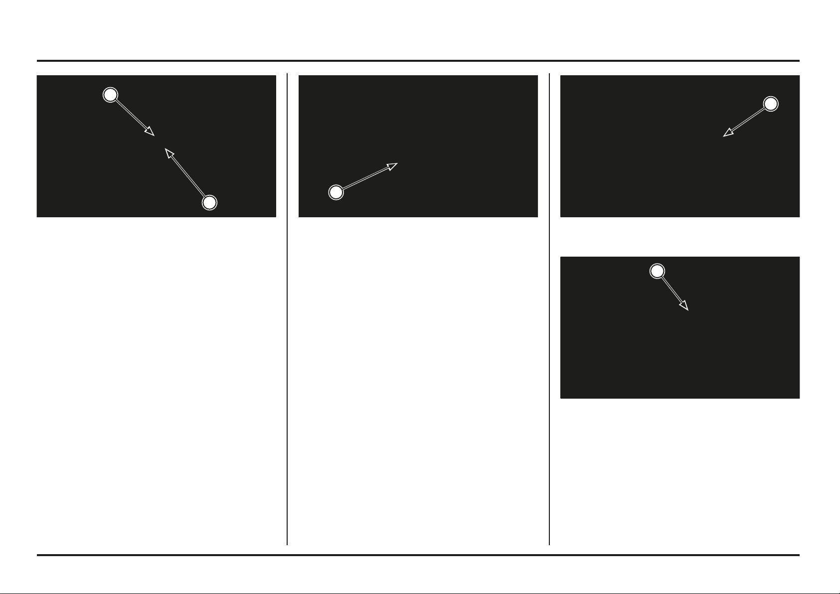
5-16
5-16
Frame servicing
(1) UPPER MOUNTING BOLT/NUT
(2) SHOCK ABSORBER
Shock Absorber
Removal
Remove the air cleaner housing.
Raise the rear wheel off the ground and support it with a
block or maintenance stand under the engine.
Remove the shock absorber lower mounting bolt/nut.
Remove the upper mounting bolt/nut and shock absorber.
(1) LOWER MOUNTING BOLT/NUT
Installation
Install the rear brake caliper aligning with the caliper slide
rail.
Apply thin layer of grease to the axle.
Place the rear wheel between the swingarm being careful
not to damage the disc.
Insert the rear axle into the left chain adjuster, side collar
and wheel.
(1) AXLE
(2) ADJUSTERS
(1) AXLE NUT
Apply grease to the axle nut threads and seating surface.
Install the right chain adjuster and axle nut.
Install the drive chain.
If the master link retaining clip was removed, install the
drive chain with the closed end of the clip in the direction
of wheel rotation.
Check and adjust the drive chain slack (page 3-11).
Tighten the axle nut.
Torque: 69 N•m (7.0 kgf•m, 51 lbf•ft)
1
2
2
1
1
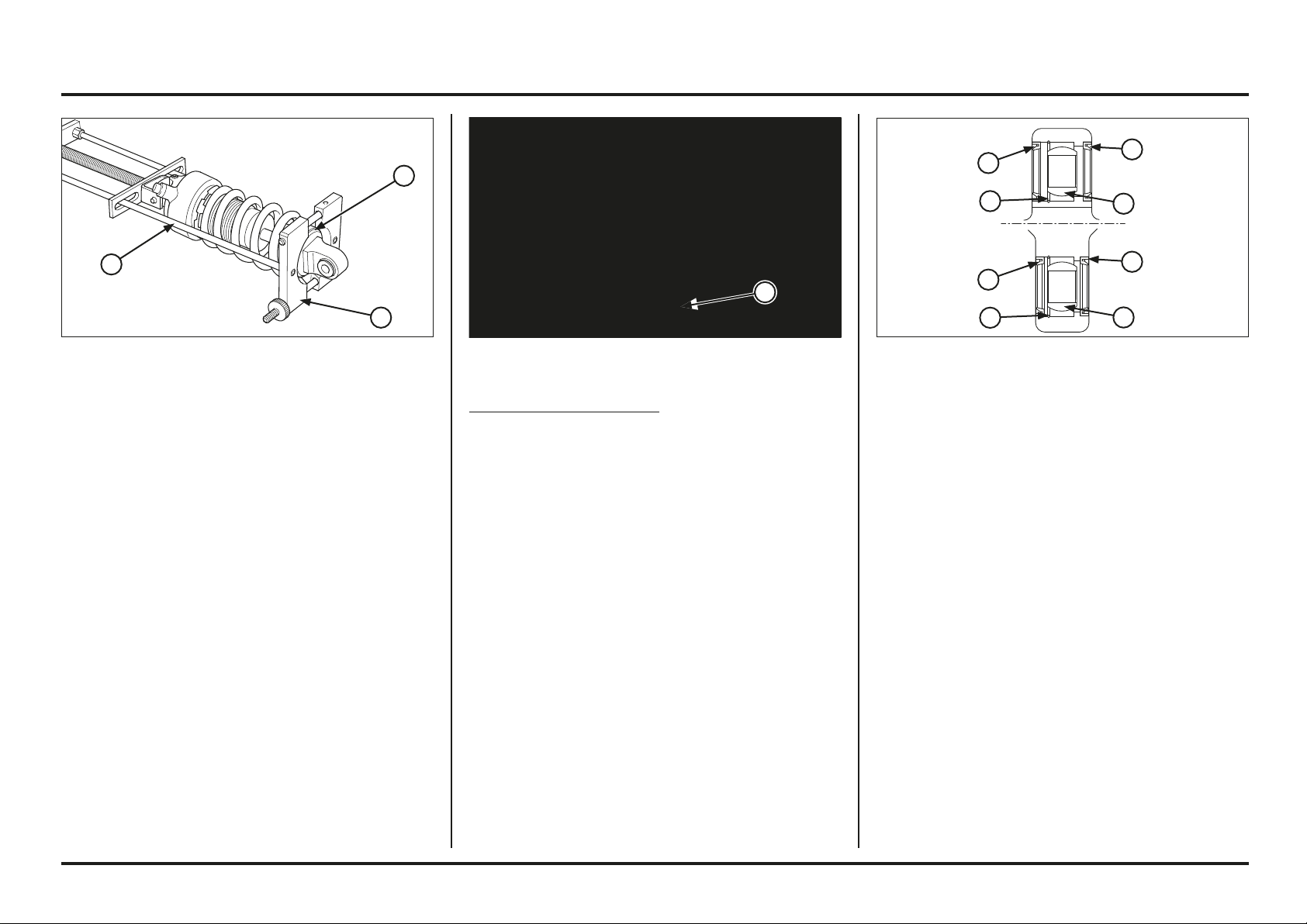
5-17
5-17
Frame servicing
(1) SPRING COMPRESSOR
(2) ATTACHMENT
(3) SPRING SEAT STOPPER
DISASSEMBLY
Loosen the spring lock nut and adjuster.
Remove the lower mounting collars.
Set the shock absorber in the shock absorber compressor
and attachment.
Tools:
Shock absorber compressor 07GME-0010100
– Compressor attachment 07959–MB10000
Remove the stopper ring, spring seat and spring.
Inspection
Check the following items (page 2-4):
– Upper and lower spherical bearing for wear or damage
– Spring for damage and measure the free length
– Damper for oil leakage from the damper rod
– Nitrogen pressure
Replace the damper unit if an oil leak is detected.
(1) VALVE CAP
Nitrogen Releasing Procedure
Remove the air valve cap and press the valve stem and
release the nitrogen from the damper until pressure is
released.
Before disposal of the shock absorber, release the nitrogen
from the damper.
Wear adequate eye protection.
Point the valve away from you to prevent debris getting
into your eyes.
Spherical Bearing Replacement
Remove the collars and dust seals.
Check the spherical bearing for smooth rotation or
damage.
Remove the stop ring
Press the spherical bearing out using the special tool.
Tool:
Spherical bearing driver 07HMF-KS60100
Press a new spherical bearing into the shock absorber
pivot until its seats using same tool.
Install the new stop ring into the groove.
Apply grease to the dust seal lips.
Install the dust seals and collars.
(1) DUST SEALS
(2) STOP RING
(3) SPHERICAL BEARING
1
3
2
1
1
1
1
1
3
3
2
2
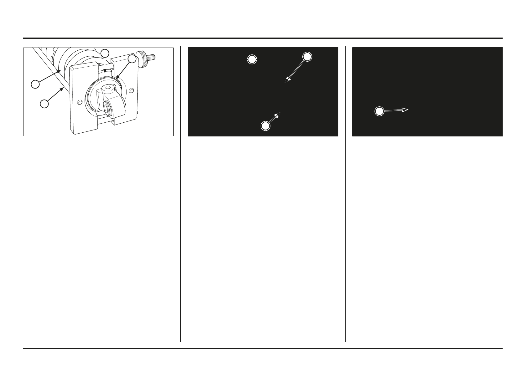
5-18
5-18
Frame servicing
(1) PRE-LOAD LENGTH
(2) ADJUSTER
(3) LOCK NUT
(1) SPRING
(2) SPRING SEAT
(3) STOPPER RING
(4) COMPRESSOR
Assembly
Assembly is in the reverse order of disassembly.
Installation
Set the shock absorber into the frame and install the
upper mounting bolt from the left side.
Install the nut.
(1) UPPER MOUNTING BOLT/NUT
Adjust the spring pre-load length (page 2-4).
Hold the spring adjuster and tighten the lock nut to the
specified torque.
Torque: 49 N•m (5.0 kgf•m)
4
3
2
1
3
2
1
1
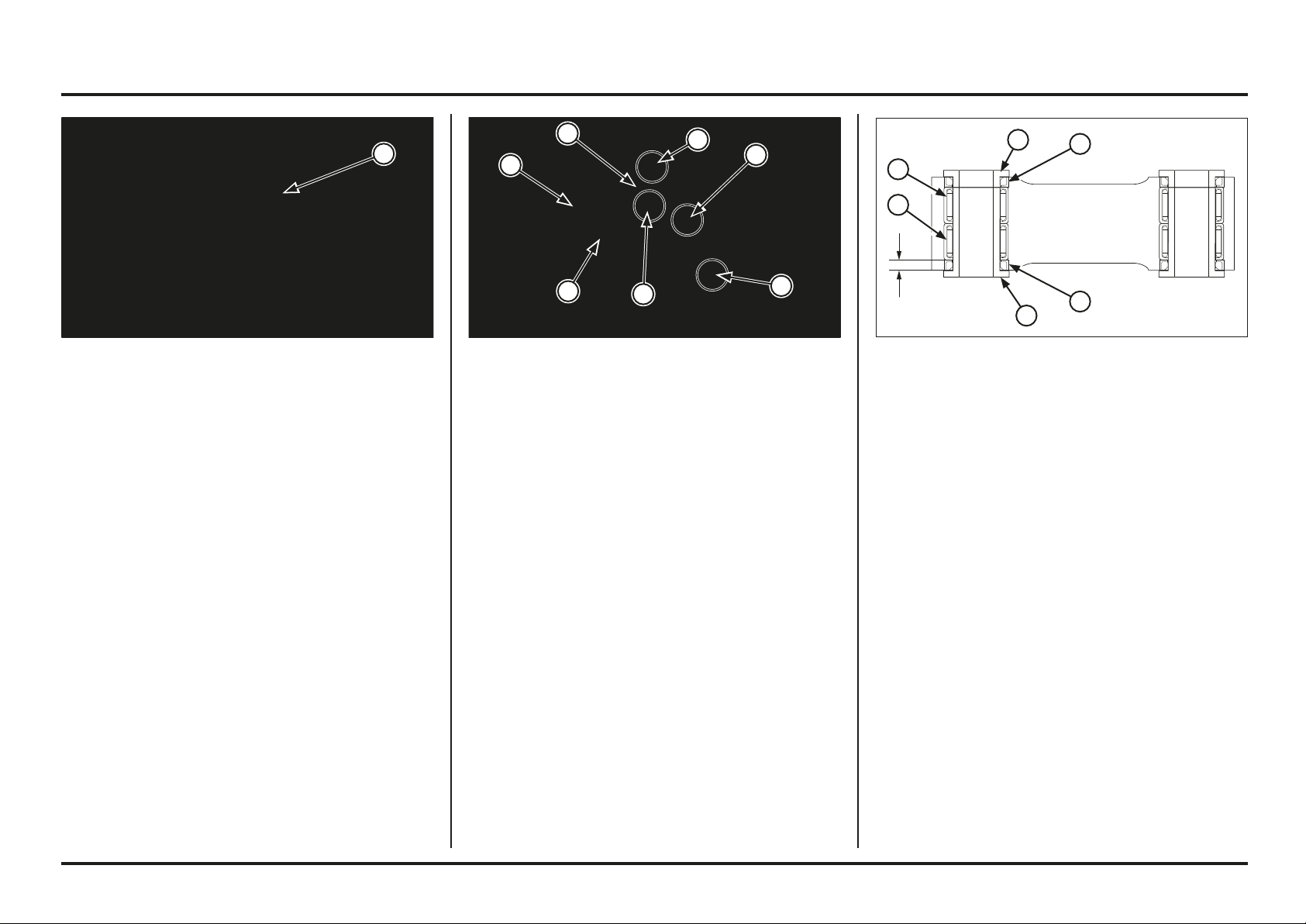
5-19
5-19
Frame servicing
(1) LOWER MOUNTING BOLT/NUT
(2) BOLTS/NUTS
(3) CUSHION ARM PLATES
(4) CUSHION LINK
Shock Linkage
Removal
Raise the rear wheel off the ground with a block or
maintenance stand under the engine.
Remove the following:
– Rear cushion lower mounting bolt/nut
– Cushion arm plate-to-cushion link bolt/nut
– Cushion arm plates-to-swingarm bolt/nut
– Cushion arm plates
– Cushion link-to-frame socket bolt/nut
– Cushion link
Move the swingarm aligning the lower mount, then install
the lower mounting bolt from the right side.
Install and tighten the upper and lower mounting nuts to
the specified torque.
Torque:
Upper mounting bolt: 39 N•m (4.0 kgf•m, 29 lbf•ft)
Lower mounting bolt: 39 N•m (4.0 kgf•m, 29 lbf•ft)
(1) LOWER MOUNTING BOLT/NUT (1) PIVOT COLLAR A
(2) PIVOT COLLAR B
(3) DUST SEALS
(4) NEEDLE BEARINGS
Needle Bearing Replacement
Remove the pivot collars and dust seals.
Check the cushion link needle bearings for damage.
Remove the cushion link needle bearings using the special
tool.
Tool:
Bearing driver 07946-MJ00000
Press new needle bearings into the cushion link to 3 mm
(0.12 in) below the surface of the cushion link using the
special tool, on both sides.
Face the bearing with its marked side facing out.
Tool:
Bearing driver 07946-MJ00000
Apply multi-purpose grease to the collars and dust seal
lips.
Install the dust seals and pivot collars.
3 mm
4
4
3
3
2
1
1
4
3
3
2
1
2
2
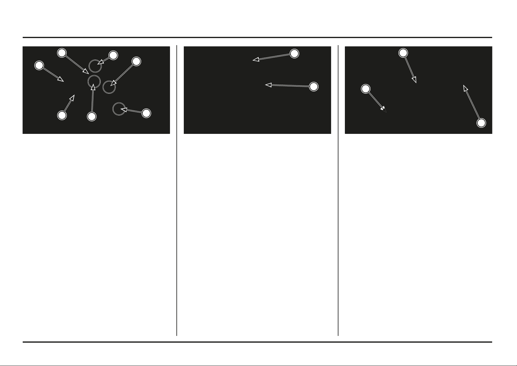
5-20
5-20
Frame servicing
(1) SHOCK ABSORBER LOWER MOUNTING BOLT/NUT
(2) SHOCK ARM PLATES-TO-SWINGARM BOLT/NUT
Swingarm
Removal
Remove the following:
– Rear wheel (page 5-15)
– Shock absorber lower mounting bolt/nut
– Cushion arm plates-to-swingarm bolt/nut
(1) CUSHION LINK
(2) CUSHION ARM PLATES
(3) BOLTS/NUTS
(4) LOWER MOUNTING BOLT/NUT
Installation
Install the following:
– Cushion link
– Cushion link-to-frame socket bolt/nut
– Cushion arm plates
– Cushion arm plates-to-swingarm bolt/nut
– Cushion arm plate-to-cushion link bolt/nut
– Rear cushion lower mounting bolt/nut
Tighten the cushion arm plate and cushion link nuts to the
specified torque.
Torque: 39 N•m (4.0 kgf•m, 29 lbf•ft)
Tighten the rear cushion lower mounting nut to the
specified torque.
Torque: 39 N•m (4.0 kgf•m, 29 lbf•ft)
(1) BRAKE HOSE CLAMPS
(2) SWINGARM PIVOT BOLT/NUT
Remove the following:
– Brake hose clamps screws
– Rear brake caliper
– Swingarm pivot bolt/nut and swingarm assembly
1
2
2
3
4
3
3
2
1
1
2
1

5-21
5-21
Frame servicing
(1) NEEDLE BEARING
(2) DUST SEAL
(3) BUSHING
PIVOT BEARING REPLACEMENT
Replace the swingarm bearings as a set.
Remove the pivot bearings using the special tool.
Tool:
Bearing driver 07946-KA50000
Press a new pivot bearing in using the special tools .
Tools:
Driver 07749-0010000
Attachment, 24 x 26 mm 07746-0010700
Pilot, 20 mm 07746-0040500
Face the bearing with its marked side facing out.
Press the needle bearing so that it is 5.5 mm (0.22 in)
below the swingarm end.
Install the thrust bushings and the dust seal.
(1) DUST SEAL CAP
(2) DUST SEAL
(3) PIVOT COLLAR
(4) DUST SEAL
Disassembly
Remove the following:
– Bolts and drive chain cover
– Bolts and driven sprocket guard
– Screws and drive chain slider
– Chain tensioner
– Dust seal caps
– Dust seals
– Pivot collars
– Thrust bushings
Replace them if they have score marks, scratches,
excessive or abnormal wear.
Check the shock mounts and swingarm for stress, cracks
or other damage.
(1) PIVOT COLLAR A
(2) PIVOT COLLAR B
(3) DUST SEALS
(4) NEEDLE BEARINGS
Link Bearing Replacement
Remove the pivot collars and dust seals.
Remove the pivot bearings using the special tool.
Tool:
Bearing driver 07946-MJ00000
Press a new pivot bearing in using the special tools .
Tool:
Bearing driver 07946-MJ00000
Face the bearing with its marked side facing out.
Press the needle bearing so that it is 3.0 mm (0.12 in)
below the swingarm end.
Install the dust seals and pivot collars.
3 mm
5,5 mm
3
2
1
4
3
2
1
4
3
3
2
1
4
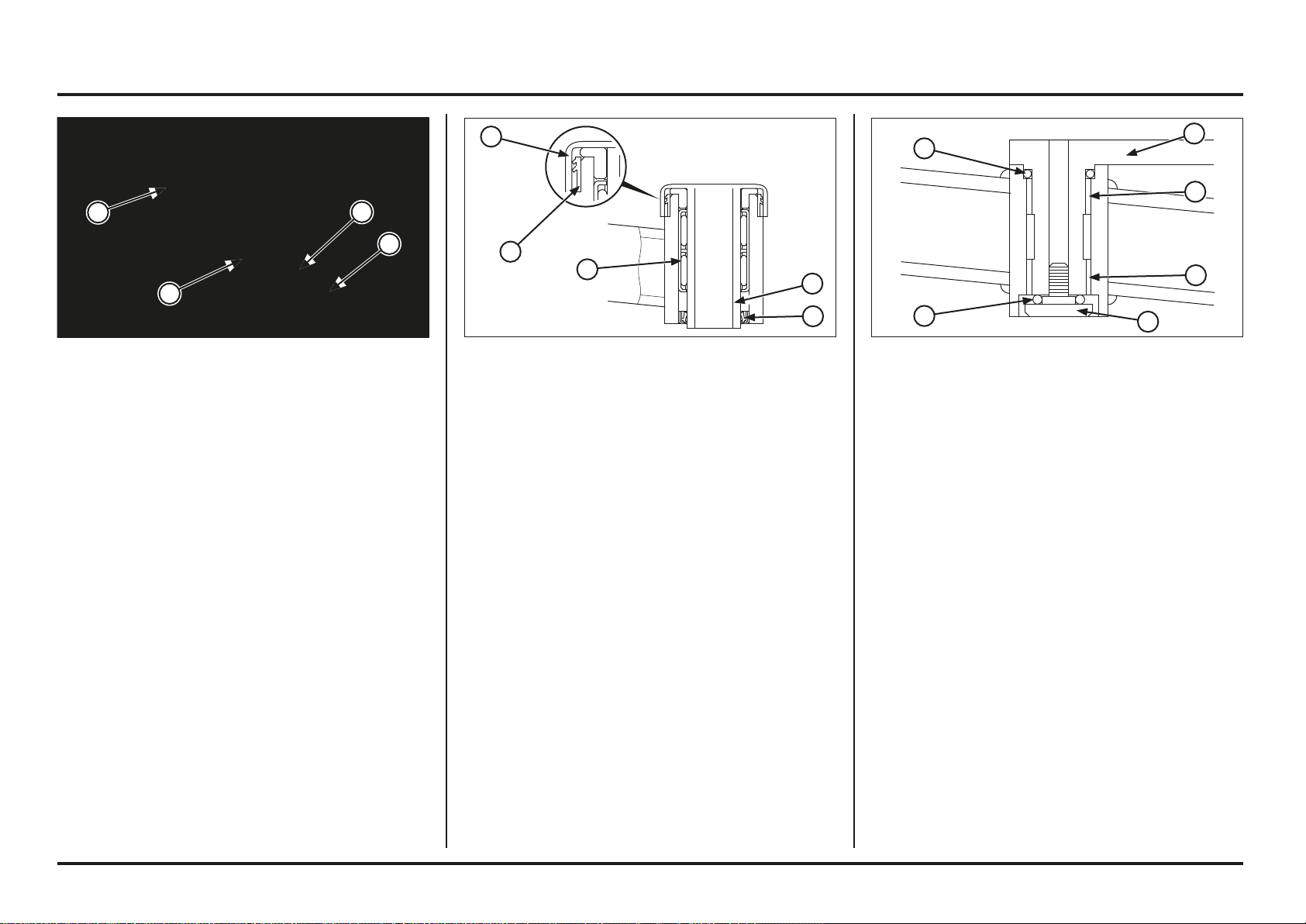
5-22
5-22
Frame servicing
(1) CHAIN TENSIONER
(2) BUSHINGS
(3) O-RINGS
(4) PIVOT BOLT
Apply grease to the pivot chain tensioner, bushings and
O-rings.
Install the drive chain tensioner pivot bushings into the
swingarm.
Install a new O-ring onto the chain tensioner pivot.
Install the chain tensioner into the swingarm.
Install a new O-ring and tighten the pivot bolt.
(1) DUST SEAL
(2) PIVOT COLLAR
(3) DUST SEAL
(4) DUST SEAL CAP
(5) NEEDLE BEARING
Install the pivot collars, dust seals and dust seal caps.
Note the direction of the dust seal.
(1) DUST SEAL
(2) PIVOT COLLAR
(3) DUST SEAL
(4) DUST SEAL CAP
Assembly
Apply grease to the bearings, pivot collars and lips of a
new dust seals.
5
4
3
2
1
1
2
3
4
4
3
3
2
2
1
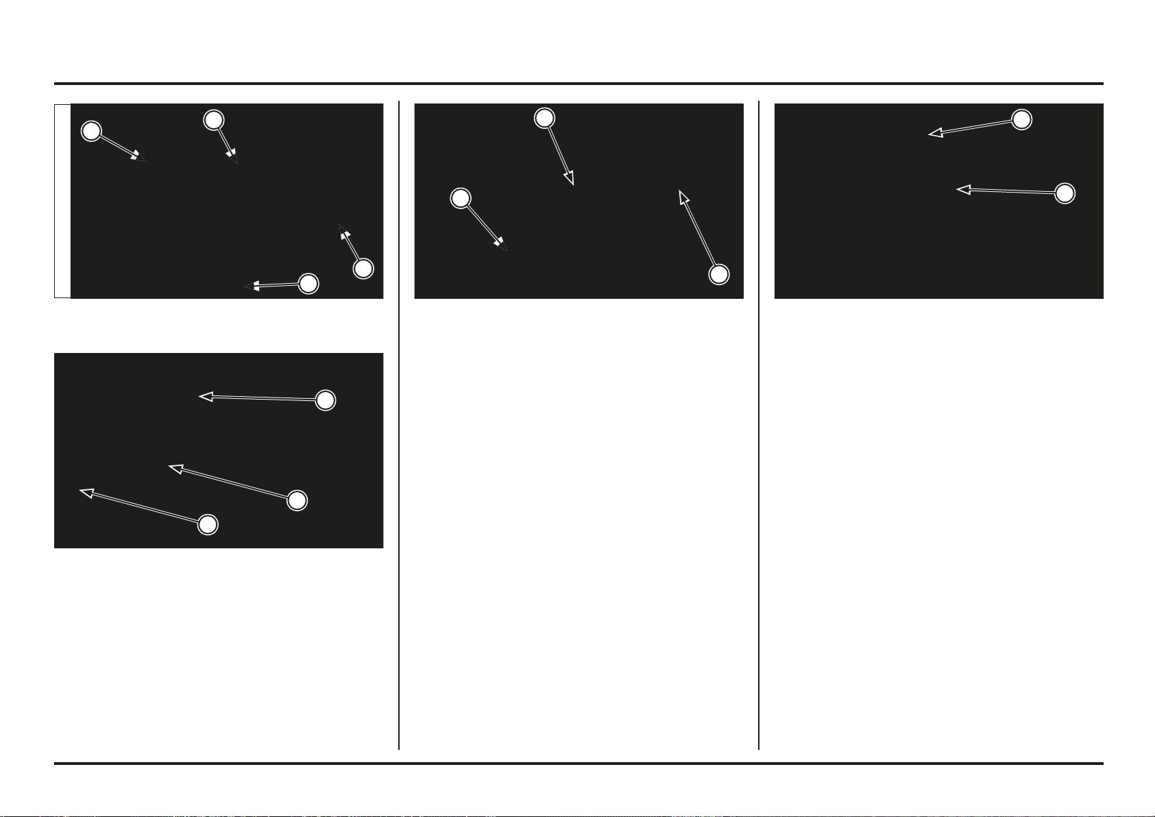
5-23
5-23
Frame servicing
(1) SHOCK ARM PLATES-TO-SWINGARM BOLT/NUT
(2) SHOCK ABSORBER LOWER MOUNTING BOLT/NUT
Installation
Apply thin coat of grease to the swingarm pivot bolt
surface.
Install the swingarm into the frame.
Install the swingarm pivot bolt from the left side.
Install and tighten the swingarm pivot nut to the specified
torque.
Torque: 69 N•m (7.0 kgf•m, 51 lbf•ft)
Install the brake caliper onto the swingarm rail.
Install the brake hose clamps and tighten the screws.
(1) PIVOT BOLT/NUT
(2) HOSE CLAMPS
(1) DRIVE CHAIN GUARD
(2) SCREWS
Install the drive chain sliders onto the swingarm.
Apply a locking agent to the drive chain slider screw
threads and tighten the screw.
Install the drive chain guard and tighten the bolts.
Torque: 6 - 7 N•m (0.6 - 0.7 kgf•m)
(1) DRIVE CHAIN SLIDER
(2) SCREWS
Install the following:
– Shock arm plates-to-swingarm bolt/nut
– Rear cushion lower mounting bolt/nut
Tighten the shock arm plate bolt.
Torque: 39 N•m (4.0 kgf•m, 29 lbf•ft)
Tighten the shock absorber lower mounting bolt to the
specified torque.
Torque: 39 N•m (4.0 kgf•m, 29 lbf•ft)
Install the rear wheel (page 5-16)
2
2
2
2
2
1
2
1
2
1
1
2
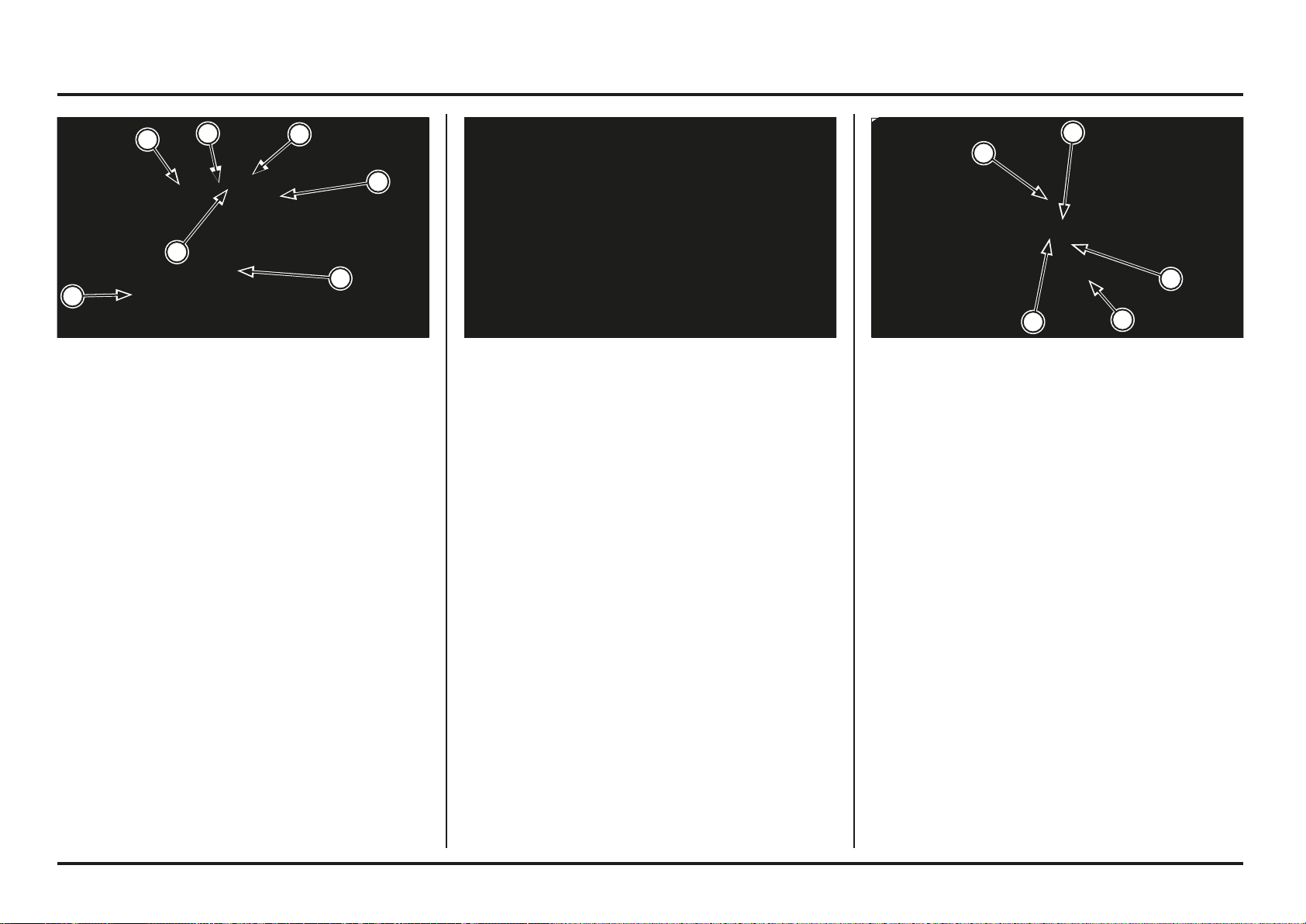
5-24
5-24
Frame servicing
(1) NEW PADS
(2) PAD SPRING
(3) PIN
(4) CIRCLIP
Install the new pads, the spring from the pads and secure
with the pad pin and the circlip.
Torque: 8 N•m (0.8 kgf•m, 5.9 lbf•ft)
Install the caliper to the fork so the disc is positioned
between the pads, being careful not to damage the pads.
Apply a locking agent to the caliper mounting bolt threads.
Install the disc cover, then install and tighten the mounting
bolts.
Torque: 26 N•m (2.7 kgf•m, 20 lbf•ft)
Operate the brake lever to seat the caliper pistons against
the pads.
Push the pistons all the way in to allow installation of new
brake pads.
Check the brake fluid level in the reservoir as this operation
causes the level to rise.
Remove the brake pads.
Clean the brake caliper inside especially around the caliper
pistons.
(1) PAD SPRING PIN
(2) BOLTS
(3) DISC COVER
(4) CALIPER
Front Brake Pad Replacement
Clean the brake disc with a high quality degreasing agent
if they are contaminated with oil or grease.
Replace the pads if they are contaminated.
Remove the brake caliper mounting bolts, disc cover,
flange collars and caliper.
Remove the circlip.
Remove the pad pin.
Remove the spring from the pads.
2
1
1
4
3
3
2
2
1
6
4
5
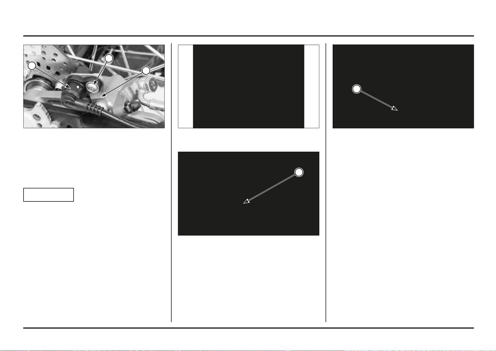
5-25
5-25
Frame servicing
(1) BRAKE PADS
(2) PAD PIN
Remove the pad pin and brake pads.
Clean the brake caliper inside especially around the caliper
pistons.
(1) CALIPER PISTON
Remove the rear wheel (page 5-15)
Push the piston all the way in to allow installation of new
brake pads.
Check the brake fluid level in the reservoir as this operation
causes the level to rise.
(1) BOLT
(2) SPEED SENSOR
(3) SPEED SENSOR BRACKET
Rear Brake Pad Replacement
Clean the brake disc with a high quality degreasing agent
if they are contaminated with oil or grease.
Replace the pads if they are contaminated.
NOTICE
Before replacing the rear brake pads, remove the speed
sensor.
The speed sensor may be damaged if struck or pulled.
Speed sensor removal (2ED)
Remove the following:
– Speed sensor bolt
– Remove the sensor from the sensor mount.
Detach the speed sensor from the rear brake calliper for
easier removal.
1
1
3
2
1
2ED
2ED
5-26
5-26
Frame servicing
(1) BRAKE HOSE OIL BOLT
(2) MOUNTING BOLTS
(3) DISC COVER
(4) BRAKE CALIPER
Front brake caliper
Removal
NOTICE
Avoid spilling brake fl uid on painted, plastic or rubber
parts.
Place a shop rag over these parts whenever the system
is serviced.
Drain the brake system.
Place a clean container under the caliper.
Remove the following:
– Brake hose oil bolt
– Sealing washers
– Brake hose eyelet
– Caliper mounting bolts
– Disc cover
– Flange collars
– Brake caliper
– Spring pin for the pads
– Brake pads (page 5-24)
Install the brake caliper bracket aligning its slit with the
boss on the swingarm.
Install the rear wheel (page 5-16).
Operate the brake pedal to seat the caliper pistons against
the pads.
(1) CALIPER PISTON(1) CALIPER BRACKET
(2) BOSS/SLIT
Install the new pads and secure them with the pad pin.
2
1
2
1
4
3
2
2
1
5-27
5-27
Frame servicing
Inspection
Clean the inside of the caliper.
Check the oil leakage from the caliper cylinder.
If any part of the caliper is damaged, replace the caliper
as an assembly.
Installation
Install the brake caliper onto the swingarm rail.
Connect the brake hose with two new sealing washers.
Install the rear wheel (page 5-16).
Tighten the oil bolt to the specified torque.
Torque: 26 N•m (2.7 kgf•m, 20 lbf•ft)
Bleed the air in the rear brake system.
(1) CALIPER PISTON
Rear brake caliper
Removal
NOTICE
Avoid spilling brake fl uid on painted, plastic or rubber
parts.
Place a shop rag over these parts whenever the system
is serviced.
Drain the brake system.
Place a clean container under the caliper.
Remove the following:
– Brake hose oil bolt
– Sealing washers
– Brake hose eyelet
– Rear wheel (page 5-15)
– Brake caliper/bracket
– Spring pin for the pads
– Brake pads (page 5-25)
(1) OIL BOLT
(2) BRAKE HOSE
(3) BRAKE CALIPER
Inspection
Clean the inside of the caliper.
Check the oil leakage from the caliper cylinders.
If any part of the caliper is damaged, replace the caliper
as an assembly.
Installation
Apply locking agent to the caliper mounting bolt threads.
Install the brake caliper and disc cover, and then install
and tighten the caliper mounting bolts.
Torque: 26 N•m (2.7 kgf•m, 20 lbf•ft)
Connect the brake hose with two new sealing washers,
then tighten the oil bolt.
Torque: 20 N•m (2.0 kgf•m, 14.6 lbf•ft)
Bleed the air in the front brake system.
1
3
2
1
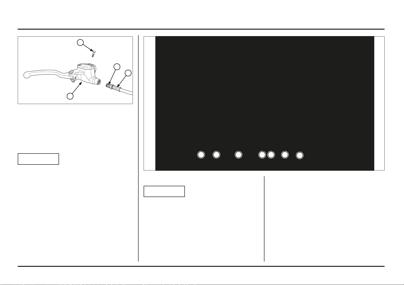
5-28
5-28
Frame servicing
(1) OIL BOLT
(2) BRAKE HOSE
(3) BOLT
(4) HOLDER
(5) MASTER CYLINDER
Front master cylinder
Removal/Installation
NOTICE
Avoid spilling brake fl uid on painted, plastic or rubber
parts. Place a shop rag over these parts whenever the
system is serviced.
When removing the brake hose bolt, cover the end of
the hoses to prevent contamination. Secure the hoses
to prevent fl uid from leaking out.
Drain the brake fluid from the hydraulic system into a
suitable container.
Remove the following:
– Brake lever
– Brake hose bolt
– Master cylinder holder bolt and holder
– Master cylinder
Inspection
Check the following items (page 2-4):
– Master cylinder and piston for scoring, scratches or
other damage
– Master piston O.D. and master cylinder I.D.
Installation
Installation is in the reverse order of removal.
Torque:
Brake hose oil bolt:
14 N•m (1.4 kgf•m, 10.3 lbf•ft)
Master cylinder holder bolt:
5.5 N•m (0.5 kgf•m, 4.1 lbf•ft)
Bleed the air in the front brake system.
Disassembly/Assembly
NOTICE
Keep the master cylinder piston, oil seals, spring and
snap ring as a set; don’t substitute individual parts.
When installing the oil seals, do not allow the lips to
turn inside out and be certain the snap ring is fi rmly
seating in the groove.
Remove the snap ring and disassemble the master
cylinder.
(1) BOOT
(2) SNAP RING
(3) PISTON ASSEMBLY
(4) SPRING
(5) OIL SEAL
(6) CIRCLIP
4 3 25 6
1
5
4
3
2
1
5-29
5-29
Frame servicing
(1) OIL BOLT
(2) BRAKE HOSE
(3) MASTER CYLINDER
(1) BOLTS
(2) MASTER CYLINDER
(1) NUT
(2) BOLT
(3) BRAKE PEDAL
Rear master cylinder
Removal/Installation
NOTICE
Avoid spilling brake fl uid on painted, plastic or rubber
parts. Place a shop rag over these parts whenever the
system is serviced.
When removing the brake hose bolt, cover the end of
the hoses to prevent contamination. Secure the hoses
to prevent fl uid from leaking out.
Drain the brake fluid from the hydraulic system into a
suitable container.
Remove the air cleaner housing.
Remove the exhaust muffler.
Remove the reservoir tank from the bracket.
Remove the brake hose oil bolt and disconnect the brake
hose.
Remove the mounting bolts and master cylinder.
Installation
Installation is in the reverse order of removal.
Connect the brake hose with two new sealing washers,
then tighten the oil bolt.
Torque:
Brake hose oil bolt: 26 N•m (2.7 kgf•m, 19.1 lbf•ft)
Bleed the air from the rear brake system.
Brake pedal
Removal
Remove the brake pedal pivot nut and bolt.
Remove the brake pedal and collar.
3
2
1
2
1
1
3
2
1
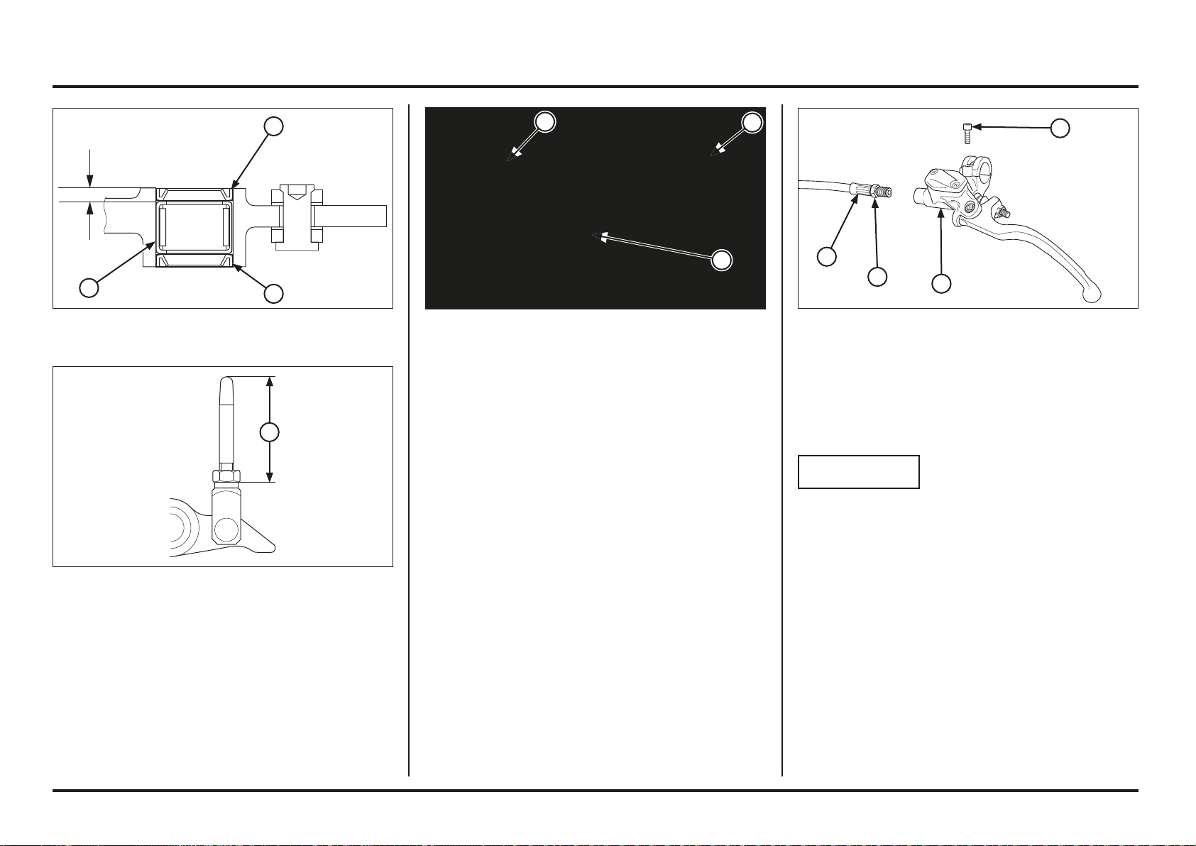
5-30
5-30
Frame servicing
(1) OIL BOLT
(2) CLUTCH HOSE
(3) BOLT
(4) HOLDER
(5) MASTER CYLINDER
Clutch master cylinder
Removal/Installation
NOTICE
Avoid spilling brake fl uid on painted, plastic or rubber
parts. Place a shop rag over these parts whenever the
system is serviced.
When removing the clutch hose bolt, cover the end of
the hose to prevent contamination. Secure the hose
to prevent fl uid from leaking out.
Drain the clutch fluid from the hydraulic system into a
suitable container.
Remove the following:
– Clutch lever
– Clutch hose bolt
– Master cylinder holder bolt and holder
– Master cylinder
Installation
Install the brake pedal and collars.
Install and tighten the pivot nut and bolt.
Apply sealant to the threads of pivot bolt.
Torque: 29 N•m (3.0 kgf•m, 22 lbf•ft)
(1) COLLAR B
(2) PEDAL
(3) COLLAR A
(1) STANDARD LENGTH; 35 MM
Pivot Bearing Replacement
Remove the dust seals.
Remove the pivot bearing and press a new needle bearing
so that it is 3 mm (0.12 in) below the pedal end. Apply
grease inside needle bearing.
Adjust the brake pedal height by loosening the lock nut
and turning the push rod.
Push rod height must be adjusted between 32.5–37.5 mm.
(1) BEARING
(2) DUST SEALS
3 mm (0.12 in)
2
2
1
1
3
2
1
4
3
2
1
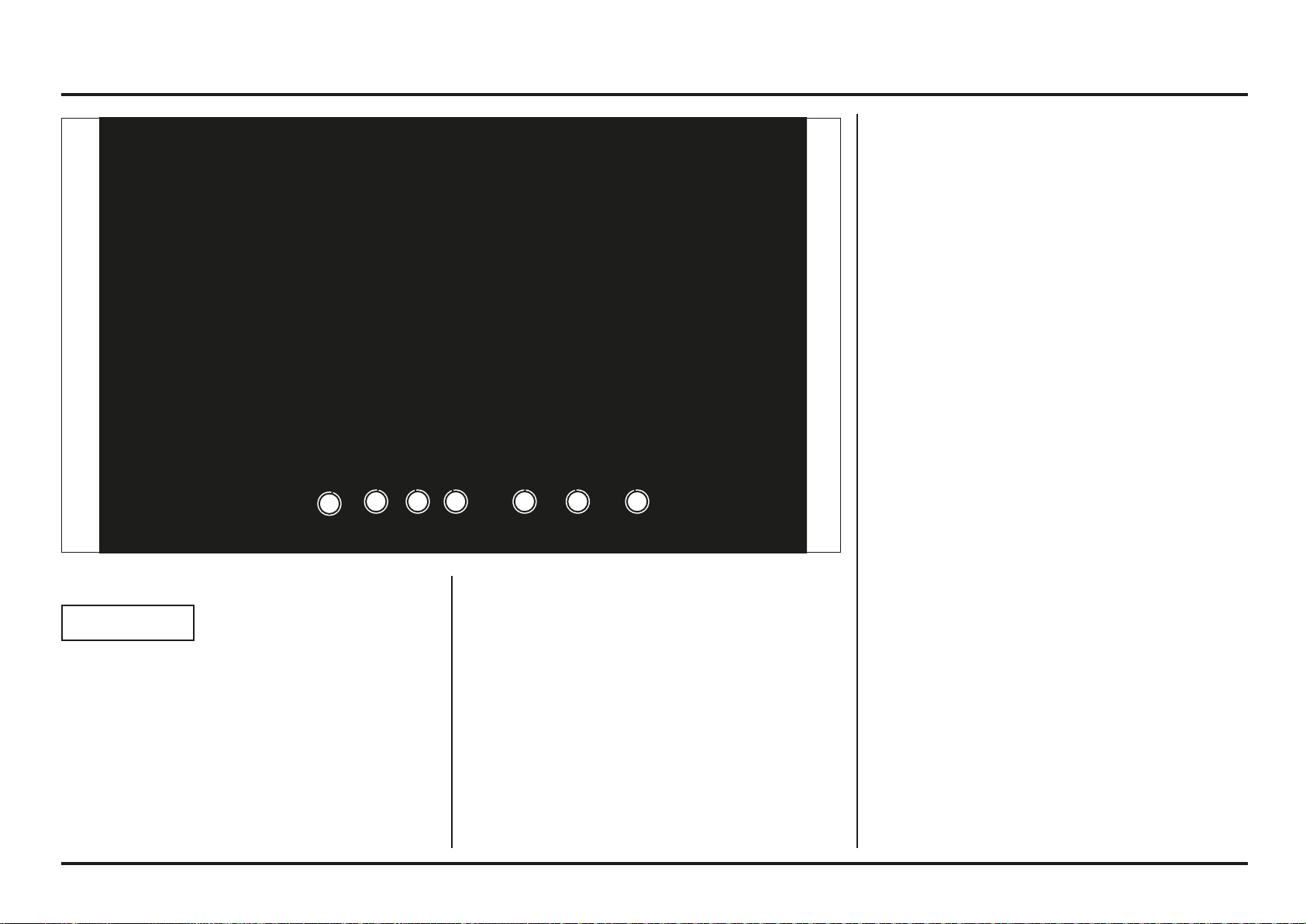
5-31
5-31
Frame servicing
Disassembly/Assembly
NOTICE
Keep the master cylinder piston, oil seals, spring and
snap ring as a set; don’t substitute individual parts.
When installing the oil seals, do not allow the lips to
turn inside out and be certain the snap ring is fi rmly
seating in the groove.
Remove the snap ring and disassemble the master
cylinder.
Inspection
Check the following items (page 2-3):
– Master cylinder and piston for scoring, scratches or
other damage
– Master piston O.D. and master cylinder I.D.
Installation
Installation is in the reverse order of removal.
Torque:
Brake hose oil bolt: 14 N•m (1.4 kgf•m, 10.3 lbf•ft)
Master cylinder holder bolt: 5.5 N•m (0.5 kgf•m, 4.1 lbf•ft)
Bleed the air from the clutch system.
(1) BOOT
(2) SNAP RING
(3) PISTON ASSEMBLY
(4) SPRING
(5) OIL SEAL
(6) CIRCLIP
432 56
1
5

5-32
5-32
Memo
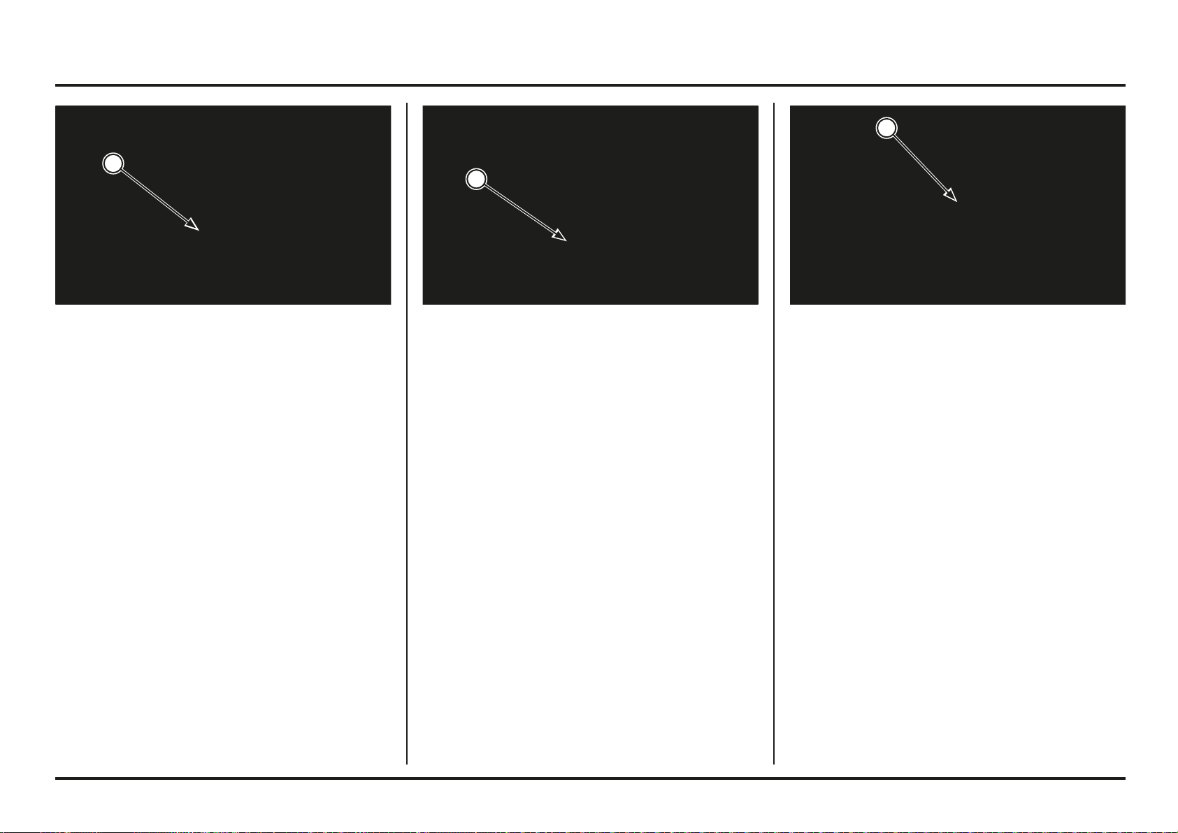
6-1
6-1
(1) 6P (BLACK) CONNECTOR (1) 3P (NATURAL) CONNECTOR (1) 4P (NATURAL) CONNECTOR
Charging system inspection
Alternator charging coil
Disconnect the regulator rectifier 6P (Black) connector.
Measure the resistance between the Yellow terminals of
the wire harness side.
Standard: 0.7 – 1.0 (20˚C/68˚F)
If the resistance is out of specification, disconnect the
alternator 3P (Natural) connector and measure the
resistance between the yellow terminals of the alternator
side connector.
If the measured resistance at regulator/rectifier 6P (Black)
connector is incorrect and the alternator 3P (Natural)
connector is correct, check the wire harness.
If the resistance is still out of specification, replace the
stator assembly.
Regulated Voltage Inspection
Disconnect the power 4P (Natural) connector.
Connect the digital voltmeter to the Red (+) and Green
(–) terminals.
Start the engine, check for regulated voltage.
Standard: 13.5 – 14.5 V/1,800 min-1 (rpm)
6. Electrical servicing
1
1
1
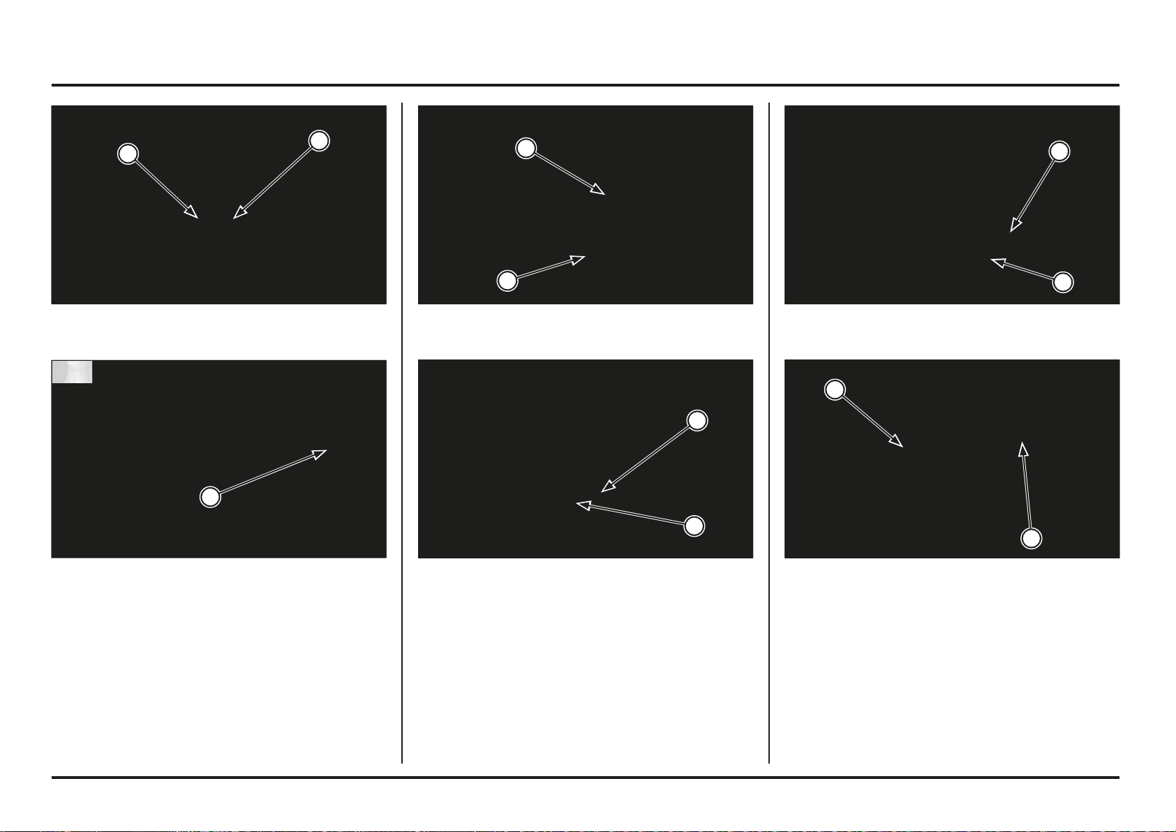
6-2
6-2
Electrical servicing
(1) 3P (NATURAL) CONNECTOR
(2) 2P (NATURAL) CONNECTOR
(1) 2P (BLACK) CONNECTOR
(2) 6P (BLACK) CONNECTOR
(1) BOLTS
(2) ELECTRICAL COMPONENTS SUPPORT
(1) FAN MOTOR RELAY
Regulator/Rectifier Removal/installation
Remove the throttle body (page 4-13).
Disconnect the alternator 3P (Natural) connector and
ignition pulse generator 2P (Natural) connector.
Remove the fan motor relay from the bracket.
(1) BOLT
(2) BRAKE RESERVOIR
Disconnect the condenser 2P (Black) and regulator/
rectifier 6P (Black) connectors.
Remove the rear brake reservoir tank mounting bolt.
(1) 2P (BLACK) CONNECTOR
(2) CONDENSER
Remove the electrical components support bolts, then
remove the electrical components support from the frame.
Release the condenser 2P (Black) connector, then remove
the condenser from the electrical components support.
2
1
2
1
2
1
2
1
2ED
2ED
1
2
1
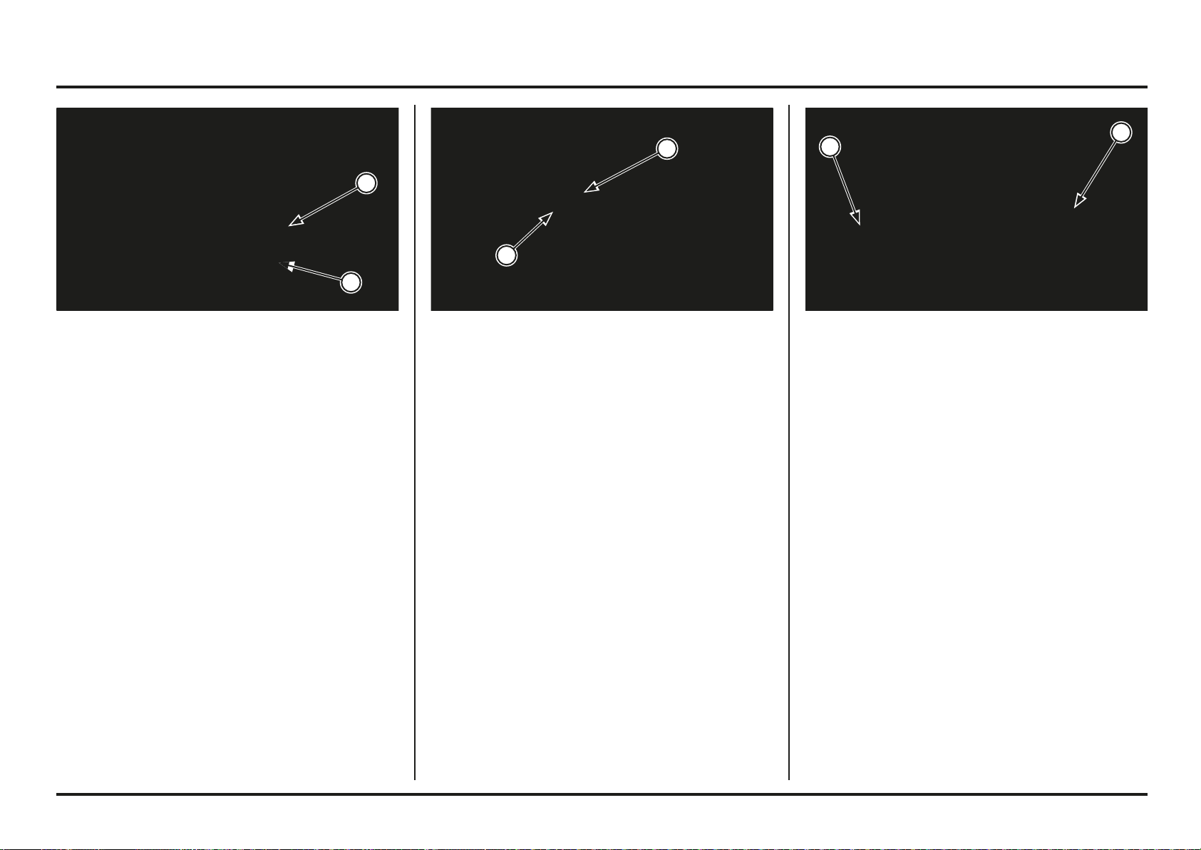
6-3
6-3
Electrical servicing
Ignition coil Removal/Installation
Remove the fuel tank/injector assembly.
Remove the spark plug cap.
Remove the tie-wrap and release the spark plug wire from
the fan motor bracket.
(1) SPARK PLUG CAP
(2) TIE-WRAP
Ignition system inspection
Ignition coil inspection
Disconnect the wires from the ignition coil of the terminals
and measure the ignition primary coil resistance between
the primary terminals.
Standard: 2.6 - 3.2 (20˚C/68˚F)
Measure the secondary coil resistance.
Standard:
With plug cap: 17.3 - 22.8 k (20˚C/68˚F)
Without plug cap: 13.5 - 16.5 k (20˚C/68˚F)
Replace the ignition coil if the resistance is out of
specification.
(1) PRIMARY TERMINALS
Remove the bolts and regulator/rectifier from the electrical
components support.
Install the regulator/rectifier and condenser in the reverse
order of removal.
Install the rest of the components in the reverse order of
disassembly.
(1) BOLTS
(2) REGULATOR/RECTIFIER
1
1
2
1
1
2
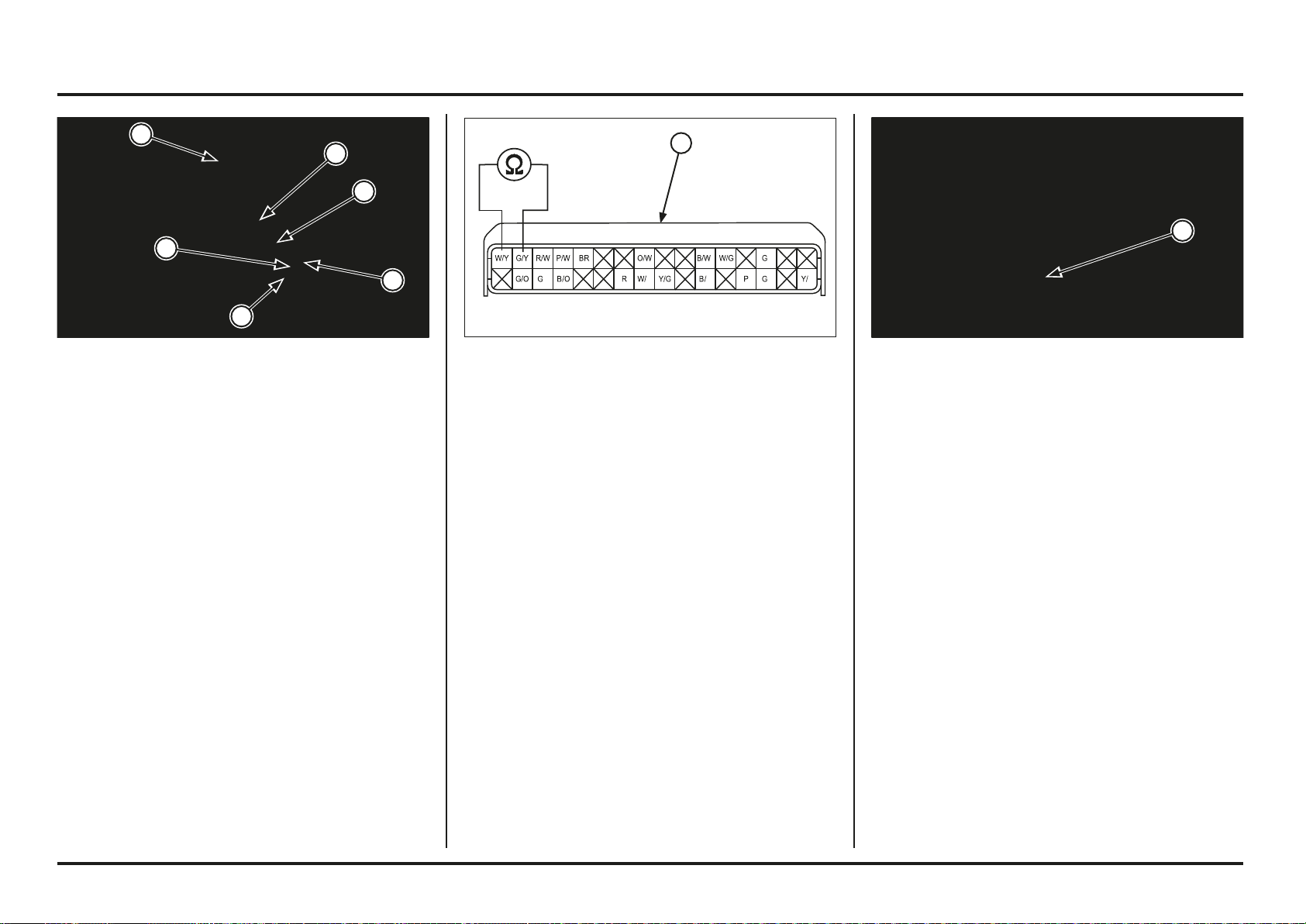
6-4
6-4
Electrical servicing
L LL
1
2
1
If the resistance is out of specification, measure the
resistance at the ignition pulse generator 2P (Natural)
connector.
If the measured resistance at ECM 32P (Black) connector
is incorrect and the ignition pulse generator 2P (Natural)
connector is correct, check the wire harness.
If the resistance is still out of standard, replace the ignition
pulse generator/stator assembly (page 4-52).
(1) 2P (NATURAL) CONNECTOR
Ignition Pulse Generator Inspection
Check the resistance of the pulse generator power in the
32P (Black) connector (page 6-5).
Connection: White/yellow – Green/yellow
Standard: 85 - 115 (20˚C/68˚F)
(1) 32P (BLACK) CONNECTOR(1) WIRE CLAMP
(2) PRIMARY WIRES
(3) BOLTS
(4) IGNITION COIL
Remove the wire clamp.
Disconnect the primary wires from the ignition coil.
Remove the mounting bolts and ignition coil.
Installation is in the reverse order of removal.
Route the spark plug wire properly and secure it with
tiewrap.
1
4
3
3
2
2
1
1

6-5
6-5
Electrical servicing
PGM-FI System inspection
Place the motorcycle upright position and remove the rear fender.
Disconnect the ECM 32P (Black) connector.
Check for the following at the ECM terminals of the wire harness side.
Item Terminal Standard
Ignition pulse generator G/Y – W/Y 85 – 115 Ω (20˚C/68˚F)
Ignition coil (primary coil) Y/L – R 2.6 – 3.2 Ω (20˚C/68˚F)
INJ (Injector) P – R 11.1 – 12.3 Ω (20˚C/68˚F)
Engine stop switch B/W – Ground Continuity exist only when switch is pushed
ECT (Engine Coolant Temperature) sensor P/W – G/O 2.3 – 2.6 kΩ (20˚C/68˚F)
Sensor ground G1 – Ground Continuity
Power ground G1 – Ground Continuity
(1) 32P (BLACK) CONNECTOR
Condenser Inspection
If the engine does not start, check for the items “engine
does not start” in the PGM-FI Malfunction Indicator Lamp
(MIL) Failure Code chart on page 6-9.
If all items are correct, replace the condenser unit with
new one, and inspect again.
If the engine starts, the replaced condenser is faulty.
If the engine does not starts, check for wire harness.
(1) CONDENSER
1
1
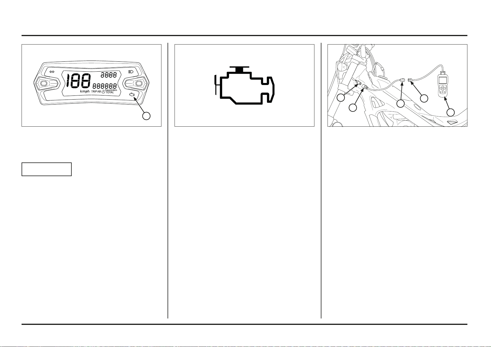
6-6
6-6
Electrical servicing
(1) MALFUNCTION INDICATOR (MIL)
PGM-FI
NOTICE
If the MIL indicator comes on while driving, you may
have a problem with the PGM-FI electronic injection sys-
tem.
Slow down and stop the motorcycle in a safe place.
Re-start the motorcycle.
If the MIL indicator is still on after 5 seconds, inspect the
motorcycle at your Montesa dealer as soon as possible.
OBD system (diagnosis system)
This motorcycle complies with the Euro 4 standard and
with the OBD diagnosis system phase1. The existing
PGM-FI injection system is equipped with a self-diagnosis
system. When there is an anomaly in the injection sys-
tem, the engine control module (ECM) turns on the engine
trouble indicator (MIL) and stores an error code (DTC) in
its memory. With the OBD diagnosis system, a generic
diagnostic tool (DST) available in shops can be connected
to consult and clear the DTC error codes and the frozen
data.
(1) 4P OBD (RED) (4) OBD CONNECTOR
(2) 4P CONNECTOR (5) DST
(3) 16P CONNECTOR
Connection of a generic diagnosis tool (DST)
The DTC error codes read by the generic diagnostic tool
(DST), follow the format of the ISO standard and the con-
nector of the DST is also the 16-pin of the ISO standard.
Therefore, in order to connect the generic diagnosis tool
(DST) to the motorcycle, it is necessary to use an adapter
(reference 070MZ-K530101) for the 4-pin OBD connector
(red), which is located behind the headlight housing.
To use the DST, refer to the instruction manual included
with the purchased model.
Connect the diagnostic tool (DST) as shown in the
illustration and start the motorcycle.
Check the active DTC codes and confirm the error code
in the code list on page “MIL and DTC (ISO) error codes
of the PGM-FI electronic injection system” on page 6-9.
Stop the motorcycle and solve the fault.
Start the motorcycle and with the help of the DST proceed
to erase the fault codes stored in the speedometer.
Once the speedometer failure codes have been eliminated
with the DST, even if it is not necessary, it is recommended
to also delete the codes stored in the ECM (see page 6-7).
Fail-safe function
The PGM-FI system is provided with a fail-safe function to
secure a minimum running capability even when there is
trouble in the system. When any abnormality is detected
by the self-diagnosis function, running capability is main-
tained by pre-programmed value in the simulated program
map. When any abnormality is detected in the injector,
the fail-safe function stops the engine to protect it from
damage.
MIL Check
When the engine is started the MIL will stay on for 5
seconds and then go off. If the MIL does not come off,
troubleshoot DTC code. If the MIL does not come on,
troubleshoot the MIL circuit.
1
5
4
3
2
1
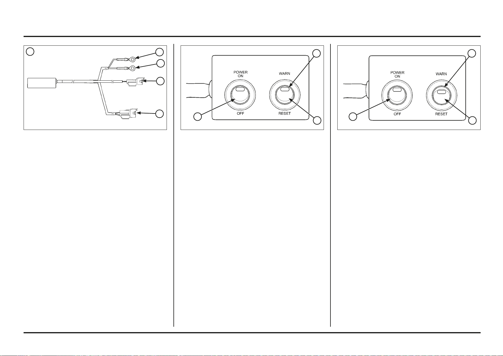
6-7
6-7
Electrical servicing
(1) PGM WARNING UNIT ASSEMBLY
(2) RED WIRE EYELET
(3) GREEN WIRE EYELET
(4) 2P (BLACK) CONNECTOR
(5) 4P (RED) CONNECTOR
DTC readout procedure
– Disconnect the fuel pump 2P (Black) connector.
– Disconnect the condenser 2P (Black) connector and
connect the warning unit 2P (Black) connector to the
wire harness side.
Tool:
PGM-FI warning unit assembly 38880-NN4-H00
– Make sure PGM-FI warning unit assembly power switch
is in OFF position.
– Connect the waring unit 4P (Red) connector to the ser-
vice check 4P (Red) connector.
– Connect the fully charged 12 V battery to the warning
unit terminals (red wire eyelet to the battery positive
terminal and green wire eyelet to the negative termi-
nal).
(1) POWER SWITCH
(2) MIL
(3) WARN/RESET SWITCH
– Turn the PGM warning unit “WARN/RESET” switch to
the warning side as shown.
– Turn the power switch ON, check that the MIL.
– If the ECM has no self diagnosis memory data, the MIL
will illuminate, when you turn the power switch ON.
– If the ECM has self diagnosis memory data, the MIL
will start blinking when you turn the power switch ON.
– Note how many times the MIL blinks, and determine
the cause of the problem (See page 6-9).
(1) POWER SWITCH
(2) MIL
(3) WARN/RESET SWITCH
Self-diagnosis Reset Procedure
– Connect the PGM-FI warning unit assembly to the wire
harness and 12 V battery same procedure as Self-diag-
nosis (see previous step).
– Before turn ON the power switch, turn the warning/
reset switch to the warning side.
– Turn the power switch ON, then turn the warning/reset
switch to reset side.
– The MIL lights about 5 seconds.
While the MIL lights, turn the warning/reset switch to
the warning side.
– Self-diagnosis memory data is erased, if the MIL turns
off and start blinking.
The “WARN/RESET” switch must be switched to
“WARN” side while the indicator lights. If not, the MIL
will not sart blinking
Note that the self-diagnosis memory data cannot be
erased if you disconnect the battery from the warning
unit assembly before the MIL starts blinking.
PGM-FI Self-diagnosis Malfunction Indicator Lamp
(MIL) Failure Codes
5
4
3
2
1
3
2
1
3
2
1
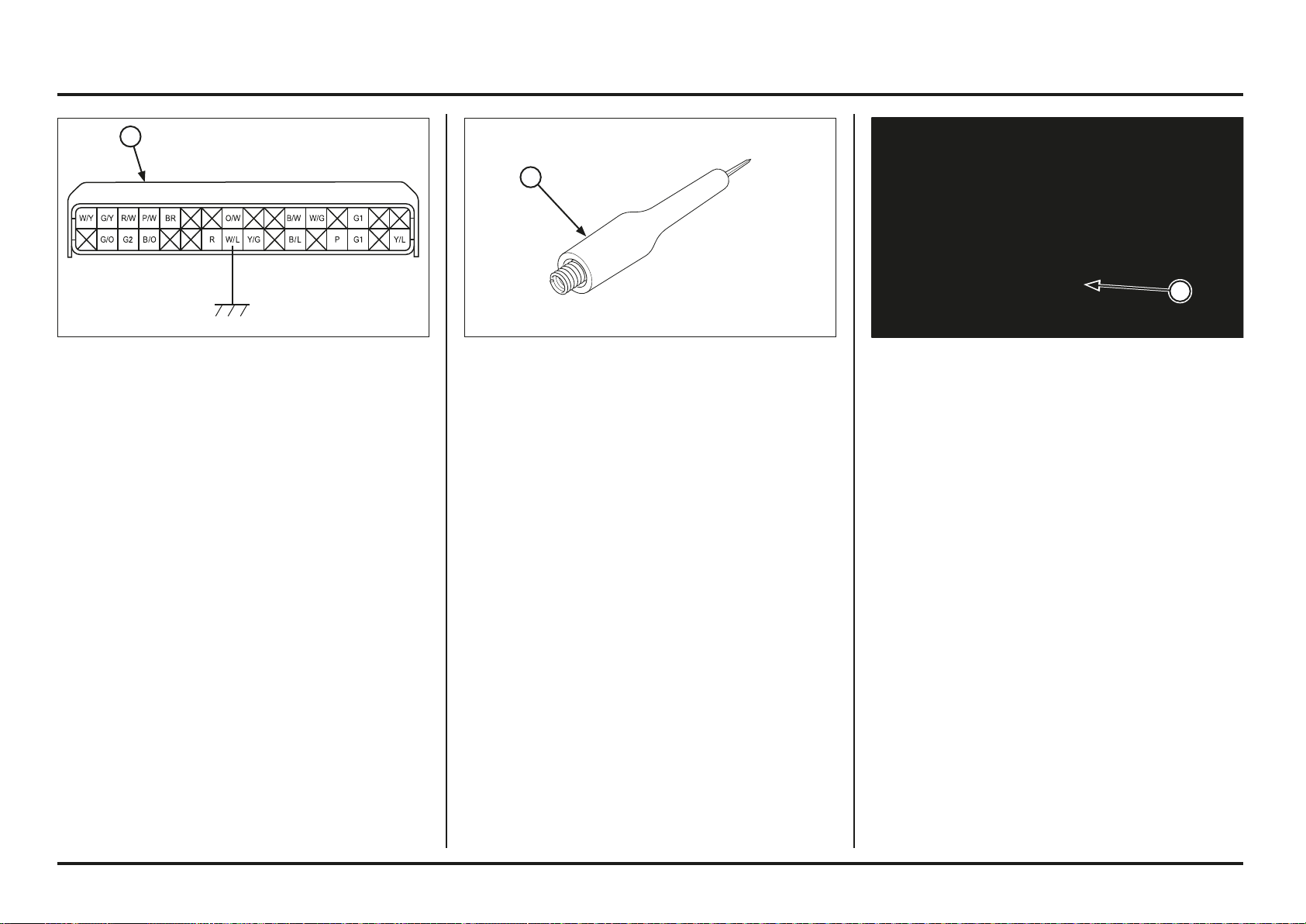
6-8
6-8
Electrical servicing
– Start the engine the MIL should come on.
If the MIL comes on, replace the ECM with a known
good one and recheck the MIL indication.
If the MIL does not come on, check for open circuit
between green wire terminal of MIL 4P (White) connec-
tor and White/blue wire terminal of the wire harness
side ECM 32P (Black) connector.
If the wire is OK, replace the combination meter.
Tool:
Test probe 07ZAJ-RDJA110
(1) 4P (WHITE) CONNECTOR(1) PROBE
Mil circuit troubleshooting
If the MIL does not come on when the engine start, check
as follows:
– Stop the engine
– Disconnect the ECM 32P (Black) connector
– Ground the White/blue wire terminal of the wire har-
ness side ECM 32P (Black) connector with a jumper
wire
(1) 32P CONNECTOR GENERAL INSTALLATION
1
1
1

6-9
6-9
Electrical servicing
MIL and DTC (ISO) error codes for the PGM-FI injection system.
The PGM-FI MIL denotes the failure codes (the number of blinks from 0 to 54). When the indicator lights for 1.3 seconds, it is equivalent to ten blinks. For example; a 1.3 second
illumination and two blinks (0.5 second x 2) of the indicator equals 12 blinks. Follow code 12 troubleshooting.
When more than one failure occurs, the MIL shows the blinks in the order of lowest number to highest number. For example; if the indicator blinks once, then seven times, two
failures have occurred. Follow codes 1 and 7 troubleshooting.
Number
of blinks
(*)
ISO
error codes
(**)
Causes Symptoms
0 No blinks Faulty ECM Engine does not start
No blinks Faulty ECM (PGM-FI warning indicator output) Engine operates normally
Stay lit Short circuit in service check connector
Faulty ECM (PGM-FI warning indicator output)
Engine operates normally
1 Blink P0160 Open or short circuit in MAP sensor line (in the ECM)
Faulty MAP sensor
Poor idle
7 Blinks P0116 Loose or poor contact on ECT sensor
Open or short circuit in ECT sensor wire
Faulty ECT sensor
Hard starting at a low temperature
(Simulate using numerical values; 90 ˚C/194˚F)
Cooling fan does not stop
8 Blinks P0121 Open or short circuit in TP sensor line (in the ECM)
Faulty TP sensor
Poor engine response when operating the throttle quickly
(Simulate using numerical values; throttle open 0˚)
9 Blinks P0111 Open or short circuit in IAT sensor line (in the ECM) Engine operates normally
(Simulate using numerical values; 25˚C/77˚F)
12 Blinks P0200 Loose or poor contact on injector connector
Open or short circuit in injector wire
Faulty injector
Engine does not start
21 Blinks P0130 Loose or poor contact on O2 sensor
Open or short circuit in O2 sensor wire
Faulty O2 sensor
Engine operates normally
54 Blinks P1000 Loose or poor contact on bank angle sensor connector
Open circuit in bank angle sensor wire
Faulty bank angle sensor
Engine starts but stops after few seconds.
(*) Warning unit
(**) Generic diagnosis tool (DST)
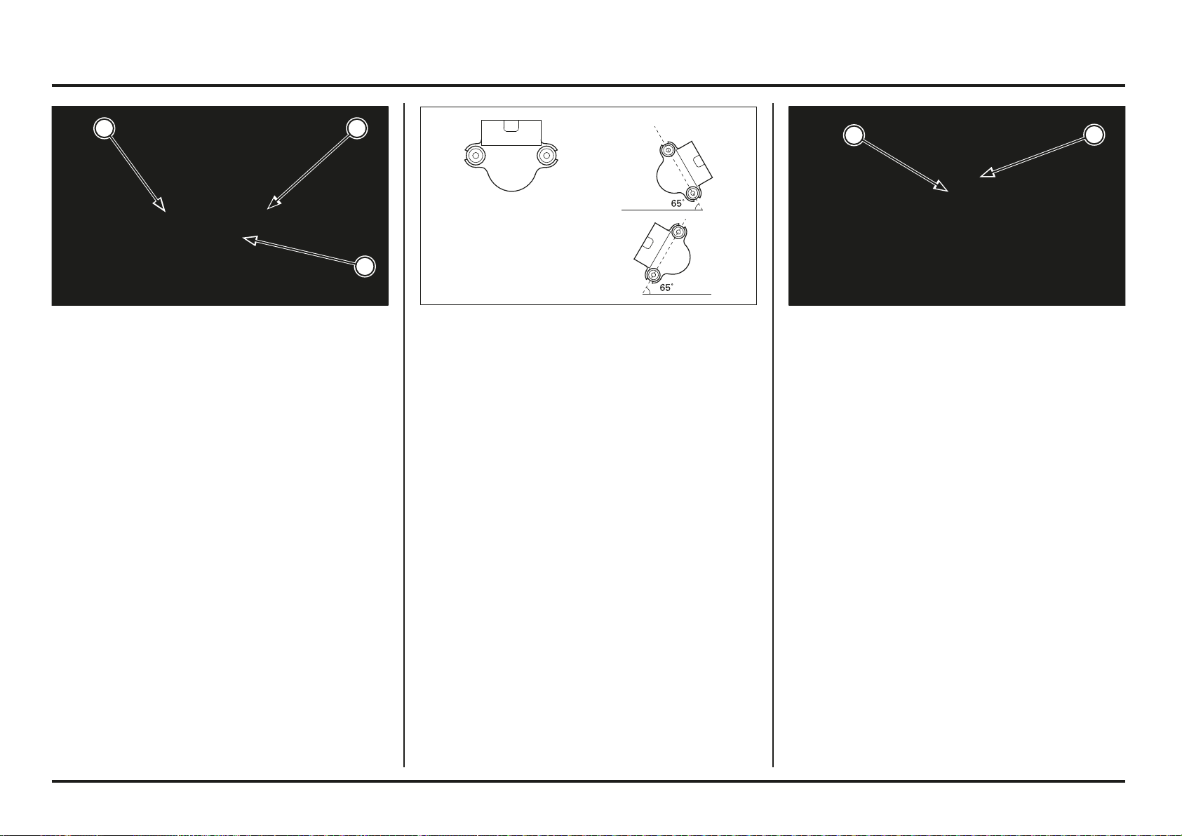
6-10
6-10
Electrical servicing
Install the bank angle sensor in the reverse order of
removal.
Install the bank angle sensor with its arrow/UP mark
facing up as shown.
(1) ARROW/UP MARK
(2) BANK ANGLE SENSOR
Connect the bank angle sensor 3P (Natural) connector.
With the arrow mark on the bank angle sensor facing up,
start the engine.
Incline the bank angle sensor approximately 65 degrees
to the left or right, make sure that the engine stops after
few seconds.
If the engine stops, the bank angle sensor is normal.
If the engine does not stop, replace the bank angle sensor.
With the arrow/UP mark on the bank angle sensor facing
up again, restart the engine.
The engine starts, the bank angle sensor is normal.
Bank angle sensor inspection
Remove the electric stay assembly from the frame (page
6-2).
Remove the screws and bank angle sensor from the
sensor bracket.
(1) SCREWS
(2) BANK ANGLE SENSOR
1 1
2
2
1
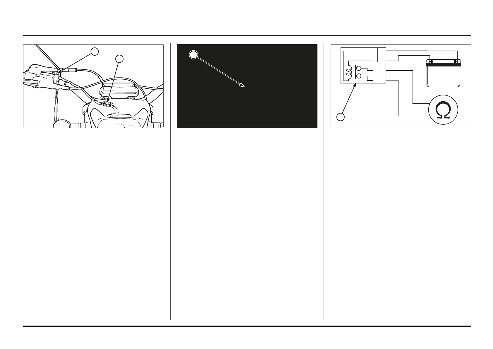
6-11
6-11
Electrical servicing
Fan motor relay inspection
Remove the fan motor relay.
Connect the ohmmeter to the fan motor relay connector
terminals.
Connection: Red – Blue
Connect the 12 V battery to the following fan motor relay
terminals.
Connection: Red – Black/Blue
There should be continuity only when the 12 V battery is
connected.
If there is no continuity when the 12 V battery is
connected, replace the fan motor relay.
(1) FAN MOTOR RELAY
Cooling fan system inspection
Fan motor inspection
Remove the fuel tank.
Disconnect the fan motor 2P (Natural) connector.
Directly connect the 12 V battery to the fan motor 2P
(Natural) connector terminals of the fan motor side.
The fan motor is correct when the fan motor operate
when the 12 V battery is connected.
If the fan motor does not operate, replace the fan motor
assembly.
(1) 2P (NATURAL) CONNECTOR
Magnetic engine stop switch inspection
Disconnect the magnetic engine stop switch connectors.
Check the magnetic engine stop switch for continuity.
There should be continuity when the magnetic switch top
part (magnet) is removed.
Replace the switch if it is out of specification.
(1) MAGNETIC ENGINE STOP SWITCH
(2) CONNECTORS
2
1
1
1
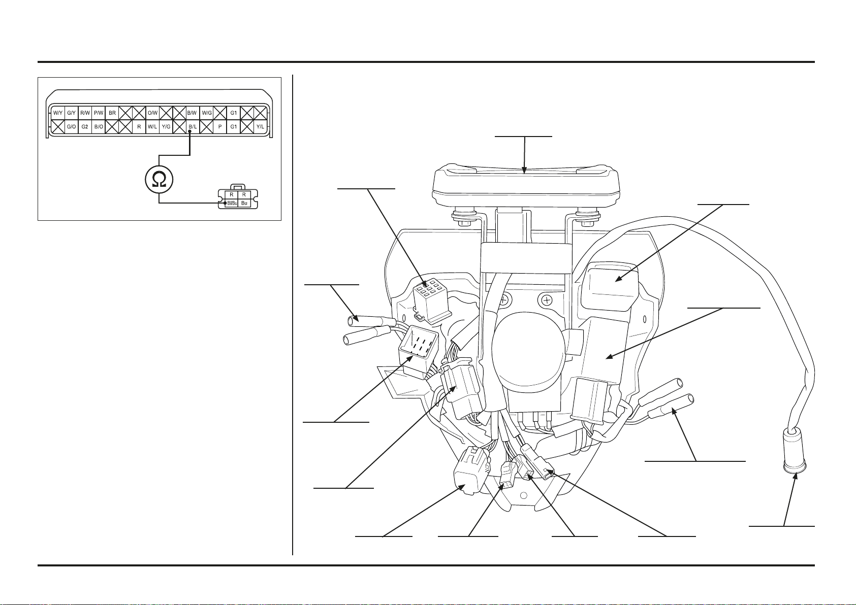
6-12
6-12
Electrical servicing
Wire harness inspection
Check for continuity of the Black/Blue wire between the
fan motor relay 2P (Natural) connector and ECM 32P
(Black) connector.
There should be continuity.
If there is no continuity, repair or replace the wire harness.
Chapter lights / instruments / switches (2ED)
System location
Speedometer
Winker relay
Right rear turn signal
connectors
Lighting
switch
9P connector
Sub-installation
9P connector
MIL 2P
connector
OBD
4P connector
Speedometer
6P connector
Left rear
turn signal
connectors
Front stop
switch
connector
Speed sensor
3P connector
2P connector
(inactive)
Power relay
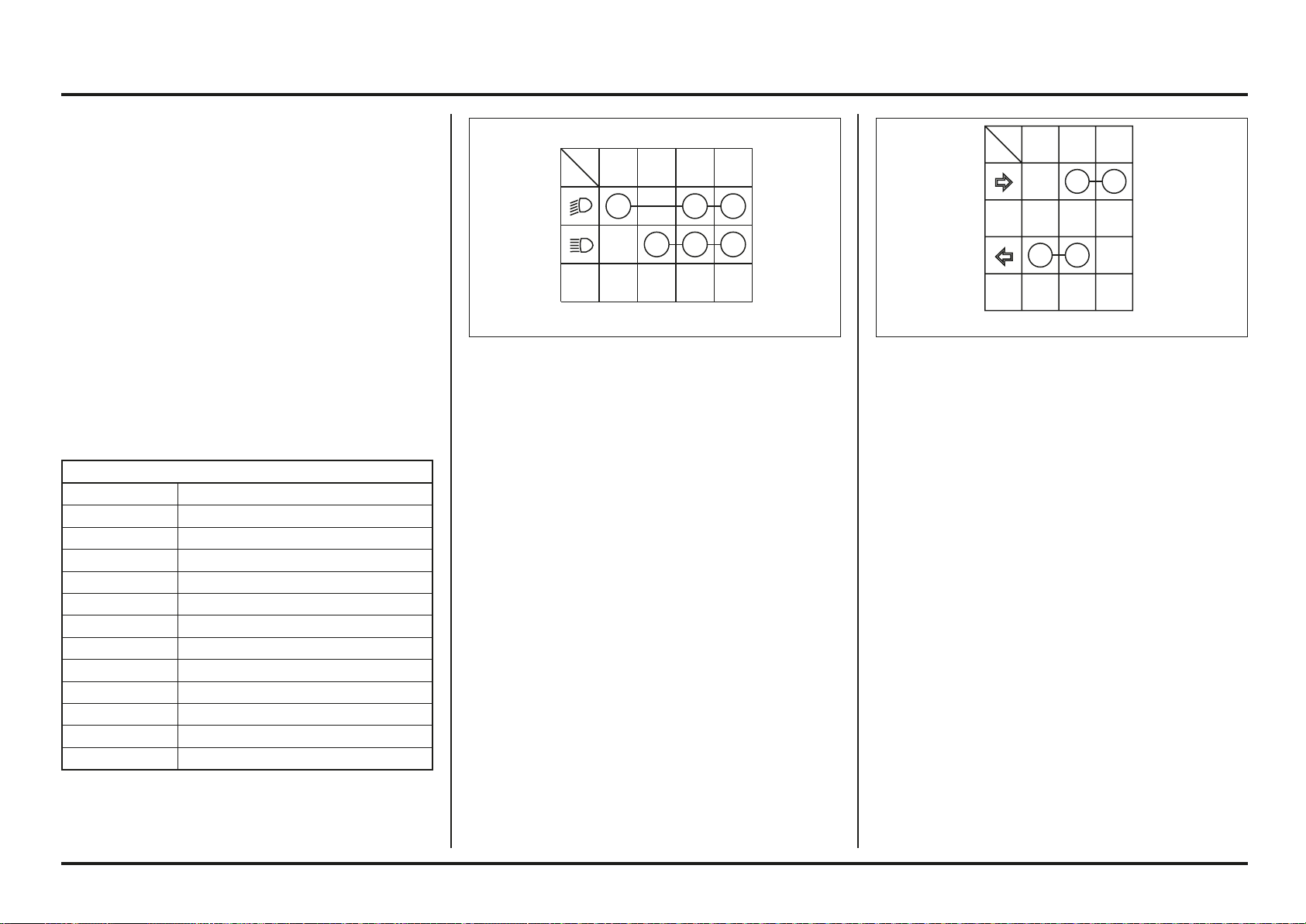
6-13
6-13
Electrical servicing
Indicator light/Indicator light relay.
Checks:
If the engine starts but the indicator lights do not work,
check the following:
Bulb blown or not of the specified wattage.
Loose connector.
Operation of the indicator light switch:
Remove the housing for the upper headlight.
Disconnect the connector 9P from the left switch on the
handlebar.
Check the continuity between the terminals in each
switch position, as shown in the table.
If the previous elements are working properly, remove
the housing for the upper headlight and disconnect the
connector 2P white from the indicator light relay.
Start the engine and check the voltage between the
following terminals of the connector on the harness side:
Connection: RBlack (+) – Ground (–)
Standard: 12V approximately.
If there is no voltage, check the following:
Open circuit in the RBlack wire between the indicator
light relay 2P (white) and the ignition relay.
Checks:
If the engine starts but the front headlight or the position
light do not work, check the following:
Bulb blown or not of the specified wattage.
Loose connector.
Start the engine and check the voltage between the
following terminals of the connector 9P (white) on the
harness side:
Connection: Black (+) – Ground (–)
Standard: 12V approximately.
If there is no voltage, check the following:
Open circuit in the black wire between the ignition
relay and the connector 9P (white) on the handlebar.
If there is voltage, disconnect the connector 9P from the
left switch on the handlebar.
Check the continuity between the terminals in each
switch position, as shown in the table.
Servicing information
Bear in mind the following when replacing the front
headlight bulb.
- Use clean gloves when replacing the bulb. Do not
touch the front headlight bulb with your fingertips,
since this could produce hot spots on the bulb and
cause it to break.
- If you touch the bulb with your bare hands, clean it
with a cloth moistened with alcohol to prevent its
early failure.
Ensure that you replace the dust cover after changing
the front headlight bulb.
The bulb for the front headlight gets very hot when it is
on and remains hot for a while after the front headlight
has been turned off. Ensure that you leave it to cool
before carrying out any maintenance work.
Continuity checks can be carried out using the switches
on the motorcycle.
The following colour codes are used throughout this
section.
COLOUR CODES
B Black
Y Yellow
L Blue
G Green
R Red
W White
V Violet
BR Brown
O Orange
SB Light blue
LG Light green
P Pink
GR Grey
Y/G
COLOR
N
R/B L/R
LW
R
INTERRUPTOR DE INTERMITENTES
Lo Hi
BAT
Po
W
COLOR
LBBR
INTERRUPTOR DE LUCES
LIGHTING SWITCH
TURN SIGNAL SWITCH
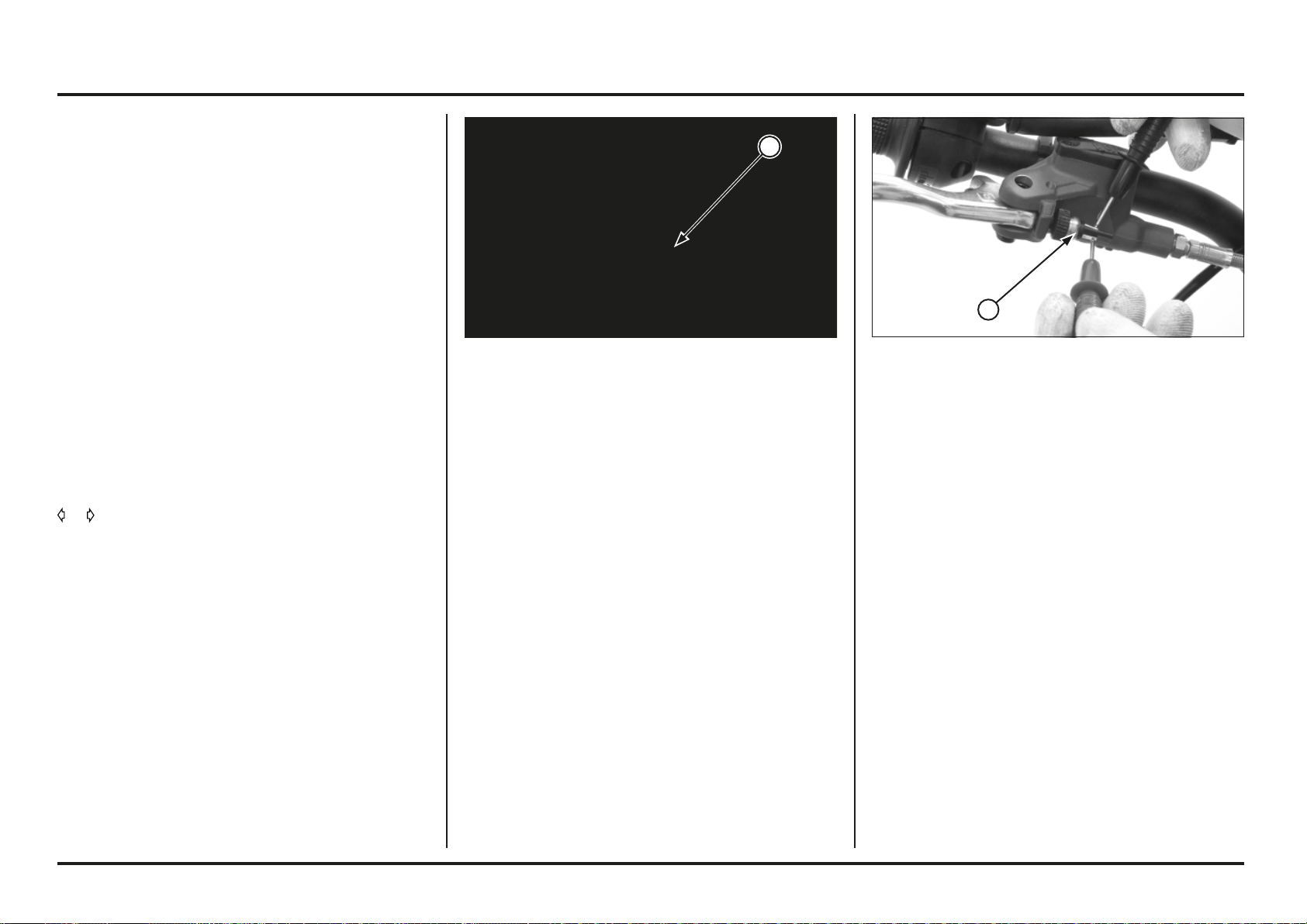
6-14
6-14
Electrical servicing
(1) 2P CONNECTOR FOR THE BRAKE LIGHT SWITCH(1) BRAKE LIGHT LAMP
Checking indicator line:
Connect, when shorted, the terminals of the connector
2P (white) of the indicator relay with a jumper wire.
Connection: RBlack – Black
Start the engine and move the indicator switch to position
or .
Check that the indicator lights are working.
If the indictor lights come on, replace the indicator
relay with one that you know is working correctly and
carry out the checks again.
If the indicator lights are not working, check to see if
there is an open circuit in:
- Yellow/green wire (left side)
- Blue/red wire (right side)
- Green wires for the indicators.
Brake light.
If the engine starts but the brake light does not work,
check the following:
Bulb blown or not of the specified wattage.
Loose connector.
Open circuit in the Black wire between the ignition
relay and the brake switch.
Brake light switch.
Front:
Disconnect the connector 2P from the front brake light
switch.
There should be continuity with the brake lever applied,
and there should be none when this lever is not applied.
1
1
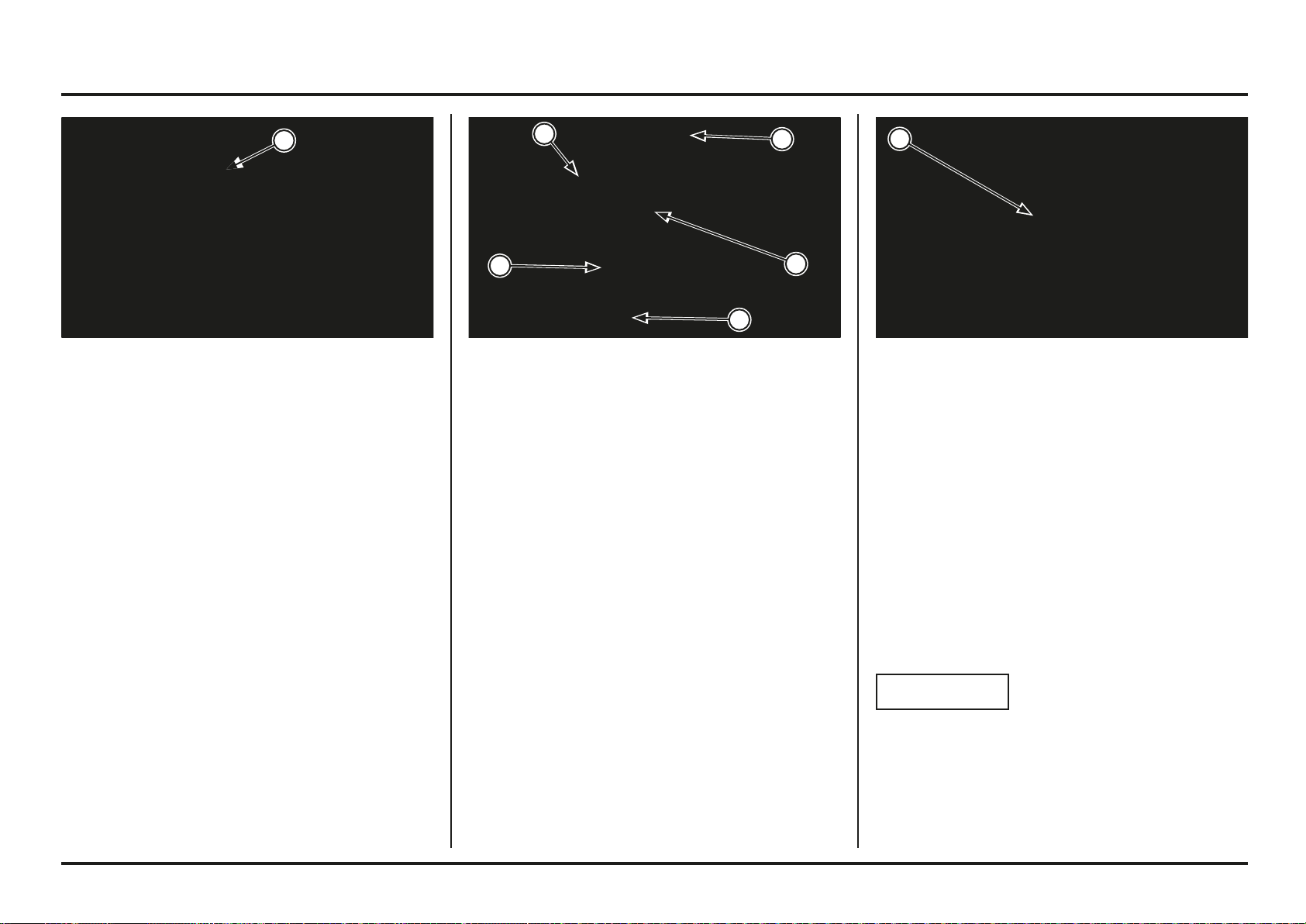
6-15
6-15
Electrical servicing
Checks:
Check for loose or defective contacts in the connectors
6P and 3P of the speedometer.
When starting the engine, check that the speedometer
light comes on.
If the speedometer does not work at first, check the
power lines and ground for the speedometer.
If the speedometer works initially but later does not move
when in motion, check the system for the speed sensor.
Checking the power/ground lines
– Remove the speedometer.
NOTICE
Do not disconnect the connector 6P on the speedometer
during the checks.
With the connector 6P of the speedometer connected,
check the following in the connector on the harness side.
(1) SPEEDOMETER(1) HOUSING FOR THE UPPER HEADLIGHT
(2) BOLTS
(3) SPEEDOMETER
(4) CONNECTOR 6P
(5) CONNECTOR 3P
Speedometer
– Remove the housing for the upper headlight.
– Remove the screws and the speedometer
– Disconnect the connectors 6P (white) and 3P (white)
from the speedometer.
Carry out the installation in the reverse order to removal.
TORQUE:
2 Pinch bolts for the speedometer: 1.0 N•m (0.1 kgf•m)
(1) CONNECTOR 2P FROM THE REAR BRAKE LIGHT
SWITCH.
Rear:
Disconnect the connector 2P from the rear brake light
switch.
There should be continuity with the brake pedal applied,
and there should be none when this pedal is not applied.
1
5
4
3
2
1
1
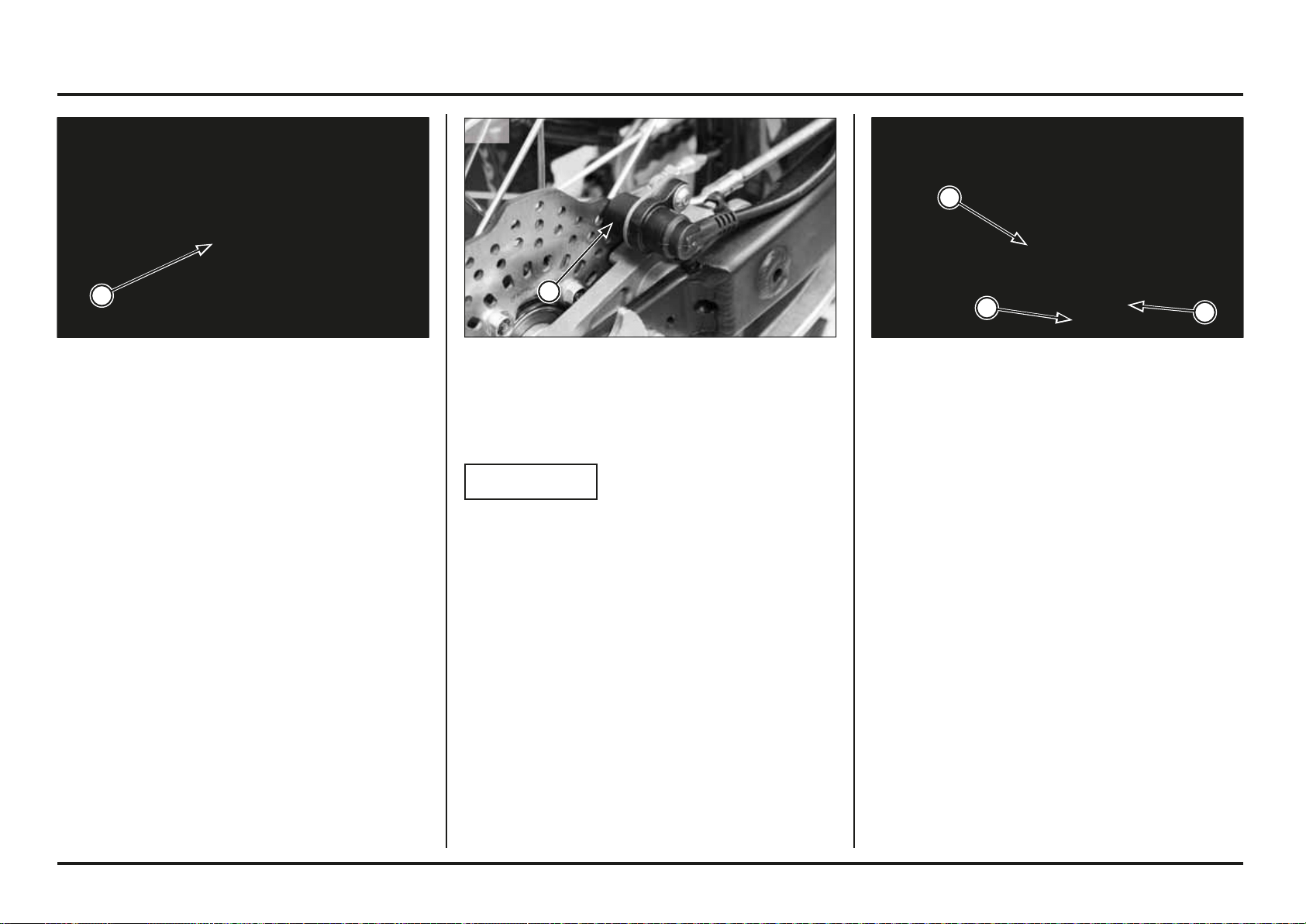
6-16
6-16
Electrical servicing
Speed sensor (2ED)
System check
NOTICE
Before starting this inspection, check the inspection of
the speedometer system.
Checking the air gap
Safely support the motorcycle with a lifting device or
equivalent and raise the wheel off the ground.
Measure the gap (air gap) between the sensor and the
brake disc at different points by turning the wheel slowly.
It must be within the specification.
Standard: 0.5 – 1.5 mm (0.031 – 0.035 in)
The air gap cannot be adjusted.
If it is not within the specification, check whether there
are deformities, damage or if any of the parts assembled
are loose.
(1) SPEED SENSOR(1) CONNECTOR 6P
Power input line
Measure the voltage between the connector 6P of the
speedometer and the ground.
Connection: White/Red(+) – Ground (–)
With the engine on, around 12V should be received.
If there is no voltage, check the existence of an open
circuit in the White/Red wire.
Ground line
Measure the continuity between the connector 6P of the
speedometer and the ground.
Connection: Green – Ground
There must be continuity at all times.
If there is no continuity, check the existence of an open
circuit in the green wire.
(1) HOUSING FOR THE UPPER HEADLIGHT
(2) CONNECTOR 6P
(3) CONNECTOR 3P
Checking the speed sensor
Remove the housing for the upper headlight.
Check if there are loose or defective contacts in the
connector 3P (white) of the speed sensor.
Connect the connector 3P (white) of the speed sensor.
Start the engine.
Measure the voltage between the terminals of the
connector 3P (white) of the speed sensor on the wire
side.
Connection: Red (+) and Black (–)
Standard: 5V.
If the standard voltage appears, replace the speed sensor.
If there is no standard voltage, check the following:
The blue wire in case there is an open circuit.
The red wire in case there is an open circuit.
Speedometer.
1
1
3
2
1
2ED
2ED
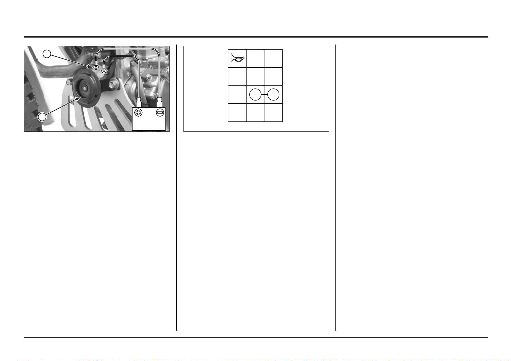
6-17
6-17
Electrical servicing
If there is no voltage, check the following:
Open circuit in the Black wire between the ignition
relay and the connector 9P (white) on the handlebar.
If there is voltage, check the continuity between the
terminals in each switch position, as shown in the table.
Disconnect the horn’s connectors.
Connect the 12 V battery to the horn’s terminals.
The horn is working properly when it makes a noise when
the 12 V battery is connected to its terminals.
Horn (2ED)
Checks:
If the engine starts but the horn does not work, check the
following:
Loose connection.
Start the engine and check the voltage between the
following terminals of the connector 9P (white) on the
harness side:
Connection: Black (+) and Ground (–)
Standard: 12V approximately.
(1) HORN
(2) CONNECTORS
G
FREE
PUSH
COLOR
LG
Ho
GND
INTERRUPTOR DE LA BOCINA
BATERÍABATERÍA
HORN SWITCH
BATTERY
2
1
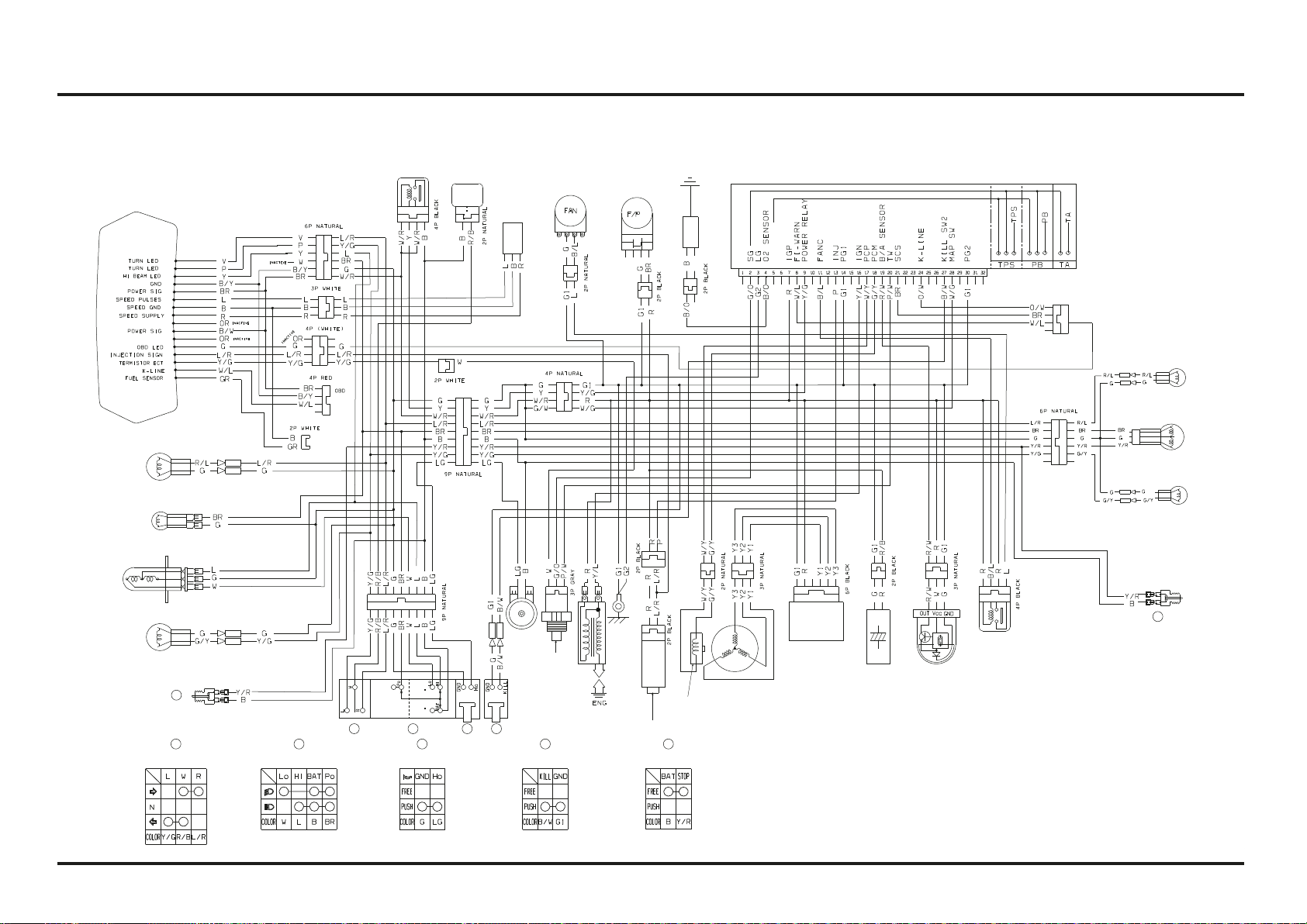
6-18
6-18
Electrical servicing
Wiring diagram (2ED)
3
2
5
4
1
3
2 5
4
1
5
DIGITAL METER 2V
RIGHT FRONT TURN
SIGNAL LIGHT
12V 10 W
POSITION LIGHT
12V 4W
HEADLIGHT
12V 35/35W
LEFT FRONT TURN
SIGNAL LIGHT
12V 10W
FRONT BRAKE
LIGHT SWITCH
BRAKE LIGHT SWITCHTURN SIGNAL SWITCH LIGHTING SWITCH HORN SWITCH STOP SWITCH
HORN
WATER
TEMP
SENSOR
IGNITION COIL
PULSER
ALTERNATOR
REGULATOR/
RECTIFIER
CONDENSER
(10000uF)
BANK ANGLE
SENSOR
FAN RELAY
POWER
RELAY
WINKER
RELAY
0
2
SENSOR
F1 - ECU
SPEED
SENSOR
FAN
MOTOR
FUEL
PUMP
SERVICE
CHECK
CONNECTOR
RIGHT REAR
TURN SIGNAL LIGHT
12V 10W
LEFT REAR
TURN SIGNAL LIGHT
12V 10W
REAR BRAKE
LIGHT SWITCH
BRAKE, TAILLIGHT,
LICENSE PLATE PLATE LIGHT
12V 21/5W
POWER
INJECTOR
B BLACK
Y YELLOW
L BLUE
G GREEN
R RED
W WHITE
V VIOLET
BR BROWN
O ORANGE
SB LIGHT BLUE
LG LIGHT GREEN
P PINK
GR GREY
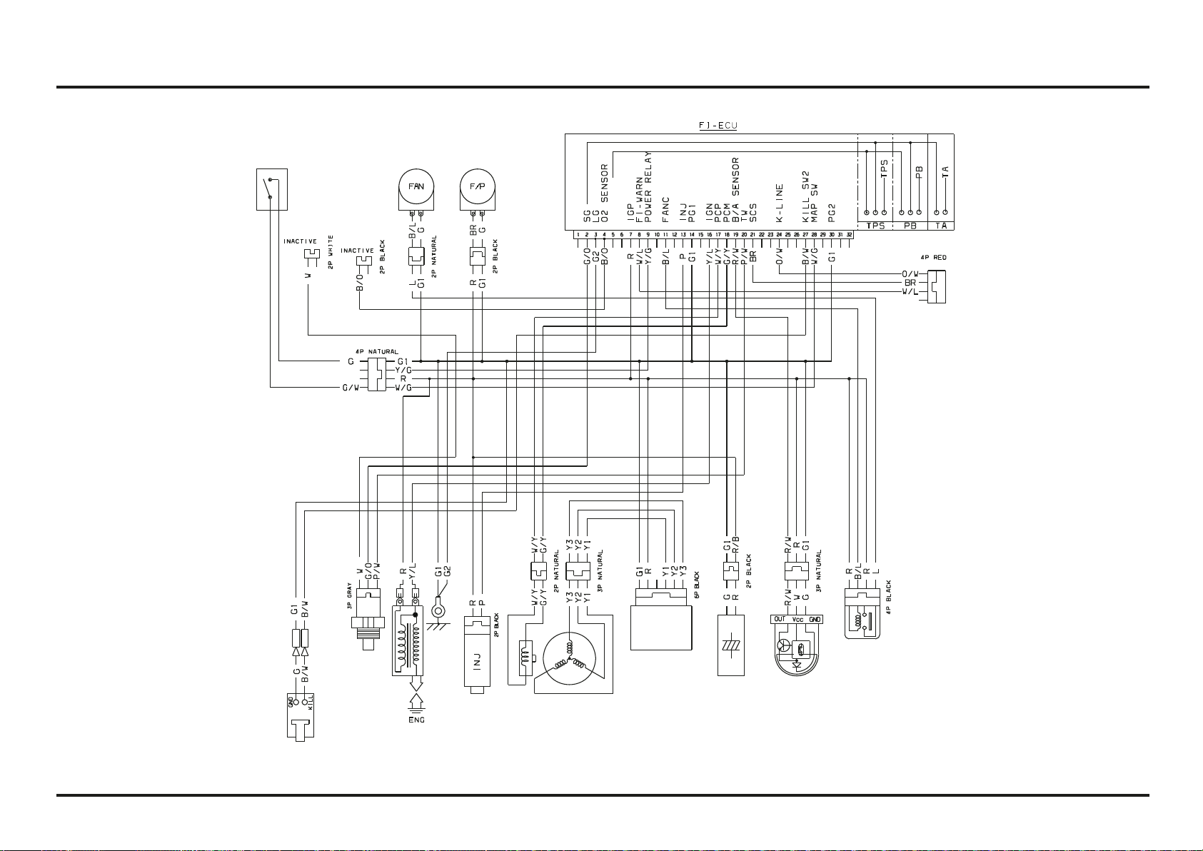
6-19
6-19
Electrical servicing
Wiring diagram (4ED)
SERVICE
CHECK
CONNECTOR
POWER
WATER
TEMP
SENSOR
IGNITION COIL
FUN RELAY
PULSER
ALTERNADOR
REGULATOR/RECTIFIER
CONDENSER
(10000uF)
BANK ANGLE
SENSOR
FAN
MOTOR
FUEL
PUMP
MAPPING
SWITCH
B BLACK
Y YELLOW
L BLUE
G GREEN
R RED
W WHITE
V VIOLET
BR BROWN
O ORANGE
SB LIGHT BLUE
LG LIGHT GREEN
P PINK
GR GREY
ENGINE
STOP
SWITCH