
Contents
Contents
These pages give an overview of the contents of your owner’s
manual.
The first page of each section lists the topics covered in that section.
ATV Safety ..................................................................................1
Important safety information you should know, plus a look at the
safety related labels on your ATV.
Instruments & Controls ..............................................................9
The location and function of indicators and controls on your ATV
and operating instructions for various controls and features.
Before Riding ............................................................................57
The importance of wearing a helmet and other protective gear,
how to make sure you and your ATV are ready to ride, and
important information about loading.
Basic Operation & Riding .........................................................73
How to start and stop the engine, shift gears, and brake. Also,
riding precautions.
Contents
31HR4660
2020 Foreman (TRX520FM1 4x4/FM2 4x4 with Power Steering)
MOM 17110 (1903)

Contents
Contents
Servicing Your Honda ............................................................107
Why your ATV needs regular maintenance, what you need to
know before servicing your Honda, an owner maintenance
schedule, and instructions for specific maintenance and
adjustment items.
Tips ..........................................................................................201
How to store and transport your ATV and how to be an
environmentally responsible rider.
Taking Care of the Unexpected.............................................211
What to do if you have a flat tire, your engine won’t start, etc.
Technical Information ............................................................233
ID numbers, technical specifications, and other technical facts.
Consumer Information...........................................................249
Information on warranties, emission controls, how to get Honda
service manuals.
Index........................................................................................256
Quick Reference
Handy facts about fuel, engine oil, tire sizes, and air pressures.
FOR OFF-ROAD USE ONLY
This vehicle is designed and manufactured for off-road use only.
USA only:
It conforms to US EPA Noise Emission regulations, but does not
conform to Federal Motor Vehicle Safety Standards or US EPA On
Highway Exhaust Emission regulations, and operation on public
streets, roads, or highways is illegal. The vehicle is equipped with a
USDA qualified spark arrester. Obey local laws and regulations.
It conforms to US EPA, California, and Environment Climate Change
Canada emission regulations for ATVs.
2020
Honda
TRX520FM1 4x4
TRX520FM2 4x4 with Power Steering
FOURTRAX FOREMAN
OWNER’S MANUAL

ATV Safety
1
ATV Safety
A T V S a fe ty
This section presents some of the most important information and
recommendations to help you ride your ATV safely. Please take a few
moments to read these pages. This section also includes information
about the location of safety labels on your ATV.
Important Safety Information........................................................ 2
Safety Labels ................................................................................ 5

ATV Safety
2
Important Safety Information
Your ATV can provide many years of service and pleasure if you take
responsibility for your own safety and understand the challenges you
can meet while riding.
There is much that you can do to protect yourself when you ride.
You’ll find many helpful recommendations throughout this manual.
The following are a few that we consider to be most important.
Follow the Age Recommendation
The minimum recommended age for this ATV model is 16. Children
under age 16 should never operate this vehicle. Refer to the age
warnings provided in this manual and on the ATV.
Always Wear a Helmet
It’s a proven fact: helmets significantly reduce the number and
severity of head injuries. So always wear an approved motorcycle
helmet. We also recommend that you wear eye protection, sturdy
boots, gloves, and other protective gear (page 58).
Never Carry a Passenger
Your ATV is designed for one person only. There are no handholds,
footrests, or seat for a second person, so never carry a passenger. A
passenger could interfere with your ability to move around to
maintain your balance and control of the ATV.

ATV Safety
7
Safety Labels
Improper tire pressure or overloading can
cause loss of control.
Loss of control can result in severe injury
or death.
Cold tire pressure :
Maximum weight capacity : 551lbs. (250kg)
Front : 4.4psi (30kPa)
Rear : 4.4psi (30kPa)
Overloading this ATV or carrying cargo
improperly can change handling, stability
and braking performance and can lead to an
accident.
Never exceed the maximum front cargo limit
of : 88 lbs (40 kg).
Refer to instructions in the Owner’s
Manual.
WARNING

ATV Safety
8
Safety Labels
(For Canada)
NEVER ride as a passenger.
Passengers can cause a loss
of control, resulting in
SEVERE INJURY or DEATH.
With four-wheel drive, operating any brake control
causes braking at both the front and rear wheels.
For detailed braking information, refer to the
Owner's Manual.
BRAKING INFORMATION
Operating this ATV if you are under
the age of 16 increases your chance
of severe injury or death.
NEVER operate this ATV if you are
under age 16.
WARNING
Improper ATV use can result in SEVERE INJURY or DEATH
without proper training or instruction
at speeds too fast for your skills or the conditions
on public roads - a collision can occur with
another vehicle
with a passenger - passengers affect balance
and steering and increase risk of losing control
ALWAYS:
use proper riding techniques to avoid vehicle
overturns on hills and rough terrain and in turns
avoid paved surfaces - pavement may seriously
affect handling and control
LOCATE AND READ OWNER'S MANUAL.
FOLLOW ALL INSTRUCTIONS AND WARNINGS.
NEVER operate:
ALWAYS USE
AN APPROVED
HELMET AND
PROTECTIVE
GEAR
NEVER USE NEVER USE
ON PUBLIC
ROADS
NEVER CARRY
PASSENGERS
WITH DRUGS
OR ALCOHOL
Overloading this ATV or carrying cargo
improperly can change handling, stability
and braking performance and can lead to an
accident.
Never exceed the maximum rear cargo limit
(combined weight on the rear rack and in
the storage area) of : 176 lbs (80 kg).
Refer to instructions in the Owner’s
Manual.
WARNING
Towing an improperly loaded
trailer can cause loss of control.
Read towing instructions
in owner's manual
Tow weight limit : 850lbs. (385kg)
: 30lbs. ( 14kg)
Tongue weight
Driving in Front Differential Lock Mode changes the
way your vehicle handles and turns. Use this mode only
at low speed. See owner’s manual for more information.
DRIVELINE INFORMATION

Instruments & Controls
9
Instruments & Controls
(cont’d)
Instruments & Controls
This section shows the location of all indicators and controls you
would normally use before or while riding your ATV.
The items listed on this page are described in this section.
Instructions for other components are presented in other sections of
this manual where they will be most useful.
Operation Component Locations ................................................ 11
Indicators & Displays................................................................... 14
Multi-function Display.............................................................. 20
Speed and Mileage Unit Changing........................................... 22
4WD Indicator ......................................................................... 22
Gear Position Indicator............................................................. 23
Fuel Gauge.............................................................................. 24
Digital Clock............................................................................ 26
Odometer................................................................................ 27
Tripmeter................................................................................. 27
Coolant Temperature Gauge ................................................... 28
Hour meter.............................................................................. 30
Maintenance Tripmeter/Maintenance Hour meter.................... 31

Instruments & Controls
11
Operation Component Locations
headlight dimmer switch
P/R lever
rear brake lever/
parking brake lever
engine stop switch
start/override button
ignition switch
differential lock
switch
throttle lever
front brake lever
headlight switch
4WD switch
Instruments & Controls
12
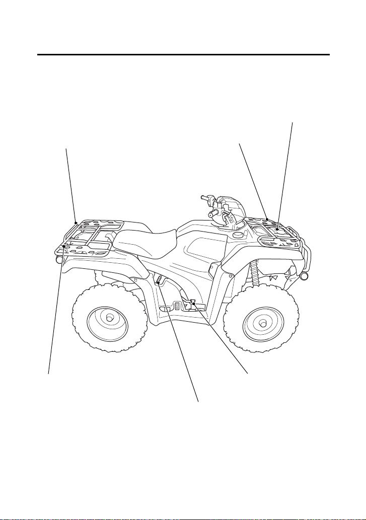
Operation Component Locations
rear cargo rack
front cargo rack
rear brake pedal
recoil starter
(Canada only)
flag pole bracket
front utility box
Instruments & Controls
13
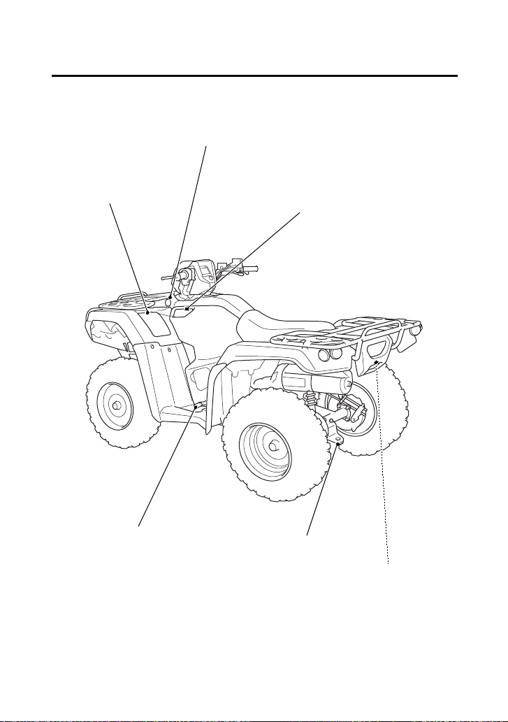
Operation Component Locations
trailer hitch
shift lever
storage compartment
accessory socket
side utility box
utility pocket

Instruments & Controls
18
Indicators & Displays
7 Multi-function
display
The display includes the following
functions. Display Check.
4WD indicator Shows when the 4WD drive mode is
engaged. If the indicator blinks with
the differential lock indicator when
there is any abnormality in the front
final gear system. See page 38.
Gear position
indicator
Shows the gear position (page 23).
Maintenance
minder indicator
Shows when specified maintenance
interval is reached (page 32).
Speedometer Shows riding speed.
Fuel gauge Shows approximate fuel supply
available (page 24).
Digital clock Shows the time (hours and minutes)
(page 26).
Odometer Shows accumulated mileage
(page 27).
Tripmeter Shows mileage per trip (page 27).
Coolant
temperature
gauge
Shows approximate coolant
temperature (page 28).
Hour meter Shows hours and tenths of hours of
engine operation (page 30).
Maintenance
tripmeter
Inform when the mileage or operating
hours on your ATV approaches and
passes the interval specified on the
maintenance schedule (page 31).
Maintenance hour
meter

Instruments & Controls
23
Indicators & Displays
The gear position indicator (1) shows the gear position when the
ignition switch is in the ON (q) position.
The indicator displays: N for neutral, R for reverse, and 1 – 5 for the
five forward gears.
“–” will be displayed on the gear position indicator when the
transmission is not shifted into gear properly. Before riding, check
that the gear position is properly displayed on the gear position
indicator.
If the gear position indicator shows “–” or blinks, turn the ignition
switch to the OFF (w) position, and then turn it back to the ON (q)
position again.
If the gear position indicator shows “–”, rock the vehicle back and
forth and make sure the gear position indicator is displayed properly
and then if the gear position indicator still shows “–” or blinks, see
your dealer.
If the “–” on the gear position indicator is blinking, see your dealer.
Gear Position Indicator
(1)
(1) gear position indicator

Instruments & Controls
29
Indicators & Displays
When the coolant is over specified temperature, the 5th segment (6)
appears and the high coolant temperature indicator (7) lights.
If this occurs, stop the engine and check the reserve tank coolant level.
Read pages 221 – 222 and do not ride the ATV until the problem has
been corrected.
NOTICE
Continuing to ride with an overheated engine can cause serious
engine damage.
If the “C – – – – – H” (8) blinks, the meter input signal fails. See your
dealer.
(6) (7)
(7) high coolant
temperature indicator
(6) 5th segment
(8) “C – – – – – H”
(8)

Instruments & Controls
30
Indicators & Displays
The hour meter (1) shows accumulated hours while the ignition
switch is ON (q) with the hour meter mark (2). The hour meter
provides accurate service period information for initial and regular
maintenance. The hour meter locks at 99,999.9 when the readout
exceeds 99,999.9.
Hour meter
(1) (2)
(1) hour meter (2) hour meter mark
Instruments & Controls
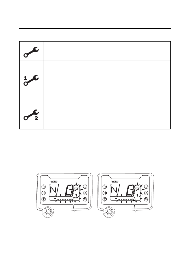
32
Indicators & Displays
Maintenance Minder Indicators:
When the maintenance tripmeter or maintenance hour meter
amounts to 0, the display of the maintenance minder indicator
changes. When selected the maintenance tripmeter or maintenance
hour meter, the maintenance minder indicator and lower part of the
multi-function display (4) start blinking. When selected other mode,
the maintenance minder indicator appears in the display.
Initial Maintenance
Appears at 100 miles (150 km) or 20 operating hours,
whichever comes first.
Regular Maintenance Interval 1
Appears 600 miles (1,000 km) or 100 operating
hours after the Initial Maintenance or Regular
Maintenance Interval 2 is performed and
maintenance minder is reset, whichever comes first in
the maintenance schedule.
Regular Maintenance Interval 2
Appears 600 miles (1,000 km) or 100 operating
hours after Regular Maintenance Interval 1 is
performed and maintenance minder is reset,
whichever comes first in the maintenance schedule.
(4) (4)
(4) lower part of the multi-function display
Instruments & Controls
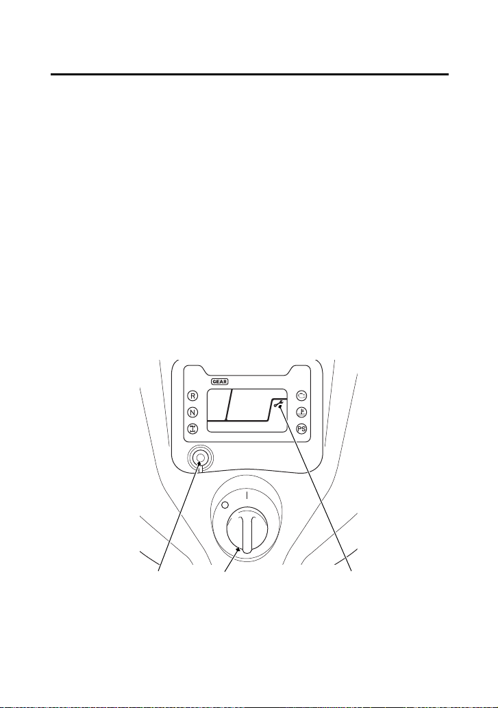
33
Indicators & Displays
Reset the maintenance tripmeter/maintenance hour meter after
maintenances.
To reset the maintenance tripmeter/maintenance hour meter,
proceed as follows:
Press and hold the mode select button (5) and turn the ignition
switch (6) to ON (q). The maintenance minder indicator will appear,
then it will blinks twice, and the multi-function display will
temporarily show all the modes and digital segments. The indicator
message will disappear.
Reset operation will be cancelled, if the mode select button is
released before the indicator blinks twice.
If the maintenance is done before the setting interval, be sure to
reset the meters after the maintenance.
(5) mode select button(2) maintenance minder
indicator
(6) ignition switch
(5) (6) (2)

Instruments & Controls
35
Controls & Features
Your ATV is equipped with a 4WD switch (1), which permits a choice
between the “2WD” and “4WD” drive modes. Select a drive mode
that’s suitable for your riding.
Keep both hands on the handlebar while machine is in motion and
come to a complete stop before using the 4WD switch.
The 4WD switch is located above the throttle lever. To select the
drive mode, with your ATV stopped, push the 4WD switch.
To check your present drive mode, look at the 4WD indicator (2).
2WD mode: the 4WD indicator disappears when the 2WD mode engages.
4WD mode: the 4WD indicator appears when the 4WD mode engages.
If the 4WD indicator does not appear when selecting the 4WD
mode, accelerate your ATV slowly until the 4WD indicator appears.
The 4WD indicator and differential lock indicator both flash together
when there is any abnormality in the front final gear system. See
Front Differential Lock and Speed Limiter Override (Differential Lock
Switch and Start/Override Button) page 38.
4WD Switch
(2)
(1)
(1) 4WD switch (2) 4WD indicator
4WD mode
2WD mode
4WD mode
2WD mode
(1)

Instruments & Controls
36
Controls & Features
Your ATV is equipped with a front differential lock feature that
includes a speed limiter and speed limiter override. This system is
designed to provide maximum traction to help you escape from
situations where the vehicle might otherwise become stuck, in the
mud for example. When the front differential lock mode is activated,
the front differential gear is locked causing all four wheels to rotate
at the same speed. Because locking all four wheels together changes
the way the vehicle handles and increases the amount of room
necessary to turn, a speed limiter restricts the speed to 20 mph (32
km/h). Pushing and holding the start/override button in this mode
allows you to momentarily override the 20 mph (32 km/h) speed
limiter, up to 40 mph (64 km/h), to help you free the vehicle in more
severe conditions. You should only use this feature where maximum
traction is required and only in low speeds. For normal riding, use
2WD and 4WD modes.
Front Differential Lock and Speed Limiter Override
(Differential Lock Switch and Start/Override Button)

Instruments & Controls
39
Controls & Features
The start/override button (1) is used for starting the engine and
activate the speed limiter override mode.
Pushing the button in starts the engine. See Starting Procedure,
page 82.
When the engine is not running and the start/override button is
pushed, the starter motor will crank the engine. The starter motor
will not operate if the engine stop switch is in the OFF (r) position
when the start/override button is pushed.
To activate the speed limiter override mode, see Front Differential
Lock and Speed Limiter Override (Differential Lock Switch and Start/
Override Button), page 36.
Start/Override Button
LEFT HANDLEBAR
(1)
(1) start/override button
START or SPEED LIMITER OVERRIDE MODE

Instruments & Controls
40
Controls & Features
The engine stop switch (1) is used to stop the engine in an
emergency. To operate, slide the switch to the OFF (r) position. The
switch must be in the RUN (e) position to start the engine, and it
should normally remain in the RUN (e) position even when the
engine is OFF.
If your ATV is stopped with the ignition switch ON (q) and the engine
stop switch OFF (r), the battery will discharge. Turn the ignition
switch to OFF (w) to prevent battery discharge.
Engine Stop Switch
e r
LEFT HANDLEBAR
(1)
(1) engine stop switch r OFF
e RUN
Instruments & Controls
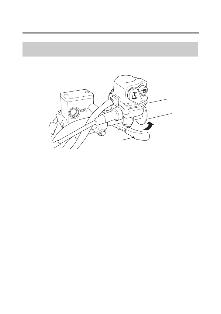
43
Controls & Features
The throttle controls engine rpm (speed). To increase engine rpm,
press the throttle lever (1) with your thumb. To reduce engine rpm,
release pressure on the throttle lever. The throttle will automatically
return to the closed position (engine idle) when you remove your
thumb.
Throttle Lever
RIGHT HANDLEBAR
(A)
(1) throttle lever
(1)
(A) to open the throttle

Instruments & Controls
47
Controls & Features
Flag poles are optional equipment available from your dealer. To
mount a pole in the bracket (1), follow the instructions that come
with the flag pole kit.
Flag poles are required in some riding areas. Check local regulations
before riding.
Flag Pole Bracket
RIGHT REAR
(1) flag pole bracket
(1)

Instruments & Controls
50
Controls & Features
Be sure the engine is on and the headlights are turned off before
using the accessory socket, otherwise you may drain the battery.
The accessory socket’s rated capacity is DC 12 V, 120 Watts (10 A)
or less. If you exceed this limit, you may blow a fuse. See If a Fuse
Blows, page 223.
When you are done using an accessory, unplug it, and cover the
socket with the cap.
Be careful not to flood this accessory socket when washing your
ATV.

Instruments & Controls
52
Controls & Features
The front utility box (1) is located on the front center cover. You may
store small, lightweight items in the box.
To open:
Pull up the front of the front utility box cover (2).
To close:
Push down the front of the front utility box cover until it locks in
place. Make sure that the studs (3) are locked securely in position by
pulling up lightly on the front of the front utility box cover.
Do not store valuable items in the front utility box.
Be careful not to flood this area when washing your ATV.
Front Utility Box
FRONT CENTER COVER
(1) front utility box
(3)
(2) front utility box cover
(1)
(3) studs
(2)

Instruments & Controls
56
BLANK PAGE

Before Riding
58
Are You Ready to Ride?
Before you ride your ATV for the first time, we urge you to:
• Read this owner’s manual and the labels on your ATV carefully.
• Make sure you understand all the safety messages.
• Know how to operate all the controls.
Before each ride, be sure:
• You feel well and are in good physical and mental condition.
• You are wearing an approved motorcycle helmet (with chin strap
tightened securely), eye protection, and other protective
clothing.
• You don’t have any alcohol or drugs in your system.
For your safety, we strongly recommend that you always wear an
approved motorcycle helmet, eye protection, boots, gloves, long
pants, and a long-sleeved shirt or jacket whenever you ride.
Although complete protection is not possible, wearing proper gear
can reduce the chance of injury when you ride.
Following are suggestions to help you choose the proper gear.
Helmet and Eye Protection
Your helmet is your most important piece of riding gear because it
offers the best protection against head injuries. A helmet should fit
your head comfortably and securely.
Protective Apparel

Before Riding
65
Is Your ATV Ready to Ride?
(cont’d)
If you are carrying cargo, also check the following:
Check these items after you get on the ATV:
Cable Check the cable housings for wear. Check
the fittings for looseness. Replace or tighten
as needed.
Lights Make sure the headlights, brake light and
taillight are working properly.
Loading Limits Make sure you do not exceed the load limits
(page 68).
Cargo Check that all cargo is secure.
Throttle Check the freeplay and adjust if needed.
Press the throttle to make sure it moves
smoothly without sticking, and snaps shut
automatically when it is released, in all
steering positions (page 157).
Brakes Squeeze the front and rear brake levers and
step on the rear brake pedal to check that
the controls operate normally. Check for
proper freeplay (pages 173, 175). Make sure
there is no brake fluid leakage.
Reverse Assist Lever Check the freeplay and adjust if needed
(page 160). Make sure the lever operates
smoothly without sticking.

Before Riding
66
Is Your ATV Ready to Ride?
Remember, be sure to take care of any problem you find, or have
your dealer correct it before you ride.
Headlight and
Headlight Dimmer
Switch
Check for proper function (page 41).
Engine Stop Switch Check for proper function (page 40).
Steering Check that the wheels turn properly as you
steer the handlebar. Move the handlebar
right and left and check that there is no
excessive backlash.

Before Riding
68
Load Limits & Guidelines
Following are the load limits for your ATV:
There are limits to how much weight can be carried on your ATV and
be pulled in a trailer.
The following load limits apply to standard equipment only.
Modifying your ATV, using non-standard equipment, or riding on
terrain that is not flat and smooth could further reduce these limits.
Tongue weight can be measured with an ordinary bathroom scale.
Place the scale under the tongue, using either a tongue jack or other
support to keep the trailer level.
The weight of added accessories will reduce the maximum cargo
weight you can carry.
Load Limits
maximum weight capacity 551 lb (250 kg)
(includes the weight of the rider,
all cargo, and accessories.)
front cargo rack weight limit
rear cargo rack weight limit
tow weight limit
= 88 lb (40 kg)
= 176 lb (80 kg)
= 850 lb (385 kg)
(Combined weight of the trailer
and all cargo in the trailer)
tongue weight = 30 lb (14 kg) recommended
(Weight on the trailer tongue)
tongue and rear cargo weight = 176 lb (80 kg) maximum
(Combined weight on the
trailer tongue and on the rear
cargo rack)

Before Riding
72
BLANK PAGE

Basic Operation & Riding
73
Basic Operation & Riding
(cont’d)
Basic Operation & Riding
This section gives basic riding instructions, including how to start and
stop your engine, and how to use the throttle and brakes. It also
provides important information on riding with cargo.
To protect your new engine and enjoy optimum performance and
service life, refer to Break-in Guidelines (page 241).
Safe Riding Precautions .............................................................. 75
Off-road Use Only.................................................................... 75
Keep Hands and Feet on Controls............................................ 76
Control Speed ......................................................................... 77
Use Care on Unfamiliar or Rough Terrain................................. 78
Do Not Perform Stunts............................................................. 79
Starting & Stopping the Engine................................................... 80
Preparation.............................................................................. 81
Starting Procedure................................................................... 82
Flooded Engine........................................................................ 83
Bank Angle Sensor Ignition Cut-off System.............................. 83
Stalled Engine.......................................................................... 84
How to Stop the Engine........................................................... 85
Using the Recoil Starter (Canada only) ..................................... 86
Shifting Gears............................................................................. 87
Riding in Reverse........................................................................ 89

Basic Operation & Riding
74
Basic Operation & Riding
Braking....................................................................................... 91
Riding Your ATV......................................................................... 93
Making Turns .......................................................................... 93
Skidding or Sliding................................................................... 95
Riding Up Hills ......................................................................... 96
Riding Down Hills .................................................................. 100
Crossing or Turning on Hills or Slopes.................................... 101
Riding Over Obstacles............................................................ 103
Riding Through Water ........................................................... 104
Parking..................................................................................... 106

Basic Operation & Riding
75
Safe Riding Precautions
Before riding your ATV for the first time, please review the ATV
Safety section beginning on page 1, and the Before Riding section
beginning on page 57.
Even if you have ridden other ATVs, take time to become familiar
with how this ATV works and handles. Practice in a safe area until
you build your skills and get accustomed to the ATV’s size and
weight.
Your ATV and its tires are designed and manufactured for off-road
use only, not for pavement. Riding on pavement can affect handling
and control. You should not ride your ATV on pavement.
When riding off-road, also remember to always obey local off-road
riding laws and regulations. Obtain permission to ride on private
property. Avoid posted areas and obey “no trespassing” signs.
Off-road Use Only
WARNING
3
WARNING
Operating this ATV on paved surfaces may
seriously affect handling and control of the
ATV, and may cause the vehicle to go out of
control.
Never operate the ATV on any paved surfaces,
including sidewalks, driveways, parking lots
and streets.

Basic Operation & Riding
76
Safe Riding Precautions
You should never ride your ATV on public streets, roads or highways,
even if they are not paved. Drivers of street vehicles may have difficulty
seeing and avoiding you, which could lead to a collision. In many states
it is illegal to operate ATVs on public streets, roads and highways.
Always keep both hands on the handlebars and both feet on the footpegs
when riding your ATV. This is important to maintain your balance and to
control the vehicle. Removing even one hand from the handlebars or one
foot from the footpegs can reduce your ability to control the ATV or could
cause you to lose your balance and fall off the ATV.
WARNING
3
WARNING
Operating this ATV on public streets, roads or
highways could cause you to collide with
another vehicle.
Never operate this ATV on any public street,
road or highway, even a dirt or gravel one.
Keep Hands and Feet on Controls
WARNING
3
WARNING
Removing hands from handlebars or feet
from footpegs during operation can reduce
your ability to control the ATV or could cause
you to lose your balance and fall off of the
ATV.
Always keep both hands on the handlebars
and both feet on the footpegs of your ATV
during operation.

Basic Operation & Riding
78
Safe Riding Precautions
Before riding in a new area, always check the terrain thoroughly.
Don’t ride fast on unfamiliar terrain or when visibility is limited. (It’s
sometimes difficult to see obstructions like hidden rocks, bumps, or
holes in time to react.)
Use Care on Unfamiliar or Rough Terrain
WARNING
3
WARNING
Failure to use extra care when operating this
ATV on unfamiliar terrain could result in the
ATV overturning or going out of control.
Go slowly and be extra careful when
operating on unfamiliar terrain. Always be
alert to changing terrain conditions when
operating the ATV.

Basic Operation & Riding
82
Starting & Stopping the Engine
This ATV is fuel-injected with an automatic choke.
Follow the procedure indicated below.
Any Air Temperature
• Press the start/override button with the throttle completely
closed.
The engine will not start if the throttle is fully open (because the
electronic control module cuts off the fuel supply).
Snapping the throttle or fast idling for more than 5 minutes may
cause exhaust pipe and muffler discolorations.
Starting Procedure

Basic Operation & Riding
84
Starting & Stopping the Engine
You can restart the engine while the vehicle is stopped by squeezing
the front brake lever and pressing the start/override button.
Do not press the throttle lever while starting in gear. The engine will
not start if the throttle is fully open (because the electronic control
module cuts off the fuel supply).
Once you have started the engine, release the front brake lever, then
apply throttle gradually.
Stalled Engine

Basic Operation & Riding
88
Shifting Gears
2.
With the throttle closed, raise the shift lever one full stroke to
shift into 1st (first) gear.
3.
Release the rear brake lever/parking brake lever and increase
engine speed by gradually opening the throttle.
4.
When speed increases, release the throttle and shift to 2nd gear
by raising the shift lever one full stroke.
5.
Repeat this sequence to progressively upshift to 3rd, 4th and 5th
(top) gear.
6.
To downshift, reverse this sequence. Remember to close the
throttle each time you shift to the next lower gear.
Learning when to shift gears comes with experience. Keep the
following tips in mind:
• As a general rule, shift while moving in a straight line.
• Close the throttle completely before shifting. Improper shifting
may damage the engine, transmission, and drivetrain.
• Upshift to a higher gear or reduce throttle before engine rpm
(speed) gets too high. Learn the relationship between engine
sound and the normal shifting points.
• Downshift to a lower gear before you feel the engine laboring
(lugging) at low rpm.
• Avoid downshifting to help slow your ATV when engine rpm is
high. Downshifting when engine speed is near its allowable
maximum may over-rev the engine and possibly cause damage.
• To prevent transmission damage, do not coast or tow the ATV for
long distances with the engine off.
Recommended Shift Points
Ride in the highest gear that lets the engine run and accelerate
smoothly.
This will give you good fuel economy and effective emissions control.

Basic Operation & Riding
89
Riding in Reverse
If you need to ride in reverse, make sure the area behind you is clear
and only operate the ATV at low speed.
1.
Bring the vehicle to a complete stop, then make sure the
transmission is in neutral.
2.
Be sure there are no obstacles or people in the way.
3.
Fully rotate the P/R lever (1) counterclockwise to engage the P/R
lever with the reverse assist lever (2).
4.
While continuing to hold the P/R lever, squeeze the rear brake
lever/parking brake lever (3), then depress the shift lever once to
shift into “R” (reverse) gear.
WARNING
3
WARNING
Improperly operating in reverse could cause
you to hit an obstacle or person behind you,
resulting in serious injury.
Make sure there are no obstacles or people
behind you before selecting reverse gear.
When it is safe to proceed, go slowly.
LEFT HANDLEBAR
(2) reverse assist lever
(3)
(3) rear brake lever/parking brake lever
(1)
(2)
(1) P/R lever

Basic Operation & Riding
90
Riding in Reverse
NOTICE
Your ATV may be equipped with a reverse speed limiter, which helps
the vehicle to maintain a safe speed while riding in reverse gear.
5.
Make sure that the reverse indicator comes on and the gear
position indicator shows “R”.
6.
Release the rear brake lever/parking brake lever.
7.
Open the throttle gradually and ride slowly. Do not open the
throttle suddenly or make abrupt turns.
8.
To stop, close the throttle and gradually apply both the front and
rear brakes. Do not abruptly apply the rear brake by alone.
9.
To shift out of reverse and into neutral, raise the shift lever one
stroke to shift into “N” (neutral) gear.
WARNING
3
WARNING
Applying only the rear brake abruptly when
operating in reverse gear could cause the
front wheels to lift off the ground and the
ATV could overturn backwards.
Carefully apply both the front and rear brakes
when stopping in reverse gear.
Basic Operation & Riding
94
Riding Your ATV
To make a turn on level ground: Steer the handlebar and lean your
body toward the inside of the turn. Leaning helps balance the
vehicle, and it feels more comfortable. Leaning into a turn is an
important technique to master in riding an ATV.
To make a sharp turn at low speed: It helps to shift your body slightly
forward on the seat, and lean inside, as you steer the handlebar.
Shifting weight forward allows the rear wheels to turn easier, and it
also improves front-wheel steering.
To make a turn from a full stop: Apply the throttle gradually when
you turn and start at the same time. Remember to shift your body
forward to make sharp low-speed turns and whenever you turn
while accelerating from a full stop.
Lean your body to the inside of a turn and forward.

Basic Operation & Riding
95
Riding Your ATV
The terrain surface can be a major factor affecting turns. Skidding
during a turn is more likely to occur on slippery surfaces, such as
snow, ice, mud and loose gravel. If you skid on ice, you may lose all
directional control. To avoid skidding on slippery terrain, keep your
speed low and ride with caution.
If your ATV skids sideways during a turn, steer in the direction of the
skid. Avoid hard braking or accelerating until you have regained
directional control.
Remember that steering the handlebar in the front differential lock
mode will cause steering to be heavy and increase turning radius.
Skidding or Sliding
WARNING
3
WARNING
Skidding or sliding improperly may cause you
to lose control of this ATV. You may also
regain traction unexpectedly, which may
cause the ATV to overturn.
Learn to safely control skidding by practicing
at low speeds and on level, smooth terrain.
Basic Operation & Riding
97
Riding Your ATV
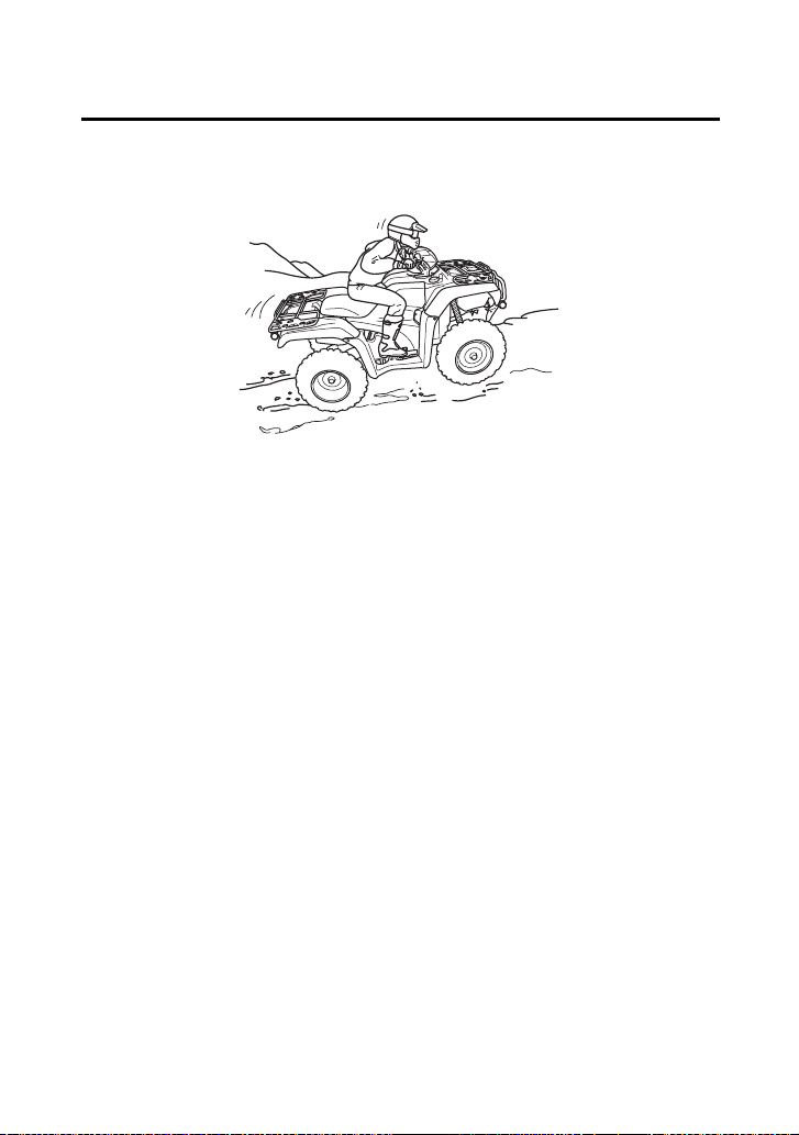
• Always check the terrain carefully before you start up any hill.
• Never climb hills with excessively slippery or loose surfaces.
• To climb a hill, take a running start in an appropriate gear and
speed for the conditions. Maintain a steady speed as you ascend
the hill.
• Never open the throttle suddenly or make sudden gear changes.
The ATV could flip over backward.
• Never go over the top of any hill at high speed. An obstacle, a
sharp drop, or another vehicle or person could be on the other
side of the hill.
Shift weight forward when climbing hills.

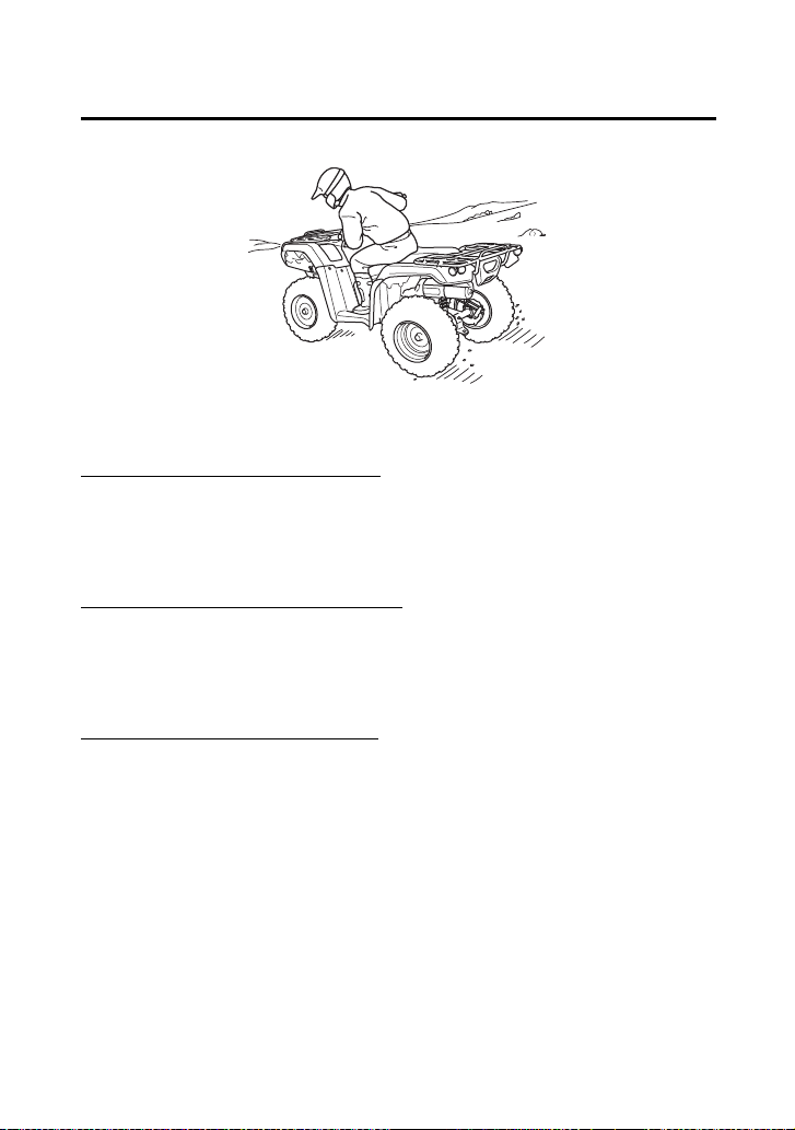
Basic Operation & Riding
98
Riding Your ATV
Stalling the ATV and/or Rolling Backwards:
If you incorrectly estimate climbing capability or terrain conditions,
the ATV may not have enough power or traction to continue uphill.
If this happens, the ATV can stall and/or roll backwards.
What to do if the ATV stalls or rolls backwards when climbing a hill:
If you are about to lose all forward speed:
1.
Using the front and rear brakes together, bring the ATV to a stop
with the vehicle pointed straight uphill.
2.
Get off the ATV while you continue holding the brakes.
3.
Shift into neutral, set the parking brake and turn the engine off.
4.
Then assess the situation.
If the ATV starts rolling backwards before you begin braking:
1.
Keep your weight uphill.
2.
Carefully apply the front brakes first, then carefully apply the rear
brake. Do not apply either brake abruptly if you are rolling
backwards, or the vehicle may overturn.
If the ATV continues sliding backwards:
After you’ve applied the brakes, get off and away from the vehicle.
Remember that operating any brake control in the 4WD mode will
cause braking at both the front and rear wheels.
WARNING
3
WARNING
Stalling, rolling backwards or improperly
dismounting while climbing a hill could result
in the ATV overturning.
Always follow proper procedures for climbing
a hill as described in this owner’s manual.
Basic Operation & Riding
102
Riding Your ATV
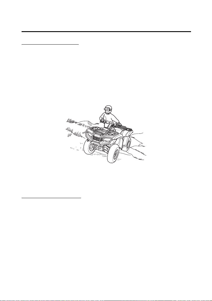
Crossing Hills or Slopes
• To maintain balance and stability when riding across a slope, you
need to shift weight toward the uphill side of the vehicle. To do
this, move your body off the center of the seat and lean toward
the uphill side.
• On a slippery or loose surface, you may also need to steer slightly
uphill to maintain a straight course across the slope.
• Avoid crossing hills that are excessively steep, slippery or rough.
Making Turns on Slopes
• Compared to riding on level ground, you may need to shift more
weight and lean more when making turns on slopes.
• Do not make turns on any slopes until you have first mastered the
techniques for making turns on level terrain.
Shift weight uphill when crossing slopes.

Basic Operation & Riding
103
Riding Your ATV
Before operating in a new area, check for obstacles. Watch out for
bumps, rain ruts, potholes and other obstacles in the terrain. When
you approach any obstacle, reduce your speed and be prepared to
stop.
Never try to ride over large obstacles, such as large rocks or fallen
logs.
Riding Over Obstacles
WARNING
3
WARNING
Improperly operating over obstacles could
cause loss of control or a collision and could
cause the ATV to overturn.
When you go over obstacles, always follow
proper procedures as described in this
owner’s manual.

Basic Operation & Riding
104
Riding Your ATV
Your ATV is designed to travel through water up to approximately
10 inches (254 mm) deep. Before crossing a stream, make sure the
water is not too deep or flowing too fast.
NOTICE
Water entering the muffler may damage the oxygen sensor and
result in emissions control system malfunction. Have your ATV dealer
inspect the oxygen sensor immediately after water enters the
muffler.
Riding Through Water
WARNING
3
WARNING
The ATV tires have some ability to float.
Operating this ATV through deep or fast-
flowing water may cause a loss of traction
and loss of control, which could lead to a
crash.
Never operate this ATV in fast-flowing water
or in water deeper than that specified in this
owner’s manual.

Servicing Your Honda
108
Servicing Your Honda
Clip Removal ............................................................................ 125
Service Procedures
Fluids & Filters
Fuel.......................................................................................... 126
Engine Oil & Filter..................................................................... 129
Rear Final Gear Oil.................................................................... 138
Front Final Gear Oil................................................................... 141
Coolant.................................................................................... 143
Air Cleaner............................................................................... 151
Engine
Throttle .................................................................................... 157
Clutch System .......................................................................... 159
Reverse Inhibitor System ........................................................... 160
Spark Plug................................................................................ 161
Valves....................................................................................... 164
Spark Arrester .......................................................................... 165
Chassis
Suspension............................................................................... 166
Brakes ...................................................................................... 169
Tires ......................................................................................... 180
Guards ..................................................................................... 187
Drivetrain Boots........................................................................ 189
Electrical
Battery ..................................................................................... 191
Appearance Care...................................................................... 196

Servicing Your Honda
109
B efor e You Serv ice Your H onda
The Importance of Maintenance
A well-maintained ATV is essential for safe, economical, and trouble-
free riding. It will also help reduce air pollution. Careful pre-ride
inspections and good maintenance are especially important because
your ATV is designed to be ridden over rough off-road terrain.
To help you properly care for your ATV, this section of the manual
provides a Maintenance Schedule. The service intervals in this
schedule are based on average riding conditions.
Frequent servicing of the air cleaner is especially important to help
you avoid a possible costly engine repair.
If your ATV overturns or is involved in a crash, be sure your dealer
inspects all major parts, even if you are able to make some repairs.
WARNING
3
WARNING
Improperly maintaining this ATV or failing to
correct a problem before you ride can cause a
crash in which you can be seriously hurt or
killed.
Always follow the inspection and
maintenance recommendations and
schedules in this owner’s manual.

Servicing Your Honda
110
Maintenance Safety
This section includes instructions on how to perform some important
maintenance tasks. If you have basic mechanical skills, you can
perform many of these tasks with the tools provided with your ATV.
Other tasks that are more difficult and require special tools are best
performed by professionals. Removing the wheels should normally
be handled only by a Honda technician or other qualified mechanic.
Instructions are included in this manual only to assist in emergency
service.
Some of the most important safety precautions follow. However, we
cannot warn you of every conceivable hazard that can arise in
performing maintenance. Only you can decide whether or not you
should perform a given task.
WARNING
3
WARNING
Failure to properly follow maintenance
instructions and precautions can cause you to
be seriously hurt or killed.
Always follow the procedures and
precautions in this owner’s manual.

Servicing Your Honda
112
Maintenance Schedule
The required Maintenance Schedule that follows specifies how often
you should have your ATV serviced, and what things need attention.
It is essential to have your ATV serviced as scheduled to maintain
safe, dependable performance and proper emission control.
The service intervals in this Maintenance Schedule are based on
average riding conditions. Some items will need more frequent
service if you ride in unusually wet or dusty areas or at full throttle.
Consult your dealer for recommendations applicable to your
individual needs and use.
Some items in the Maintenance Schedule can be performed with
basic mechanical skills and hand tools. Procedures for these items
are provided in this manual. Other items involve more extensive
procedures and may require special training, tools, and equipment.
We recommend that you have your dealer perform these tasks
unless you have advanced mechanical skills and the required tools
and equipment. Procedures for such items in this schedule are
provided in an official Honda Service Manual available for purchase
(page 250).
If you do not feel capable of performing a given task or need
assistance, remember that your Honda dealer knows your ATV best
and is fully equipped to maintain and repair it. If you decide to do
your own maintenance, use only Honda Genuine Parts or their
equivalents for repair or replacement to ensure the best quality and
reliability.

Servicing Your Honda
113
Maintenance Schedule
Perform the pre-ride inspection (page 63) and owner maintenance
on this section at each scheduled maintenance period.
Each item on the maintenance schedule requires some mechanical
knowledge. Certain items (particularly those marked
*
and
**
) may
require more technical information and tools. Consult your dealer.
Summary of Maintenance Schedule Notes & Procedures:
NOTES:
1.
Service more frequently when riding in dusty areas, sand or
snow.
2.
Service more frequently after riding in very wet or muddy
conditions.
3.
Replace every 2 years. Replacement requires mechanical skill.
4.
California type only
* Should be serviced by your dealer, unless the owner has proper
tools and service data and is mechanically qualified. Refer to the
official Honda Service Manual (page 250).
** In the interest of safety, we recommend these items be serviced
only by your dealer.

Servicing Your Honda
114
Maintenance Schedule
Maintenance Procedures:
I: inspect and clean, adjust, lubricate, or replace, if necessary
C: clean
A: adjust
L: lubricate
R: replace
* Should be serviced by your dealer, unless the owner has proper tools and service data and is
mechanically qualified. Refer to the official Honda Service Manual (page 250).
FREQUENCY
WHICHEVER
COMES FIRST
INITIAL REGULAR
Refer to
page
MAINT. MAINT. INTERVAL
mi 100 600 1200
km 150 1000 2000
MONTH
1612
ITEMS NOTE HOURS 20 100 200
* FUEL LINE I —
* THROTTLE OPERATION I 157
AIR CLEANER
NOTE 1
C C 151
AIR CLEANER HOUSING
DRAIN TUBE
NOTE 2
I I 156
SPARK PLUG I I 161
* VALVE CLEARANCE I I I 164
ENGINE OIL INITIAL=
100 mi (150 km), 20
operating hours or 1
month: R
129
ENGINE OIL FILTER REGULAR=
Every 600 mi (1,000 km),
100 operating hours or 12
months: R
134
* ENGINE IDLE SPEED I I I —
* EVAPORATIVE EMISSION
CONTROL SYSTEM (For AC
type)
NOTE 4
I: EVERY 2 YEARS
—
RADIATOR COOLANT
NOTE 3
I I 143
* COOLING SYSTEM
NOTE 2
II—

Servicing Your Honda
116
Maintenance Record
Keeping an accurate maintenance record will help ensure that your
ATV is properly maintained. Retain detailed receipts to verify the
maintenance was performed. If the ATV is sold, these receipts should
be transferred with the ATV to the new owner. Make sure whoever
performs the maintenance completes this record. All scheduled
maintenance, including the 100 mile (150 km) or 1 month or 20
hours initial maintenance, is considered a normal owner operating
cost and will be charged for by your dealer. Use the space under
Notes to record anything you want to remind yourself about or
mention to your dealer.
Miles (km) or
months or hours
ODO or
HOUR
Date Performed
By:
Notes
100 (150) or
1 or 20
600 (1,000) or
6 or 100
1,200 (2,000) or
12 or 200
1,800 (3,000) or
18 or 300
2,400 (4,000) or
24 or 400
3,000 (5,000) or
30 or 500
3,600 (6,000) or
36 or 600
4,200 (7,000) or
42 or 700
4,800 (8,000) or
48 or 800

Servicing Your Honda
120
Tool Kit
The tool kit (1) is stored under the rear fender cover (page 123).
After using the tools, be sure to use the rubber band (2) to fasten the
tool kit securely.
An optional, larger tool kit may be available. Check with your
dealer’s parts department.
UNDER REAR FENDER COVER
(1)
(2)
(1) tool kit (2) rubber band

Servicing Your Honda
122
Seat Removal
Refer to Safety Precautions on page 111.
The seat must be removed for the engine oil filter, air cleaner, spark
plug, battery and fuse maintenance and to remove the rear fender
cover and tank cover assembly, to access the owner’s manual, air
pressure gauge, tool kit, fuse puller and 40 A spare fuse.
Removal
1.
Pull the seat latch (1) at the rear of the seat.
2.
Slide the seat (2) back and lift it.
Installation
1.
Insert the front prongs (3) into the backside of the tank cover (4)
and hooks (5) on the frame, and press the studs (6) into the
grommets (7).
2.
Press down on the seat until locks.
(3) (6)
(7) (1)
(4)
(5)
(1) seat latch
(2) seat
(3) front prongs
(5) hooks
(6) studs
(7) grommets
(4) tank cover
(2)

Servicing Your Honda
124
Tank Cover Assembly Removal
Refer to Safety Precautions on page 111.
The tank cover assembly must be removed for the engine oil filter
and spark plug maintenance.
Removal
1.
Remove the seat (page 122).
2.
Carefully remove the right studs (1) and left studs from the
grommets.
3.
Remove the tank cover assembly (2) by releasing the right tabs (3)
and left tabs from the slits.
Installation
Install the tank cover assembly in the reverse order of removal.
(1) right studs
(2) tank cover assembly
(3) right tabs
(3)
(3)
(1)
(2)
(1)
Servicing Your Honda
127
Fuel
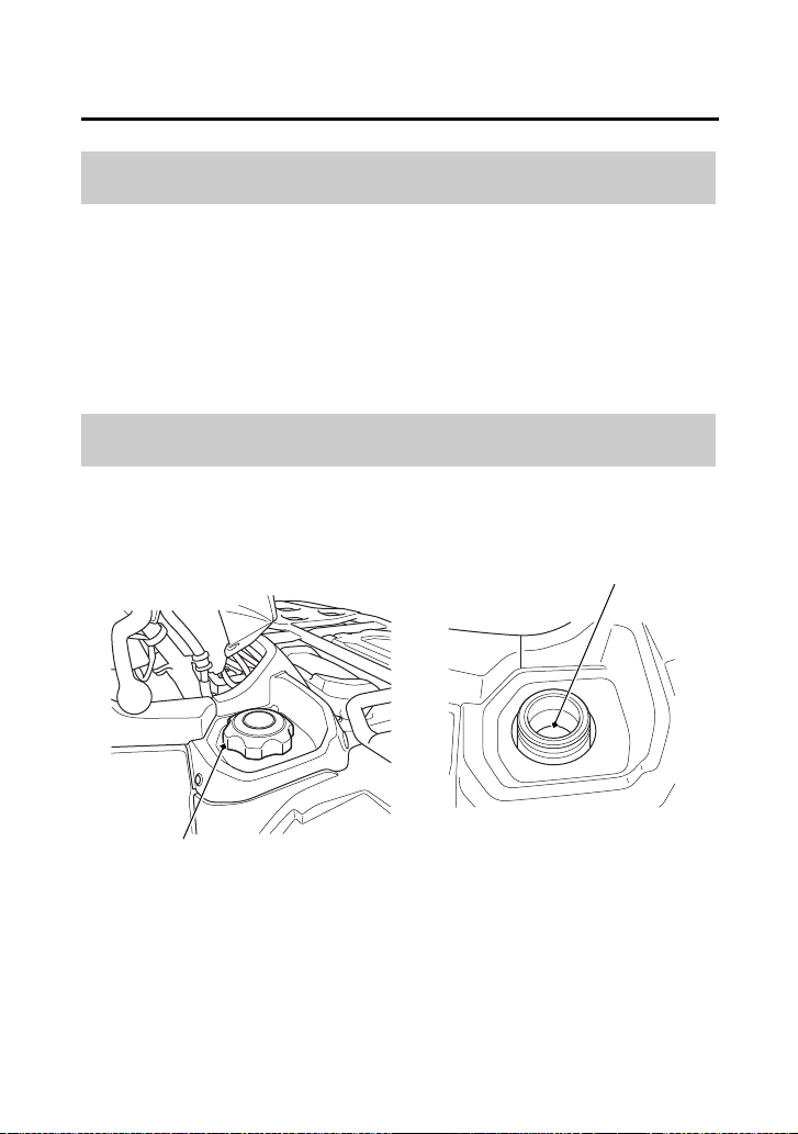
Fuel tank capacity, including reserve:
3.88 US gal (14.7 ℓ)
Reserve capacity:
1.29 US gal (4.9 ℓ)
When there is only one segment left in the fuel gauge (page 24), fuel
will be low and you should refuel as soon as possible.
Refer to Safety Precautions on page 111.
Fuel Capacity
Refueling Procedure
(1)
(2)
(1) fuel fill cap (2) bottom of the filler neck
Servicing Your Honda
132
Engine Oil & Filter
Refer to Safety Precautions on page 111.
Check the engine oil level each day before operating your ATV and
add if needed.
The oil fill cap/dipstick is located at the front left crankcase.
Before riding your ATV, check the engine oil level.
1.
Park your ATV on a firm, level surface.
2.
Start the engine in a well-ventilated area and let it idle for 3 – 5
minutes. If the air temperature is below 10°C (50°F), let the
engine idle for an additional 5 minutes (a total of 10 minutes).
3.
Stop the engine and wait 2 – 3 minutes.
4.
Remove the oil check/fill door (1) by disengaging the studs (2)
from the grommets and releasing the tabs (3) from the slits.
Checking & Adding Oil
(2)
LEFT SIDE
(1) oil check/fill door
(3)
(2) studs
(3) tabs
(1)
Servicing Your Honda
133
Engine Oil & Filter
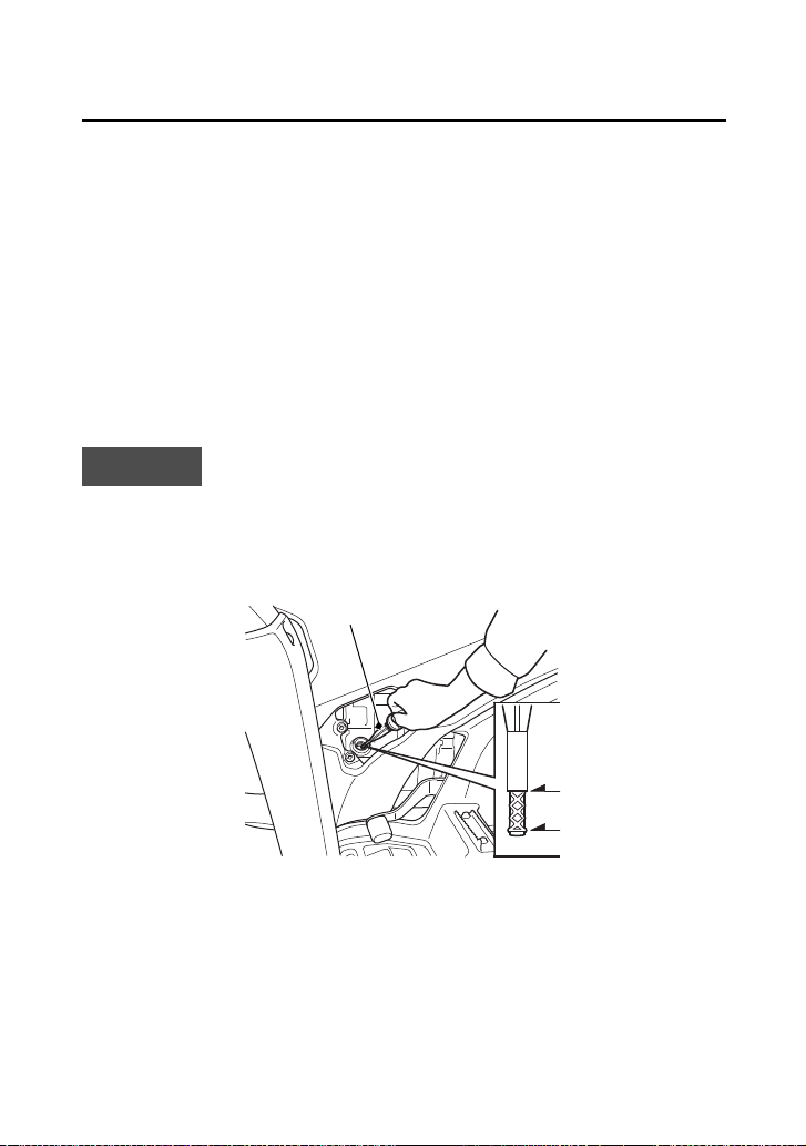
5.
Remove the oil fill cap/dipstick (4) from the front crankcase and
wipe it clean.
6.
Insert the oil fill cap/dipstick without screwing it in, then remove
the oil fill cap/dipstick and check the oil level. The oil level should
be between the upper level mark (5) and the lower level mark (6)
on the oil fill cap/dipstick.
7.
If the oil level is near or below the lower level mark, then add the
specified oil into the fill cap hole, up to the upper level mark on
the oil fill cap/dipstick. Do not overfill.
8.
Reinstall the oil fill cap/dipstick.
9.
Install the oil check/fill door.
NOTICE
Running the engine with an improper oil level can cause serious
engine damage.
LEFT SIDE
(4)
(5)
(6)
(4) oil fill cap/dipstick (5) upper level mark
(6) lower level mark

Servicing Your Honda
134
Engine Oil & Filter
Refer to Safety Precautions on page 111.
Your ATV’s oil filter has very specific performance requirements. Use
a new Honda Genuine oil filter specified for your model or a filter of
equal quality.
NOTICE
Using the wrong oil filter may result in leaks or engine damage.
This procedure requires mechanical skill and professional tools such
as a torque wrench as well as a means for disposing of the drained
fluid (page 210). If you do not have the skills or the tools, see your
dealer.
Change the oil with the engine warm to assure complete and rapid
draining.
Drain the Engine Oil:
1.
With the ATV on level ground, remove the oil check/fill door
(page 132) and the oil fill cap/dipstick from the front crankcase.
Changing Engine Oil & Filter
Servicing Your Honda
135
Engine Oil & Filter
(cont’d)
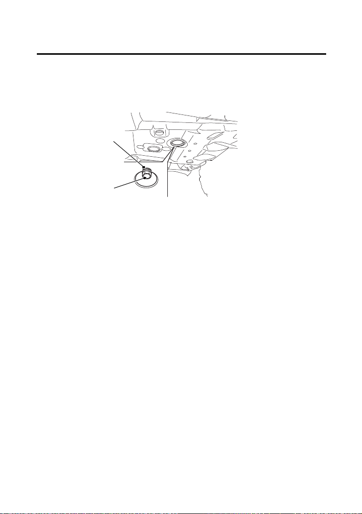
2.
Place an oil drain pan under the crankcase and remove the
engine oil drain bolt (1) and sealing washer (2).
UNDER ENGINE
(2)
(1) engine oil drain bolt
(1)
(2) sealing washer

Servicing Your Honda
137
Engine Oil & Filter
5.
Reinstall the oil filter cover, making sure the bolts are tightened
to the specified torque:
7 lbf·ft (10 N·m, 1.0 kgf·m)
6.
Pour the drained oil into a suitable container and dispose of it in
an approved manner (page 210).
NOTICE
Improper disposal of drained fluids is harmful to the environment.
7.
Install the tank cover assembly and seat.
Add Engine Oil:
1.
Reinstall the oil drain bolt with the new sealing washer and
tighten it to the specified torque:
18 lbf·ft (25 N·m, 2.5 kgf·m)
2.
Fill the crankcase with the recommended grade oil
approximately:
3.2 US qt (3.0 ℓ)
3.
Reinstall the oil fill cap/dipstick.
4.
Start the engine and let it idle for 3 – 5 minutes.
5.
Stop the engine, wait 2 – 3 minutes and check the oil level. Make
sure the oil is between the upper and lower level marks on the oil
fill cap/dipstick. If necessary, add more oil but do not overfill.
6.
Check that there are no oil leaks.
7.
Install the oil check/fill door.
If a torque wrench is not used for installation, see your dealer as
soon as possible to verify proper assembly.

Servicing Your Honda
138
Rear Final Gear Oil
Refer to Safety Precautions on page 111.
Change the oil with the rear final gear at normal operating
temperature to assure complete and rapid draining.
Oil Recommendation
type hypoid gear oil
viscosity (weight) SAE 80W-90
suggested oil Honda shaft drive oil or equivalent
Changing Oil

Servicing Your Honda
142
Front Final Gear Oil
1.
Park your ATV on a firm, level surface.
2.
Place an oil drain pan under the oil drain bolt (1).
3.
Remove the oil fill cap (2), O-ring (3), drain bolt and sealing
washer (4).
4.
After the oil has completely drained, reinstall the drain bolt with
a new sealing washer and tighten it to the specified torque:
9 lbf·ft (12 N·m, 1.2 kgf·m)
5.
Pour the drained oil into a suitable container and dispose of it in
an approved manner (page 210).
NOTICE
Improper disposal of drained fluids is harmful to the environment.
6.
Fill the front final gear case with the recommended oil.
11.0 US oz (325 cm
3
)
Make sure the oil level is at the lower edge of the oil fill inspection
hole (5).
7.
Coat a new O-ring with grease and install it into the fill cap
groove and tighten it to the specified torque:
9 lbf·ft (12 N·m, 1.2 kgf·m)
(3)
(2) oil fill cap
(4)
FRONT
(3) O-ring
(5) oil fill inspection hole
(1)
(1) oil drain bolt (4) sealing washer
(5)
(2)

Servicing Your Honda
146
Coolant
Refer to Safety Precautions on page 111.
Coolant should be replaced by your dealer, unless you have the
proper tools and service data, and are mechanically qualified. Refer
to the official Honda Service Manual (page 250).
To properly dispose of drained coolant, refer to You & the
Environment, page 210.
NOTICE
Improper disposal of drained fluids is harmful to the environment.
Coolant Replacement
WARNING
3
WARNING
Removing the radiator cap while the engine is
hot can cause the coolant to spray out,
seriously scalding you.
Always let the engine and radiator cool down
before removing the radiator cap.

Servicing Your Honda
147
Coolant
Refer to Safety Precautions on page 111.
Check the air passages for clogging or damage. Remove insects,
mud, or any obstruction with low water pressure. Have the radiator
checked by your dealer if the air flow is restricted over more than
20% of the radiator surface.
Clean the radiator core after riding the ATV in mud.
The right, left and center radiator grill covers must be removed to
clean the radiator core.
Radiator Core

Servicing Your Honda
148
Coolant
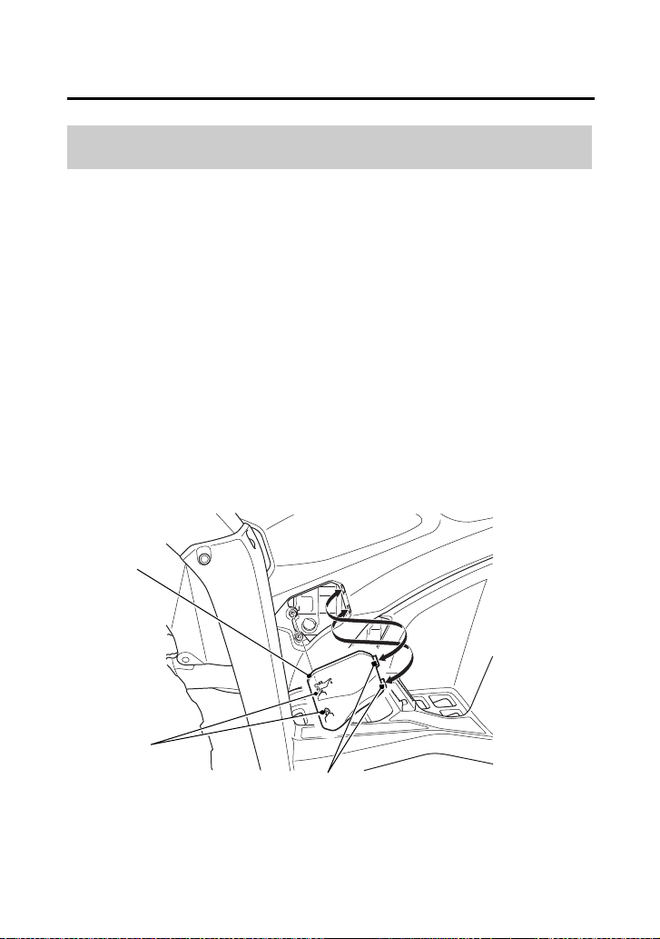
To clean the radiator core and radiator grill plate:
1.
Remove the radiator cap lid (page 145).
2.
Remove the reserve tank (1) by removing the bolt (2) and clips (3)
(page 125).
3.
Release the hoses (4) from the guides.
4.
Hold the reserve tank being careful not to spill the coolant.
LEFT FRONT
(3) clips
(4)
(3)
(1)
(2)
(3)
(1) reserve tank
(2) bolt (4) hoses
Servicing Your Honda
149
Coolant
(cont’d)
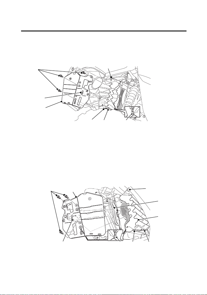
5.
Remove the clips.
6.
Remove the left radiator grill cover (5) by releasing the tab A (6),
tab B (7), tab C (8), hook A (9) and hook B (10).
7.
TRX520FM1 only:
Remove the right radiator grill cover (11) by releasing the tab A,
tab B, tab C, hook A, hook B and hose (12), then remove the
center radiator grill cover (13).
(9)
(3) clips
(8) tab C(5) left radiator grill cover
(6) tab A
(7) tab B
(9) hook A
(10) hook B
LEFT FRONT
(3)
(8)
(5)
(10)(6)(7)
RIGHT FRONT (TRX520FM1)
(10) (6) (7)
(9)(11)(3)
(12)
(8)
(11) right radiator grill cover
(12) hose
(13) center radiator grill cover
(13)

Servicing Your Honda
151
Air Cleaner
Refer to Safety Precautions on page 111.
Proper air cleaner maintenance is very important for off-road
vehicles.
A dirty, water-soaked, worn-out, or defective air cleaner will allow
dirt, dust, mud, and other impurities to pass into the engine.
Service the air cleaner more frequently if you ride in unusually wet or
dusty areas. Your dealer can help you determine the correct service
interval for your riding conditions.
Your ATV’s air cleaner has very specific performance requirements.
Use a new Honda Genuine air cleaner specified for your model or an
air cleaner of equal quality.
NOTICE
Using the wrong air cleaner may result in premature engine wear.
Proper air cleaner maintenance can prevent premature engine wear
or damage, expensive repairs, low engine power, poor gas mileage,
and spark plug fouling.
NOTICE
Improper or lack of proper air cleaner maintenance can cause poor
performance and premature engine wear.


Servicing Your Honda
155
Air Cleaner
Do not push the dust cover (1) too far into the breather joint (2).
If the dust cover is dirty, clean it.
Dust Cover
UNDER SEAT
(1)
(2)
(1) dust cover (2) breather joint

Servicing Your Honda
156
Air Cleaner
The air cleaner housing drain tube should be serviced in accordance
with the Maintenance Schedule. (Riding through water may require
more frequent inspection.) If deposits can be seen in the drain tube,
the tube must be cleaned before starting the vehicle.
1.
Remove the drain tube (1) by removing the clip (2) under the air
cleaner housing (3).
2.
Drain the deposits.
3.
Reinstall the drain tube, securing it with the clip.
Air Cleaner Housing Drain Tube
REAR
(3)
(1) drain tube (3) air cleaner housing
(2)(1)
(2) clip

Servicing Your Honda
158
Throttle
Refer to Safety Precautions on page 111.
1.
Check that the throttle assembly is positioned properly and the
securing bolts are tight.
2.
Check for smooth operation of the throttle lever from fully open
to fully closed in all steering positions. If there is a problem, see
your dealer.
3.
Inspect the condition of the throttle cable from the throttle lever
down to the throttle body. If the cable is kinked or chafed, have
it replaced.
4.
Check the throttle cable for tension or stress in all steering
positions.
5.
Lubricate the throttle cable with a commercially available cable
lubricant to prevent premature wear and corrosion.
Throttle Inspection

Servicing Your Honda
159
Clutch System
Your ATV’s shift-activated, wet, multiplate clutch is part of the
primary drive system. Proper adjustment allows a smooth, gradual
engagement when shifting gears.
Refer to Safety Precautions on page 111.
1.
Make sure the engine is cool.
2.
Make sure the ignition switch is OFF (w).
3.
Loosen the lock nut (1).
4.
Turn the clutch adjuster (2) counterclockwise until you feel slight
resistance.
5.
Turn the adjuster 1/4 turn clockwise, then tighten the lock nut to
hold the adjuster in this position.
6.
After adjustment, start the engine and test ride your ATV to be
sure the clutch is operating properly.
If you cannot get proper adjustment, or the clutch does not work
properly, the clutch friction discs may be worn. See your dealer or
refer to official Honda Service Manual (page 250).
Clutch Adjustment
LEFT FRONT
(2) (1)
(2) clutch adjuster(1) lock nut
Servicing Your Honda
160
Reverse Inhibitor System
Refer to Safety Precautions on page 111.
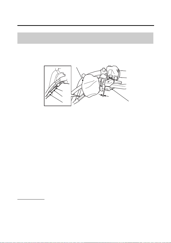
1.
Turn over the dust cover (1).
2.
Check the reverse assist lever (2) freeplay, measured at the
reverse assist lever end near the cable:
1/16 – 3/16 in (2 – 4 mm)
3.
To adjust, slide the rubber sleeve (3), loosen the lock nut (4) and
turn the adjusting nut (5) to obtain the correct freeplay.
After adjustment, tighten the lock nut securely.
4.
Return the dust cover and rubber sleeve.
Other Checks
Check the reverse assist lever and cable for loose connections or
other damage. If the cable is worn or kinked, have it replaced by
your dealer.
Reverse Inhibitor System Adjustment
LEFT HANDLEBAR
(1)
(1) dust cover
(5)
(2)
(3)
(3) rubber sleeve
(4) lock nut
(5) adjusting nut
1/16 – 3/16 in
(2 – 4 mm)
(4)
(2) reverse assist lever

Servicing Your Honda
166
Chas si s
Suspension
Your front and rear suspension systems use springs and hydraulic
damping devices that suspend your weight and most of the weight
of your ATV.
The oil damper systems hydraulically control the natural compression
and rebound of the suspension springs so that traction and comfort
are maintained as the wheels ride over rough terrain.
The spring pre-loads for your front and rear suspension systems
adjust the amount of force required to begin compression of the
spring.
Consider adjusting your suspensions pre-load whenever you change
your normal load, by adding or subtracting cargo, accessories, or
when riding conditions change.
The way you ride your ATV and the type of ride you want to
experience can also influence your suspension needs.
Lower spring pre-load provides a softer ride and is usually preferred
for light loads and smooth terrain. Higher spring pre-load provides a
firmer ride and is recommended for heavy loads and rough terrain.
Using a pin spanner, which is available from your dealer, the
suspensions can be adjusted for rider weight and riding conditions
by changing the spring pre-load.
Do not attempt to disassemble, service, or dispose of the damper;
see your dealer. The instructions found in this owner’s manual are
limited to adjustments of the shock assembly only.
Suspension Adjustment

Servicing Your Honda
168
Suspension
Position 1: for a light load and smooth terrain.
Position 2: standard position.
Positions 3 to 5: for when the ATV is more heavily loaded. (Also
increase spring pre-load for stiffer suspension.)
Make sure that both front shock absorbers are adjusted to the same
position.
Always adjust the shock absorber position in sequence (1-2-3-4-5 or
5-4-3-2-1). Attempting to adjust directly from 1 to 5 or 5 to 1 may
damage the shock absorber.

Servicing Your Honda
169
Brakes
The hydraulic disc brakes (front) and single mechanical drum brake
(rear) on your ATV dissipate heat generated by the friction of the
brake pads on the discs (front) and the brake shoes on the drum
(rear) as the wheels are slowed.
Hydraulic Disc Front Brake
As the front brake pads wear, brake fluid level will drop. A leak in the
system will also cause the level to drop.
There are no adjustments to perform, but fluid level and pad wear
must be inspected periodically. The system must be inspected
frequently to ensure there are no fluid leaks.
If the right brake lever freeplay does not feel within the normal range
while riding, check the brake pads for wear (page 172).
Worn pads should be replaced. If the pads are not worn beyond the
recommended limit, there is probably air in the brake system. See
your dealer to have the air bled from the system.
Mechanical Drum Rear Brake
If the rear brake lever/parking brake lever or brake pedal freeplay
does not feel within the normal range while riding, check the brake
shoes for wear (page 177).
The recommended brake fluid is Honda DOT 4 Brake Fluid, or any
brake fluid of equal quality and performance. Use fresh brake fluid
from a sealed container. Be sure to read the label before opening the
sealed container. An opened container may be contaminated or may
have absorbed moisture from the air.
Brake Fluid Recommendation
brake fluid Honda DOT 4 Brake Fluid

Servicing Your Honda
170
Brakes
Refer to Safety Precautions on page 111.
If your inspection indicates a low fluid level, have your dealer add the
recommended fluid.
Do not add or replace brake fluid, except in an emergency. If you do
add fluid, have your dealer check the system as soon as possible.
NOTICE
Brake fluid can damage plastic and painted surfaces. Handle with
care.
Wipe up spills immediately. Avoid brake fluid contact with skin or
eyes. If it comes in contact with your eyes, wash them out with clean
water and immediately call a doctor. If it comes in contact with your
skin, wash with clean water and, if necessary, call a doctor.
Fluid Level Inspection
Servicing Your Honda
172
Brakes
Refer to Safety Precautions on page 111.
Brake pad wear will depend upon the severity of usage and riding
conditions. The pads will wear faster in wet or muddy conditions.
Inspect the pads visually during all regular service intervals to
determine the pad wear.
Check the wear indicator (1). If the wear indicator aligns with the
edge of the reference mark (2), both pads must be replaced, see
your dealer for this replacement.
Always inspect both pads in both the right and left front brake
calipers.
Brake Pad Wear
RIGHT FRONT (Left side similar)
(1) wear indicator (2) edge of reference mark
(2)
(1)
(1)
(2)

Servicing Your Honda
173
Brakes
Inspection
Measure the distance the rear brake pedal (1) moves before the
brake starts to take hold. Freeplay, measurement at the tip of the
end of the pedal, should be:
9/16 – 13/16 in (15 – 20 mm)
If necessary, adjust to the specified range.
Rear Brake Pedal Freeplay
(1)
RIGHT SIDE
(1) rear brake pedal
9/16 – 13/16 in
(15 – 20 mm)
Servicing Your Honda
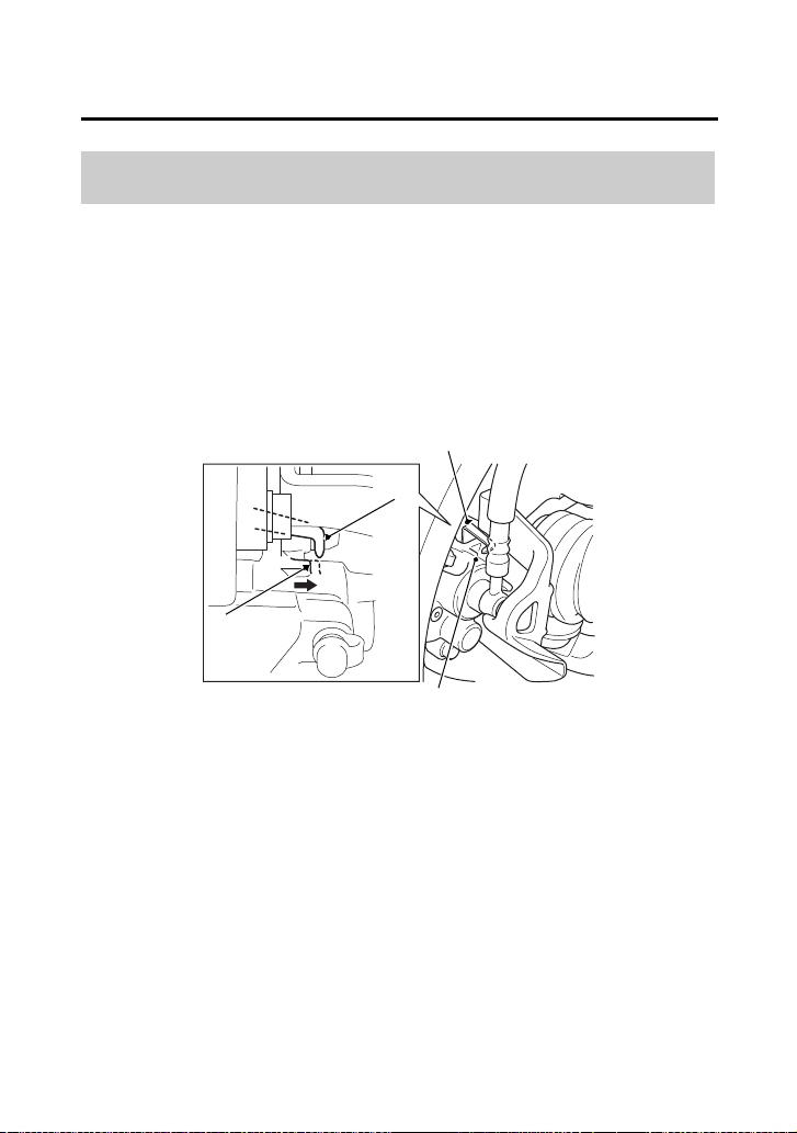
174
Brakes
Adjustment
1.
Turn the brake pedal adjusting nut (2), located on the brake
operating rod at the rear of the frame. Make sure the cutout on
the adjusting nut is properly seated on the brake arm pin (3).
2.
Adjust the freeplay of the rear brake pedal. Push the brake arm
(4), then check the clearance between the brake arm and the
brake arm pin.
(2)
RIGHT REAR
(2) brake pedal adjusting nut
(3)
(3) brake arm pin
(4)
(4) brake arm

Servicing Your Honda
176
Brakes
Adjustment
Adjust the freeplay of the rear brake lever/parking brake lever with
the front wheels pointed straight ahead.
1.
Turn the brake lever adjusting nut (2), located on the brake
operating rod at the rear of the frame. Make sure the cutout on
the adjusting nut is properly seated on the brake arm pin (3).
2.
Adjust the freeplay of the rear brake lever/parking brake lever.
Push the brake arm (4) then check the clearance between the
brake arm and the brake arm pin.
(2)
RIGHT REAR
(2) brake lever adjusting nut
(3)
(3) brake arm pin
(4)
(4) brake arm

Servicing Your Honda
177
Brakes
• Check that the rear brake lever/parking brake lever and brake
pedal assemblies are positioned properly and the securing bolts
are tight.
• Make sure that the brake cables, brake arm, spring, P/R lever, and
fasteners are in good condition.
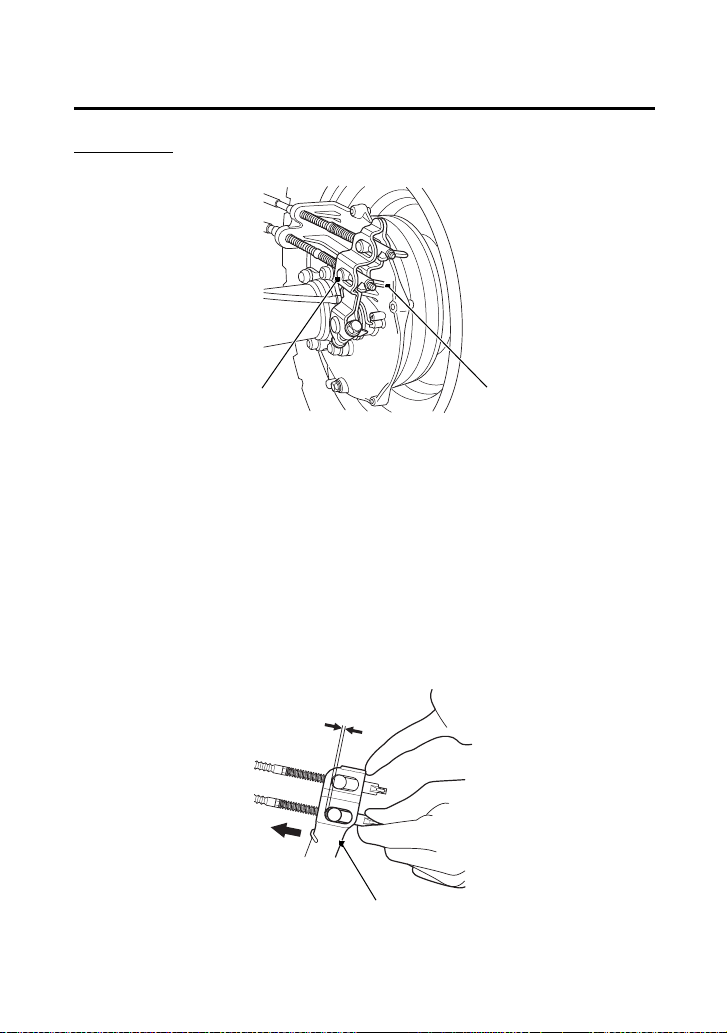
Refer to Safety Precautions on page 111.
The rear brake is equipped with an external brake wear indicator
that lets you check brake wear without disassembly. Application of
the brake control causes the arrow on the brake arm to move
toward a reference mark on the brake panel.
1.
Apply the brake control and check the movement of the arrow
(1) on the brake arm (2).
2.
Replace the brake shoe if the arrow aligns with the reference
mark (3) on the brake panel upon full application of the brake. If
replacement is necessary, see your dealer.
Other Inspections
Brake Shoe Wear
RIGHT REAR
(1) arrow
(2)
(3)
(1)
(2) brake arm
(3) reference mark

Servicing Your Honda
184
Tires
Also, if you hit a pothole or other hard object while riding, stop as
soon as you safely can and carefully inspect the tires for damage.
Tread Wear
To check the condition of a tire tread, measure the groove depth (1)
in the center of the tire, or check the wear indicator (2).
For best performance, you should replace a tire before the tread
depth at the center reaches the following limits:
front 3/16 in (4 mm)
rear 3/16 in (4 mm)
FRONT
(3)
(2)
(1)
3/16 in
(4 mm)
REAR
(1) groove depth
(2) wear indicator
(3) wear indicator
location mark
Re place
NEW
Replace
NEW
3/16 in
(4 mm)

Servicing Your Honda
185
Tires
Refer to Safety Precautions on page 111.
A tire that is repaired, either temporarily or permanently, will have
lower speed and performance limits than a new or undamaged tire.
A temporary repair can sometimes be made in an emergency
situation. However, since a temporary repair may not hold, you must
ride very slowly, preferably without any cargo, and have the tire
replaced or permanently repaired as soon as possible. (For more
information on temporary repairs, see If You Have a Flat Tire,
page 217.)
A permanent repair, such as an internal plug patch, can be made if
a tire has only a small puncture in the tread area. However you may
not be able to safely carry as much weight. If you choose to have a
tire repaired, be sure the repair work is performed by a professional.
If you have a tire professionally repaired at a non-Honda facility, we
recommend that you have the work checked by your dealer.
Tire Repair

Servicing Your Honda
187
Guards
Refer to Safety Precautions on page 111.
The engine guard (1) protects the frame, front final gear case and
engine crankcase.
The skid plate (2) protects the rear final gear case. Check the guard
and plate for cracks, damage or looseness at intervals shown in the
Maintenance Schedule.
Have the engine guard and skid plate replaced if they are cracked or
damaged. If the guard and plate bolts are loose, tighten them
securely.
Skid Plate & Engine Guard
(1)
(1) engine guard
(2)
(2) skid plate


Servicing Your Honda
191
Electr ical
Battery
Your ATV has a maintenance-free type battery. You do not have to
check the battery electrolyte level or add distilled water as you would
with a conventional-type battery.
NOTICE
Your battery is a maintenance-free type and can be permanently
damaged if the cap strip is removed.
Electrical accessories use current from the battery, even when the
ignition is OFF (w). Limited operation also allows the battery to
discharge.
If you have electrical accessories on your ATV or do not ride
frequently, we recommend that you charge the battery frequently
(see Battery Charging, page 195).
If you do not expect to ride your ATV for at least two weeks, we
recommend you remove the battery, or at least disconnect the
battery cables (negative cable first).
If you plan to store your ATV, see Battery Storage, page 192.
If your battery seems weak and/or is leaking electrolyte (causing slow
starting or other electrical problems), see your dealer.
WARNING: Battery posts, terminals and related accessories contain
lead and lead compounds. Wash your hands after handling.

Servicing Your Honda
192
Battery
Refer to Safety Precautions on page 111.
If you plan to store your ATV, we recommend you remove the
battery and store it where it can be charged at least every 30 days to
maintain its service life.
If you do not remove the battery, we recommend disconnecting the
battery cables (negative cable first).
You will get the best storage results from removing the battery and
slow charging it every 30 days (see Battery Charging, page 195).
Before you remove the battery, be sure to read all the information
that follows, as well as the information on the battery label.
Battery Storage
WARNING
3
WARNING
The battery gives off explosive hydrogen gas
during normal operation.
A spark or flame can cause the battery to
explode with enough force to kill or seriously
hurt you.
Wear protective clothing and a face shield, or
have a skilled mechanic do the battery
maintenance.

Servicing Your Honda
193
Battery
(cont’d)
The battery is located in a compartment under the rear fender cover.
Removal
1.
Make sure the ignition switch is OFF (w).
2.
Remove the seat (page 122).
3.
Remove the rear fender cover (page 123).
4.
Release the rings and remove the rubber band (1).
5.
Disconnect the negative (–) terminal lead (2) from the battery (3)
first, then disconnect the positive (+) terminal lead (4).
6.
Remove the battery taking care not to drop the terminal nuts (5).
(3)
(1) rubber band
(2) negative (–) terminal lead
(4) positive (+) terminal lead
(5) terminal nuts
UNDER REAR FENDER COVER
(2)
(4)
(1)
(3) battery
(5)

Servicing Your Honda
195
Battery
Refer to Safety Precautions on page 111.
Be sure to read the information that came with your battery charger
and follow the instructions on the battery. Improper charging may
damage the battery.
We recommend using a charger (1) designed specifically for your
Honda, which can be purchased from your dealer. These units can
be left connected for long periods without risking damage to the
battery. However, do not intentionally leave the charger connected
longer than the time period recommended in the charger’s
instructions. Avoid using an automotive-type battery charger. An
automotive charger can overheat an ATV battery and cause
premature damage.
Battery Charging
(1)
(1) charger

Servicing Your Honda
196
Appearance Care
Frequent cleaning and polishing will keep your Honda looking newer
longer.
Frequent cleaning also identifies you as an owner who values his ATV.
A clean ATV is also easier to inspect and service.
Refer to Safety Precautions on page 111.
• To clean your ATV, you may use:
– water
– Hondabrite
– a mild, neutral detergent and water
– a mild spray and wipe cleaner/polisher
– a mild spray and rinse cleaner/degreaser and water
• Avoid products that contain harsh detergents or chemical
solvents that could damage the metal, paint, plastic, and
camouflage coating on your ATV (Honda SxS).
• If your ATV is still warm from recent operation, give the engine
and exhaust system time to cool off.
• Park in a shady area. Washing your ATV in bright sunlight may
cause the finish to fade because water droplets intensify the sun’s
brightness.
• Spotting is also more likely because surface water can dry before
you have time to wipe it off.
• Clean your ATV regularly to protect surface finishes.
• We recommend the use of a low pressure garden hose to wash
your ATV. High pressure washers (like those at coin-operated car
washers) can damage certain parts of your ATV.
NOTICE
High pressure water (or air) can damage certain parts of your ATV.
Water entering the muffler may damage the oxygen sensor.
• After cleaning, inspect for damage, wear, and leaks (fuel, oil,
coolant and brake fluid).
General Recommendations

Servicing Your Honda
200
BLANK PAGE

Tips
204
Transporting Your Honda
Do not tow your ATV behind a car or other vehicle.
When you transport your ATV, we recommend that you carry the
vehicle in its normal operating position (on all four wheels). Do not
incline the vehicle upright on its rear end. This can damage the
vehicle, and leaking gasoline could be a hazard.
Follow these procedures:
1.
Set the parking brake and place the transmission in gear.

Tips
206
Storing Your Honda
If you won’t be riding for an extended period, such as during the
winter, thoroughly inspect your ATV and correct any problem before
storing it. That way, needed repairs won’t be forgotten and it will be
easier to get your ATV running again.
For more information about storage, refer to the Honda Winter
Storage Guide, available from your dealer (USA only).
We suggest you perform the following procedures to keep your ATV
in top condition. These storage procedures will reduce the
deterioration that can occur during storage.

Tips
207
Storing Your Honda
(cont’d)
Refer to Safety Precautions on page 111.
1.
Change the engine oil and filter (page 134).
2.
Make sure the cooling system is filled with a 50/50% antifreeze
solution (page 143).
3.
Fill the fuel tank. Make sure the fuel fill cap is properly installed.
4.
To prevent rusting in the cylinder, perform the following:
• Remove the spark plug cap from the spark plug (page 161).
• Remove the spark plug.
Do not connect the spark plug to the spark plug cap.
• Pour a tablespoon (15 – 20 cc) of clean engine oil into the
cylinder and cover the spark plug hole with a piece of cloth.
• With the engine stop switch in the RUN (e) position, press the
start/override button several times to crank the engine and
distribute the oil.
• Reinstall the spark plug and spark plug cap.
Preparation for Storage

Taking Care of the Unexpected
212
Taking Care of the Unexpected
Keeping your ATV well-maintained is the best way to reduce the
possibility of having a problem while riding. However, problems can
arise even with well-maintained machines.
Remember to take along your owner’s manual, the tool kit that
came with your ATV, and any other items (such as tire repair supplies
and additional tools) that might help you solve a problem on your
own.
If something goes wrong during a ride, the first thing to do is stop as
soon as you safely can. Do not continue riding if you have a flat tire,
or you hear an unusual noise, or your ATV just doesn’t feel right. If
you continue riding, you could cause more damage and endanger
your own safety.
After stopping, take time to assess the situation. Carefully inspect
your ATV to identify the problem, then consider your options before
you decide what to do.
If a problem is relatively minor and you have the tools, supplies, and
skills to make a permanent repair, you may be able to fix it on the
trail and continue riding. Or, you may be able to make a temporary
repair that allows you to slowly ride back to your base where you can
make a permanent repair or get help.
When a problem is more serious — or you don’t have the tools,
supplies, experience, or time to deal with it — you need to choose
the safest way to get yourself and your ATV back to base. For
example, if you are close enough, you (or you and another person)
might be able to push it back.
General Guidelines

Taking Care of the Unexpected
213
Taking Care of the Unexpected
Should you ever have a problem while riding, please follow these
guidelines:
• Always put personal safety first.
• Take time to assess the situation and your options before
deciding what to do.
• If the problem is relatively minor and you have the tools, supplies,
and skills to make a temporary repair, be sure to have permanent
repairs made as soon as possible.
• Do not continue riding if you are hurt or your ATV is not in safe
riding condition.
Additional recommendations for specific problems follow.

Taking Care of the Unexpected
214
If Your Engine Quits or Won’t
Start
Proper operation and maintenance can prevent starting and engine
performance problems. In many cases, the cause of the problem may
be a simple operational oversight.
If you have a problem starting the engine — or experience poor
engine performance — the following information may help you. If
you can’t correct the problem, see your dealer.
If your ATV won’t start, listen as you press the start/override button.
If you don’t hear the starter motor turning, refer to the Starter motor
doesn’t operate symptom. If you can hear the starter motor working
normally, refer to the Starter motor works, but the engine won’t
start symptom.

Taking Care of the Unexpected
219
If You Have a Flat Tire
Refer to Safety Precautions on page 111.
Removal
1.
Park your ATV on a firm, level surface.
2.
Loosen — but do not remove — the wheel nuts (1).
3.
Raise the front (or rear) wheels off the ground and place a
support block under the vehicle.
4.
Remove the wheel nuts.
5.
Remove the wheel.
• Avoid getting grease, oil, or dirt on the front brake disc or pad
surfaces when removing and installing each wheel. Any
contamination can cause poor brake performance or rapid pad
wear after reassembly.
Emergency Wheel Removal/Installation
(1)
(1)
(2)
(1) wheel nuts (2) wheel rim

Taking Care of the Unexpected
224
If a Fuse Blows
Main Fuses Access
1.
To prevent an accidental short circuit, turn the ignition switch to
OFF (w) before checking or replacing the fuses.
2.
Remove the seat (page 122).
3.
Remove the rear fender cover (page 123).
4.
To access the main fuse 1 (2), remove the fuse cover (3).
5.
To access the main fuse 2 (4), remove the fuse box cover (5).
6.
Pull the main fuse 1 out.
If the main fuse 1 is blown, install the spare fuse on the underside
of the rear fender cover (page 121).
(2) main fuse 1 (5) fuse box cover
(4)
(2)
(6) spare fuse
UNDER REAR FENDER COVER
(3)
(3) fuse cover
(4) main fuse 2
(6)
(5)
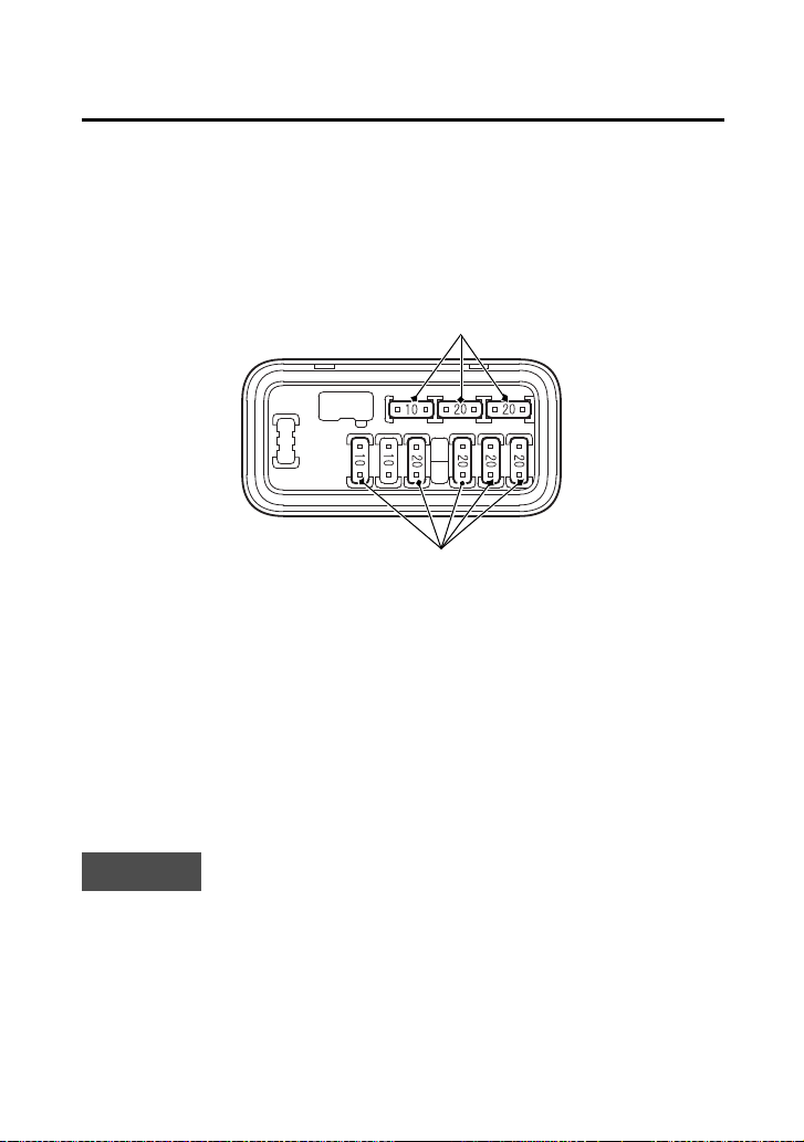
Taking Care of the Unexpected
225
If a Fuse Blows
7.
Pull the main fuse 2 out with the fuse puller on the underside of
the rear fender cover (page 121).
If the main fuse 2 is blown, install the spare fuse (6).
8.
Install the fuse cover.
Circuit Fuses Access
9.
To check or replace a circuit fuse (7), pull the old fuse out of its
retaining clips with fuse puller on the underside of the rear fender
cover (page 121).
If the fuse is blown, replace it with a spare fuse (8) of the same
rating.
If you do not have a replacement fuse with the proper rating for the
circuit, install one with a lower rating.
NOTICE
Replacing a fuse with one that has a higher rating greatly increases
the chance of damage to the electrical system.
10.
Install the fuse box cover.
11.
Install the rear fender cover.
12.
Install the seat.
(8)
(7)
(7) circuit fuses (8) spare fuses
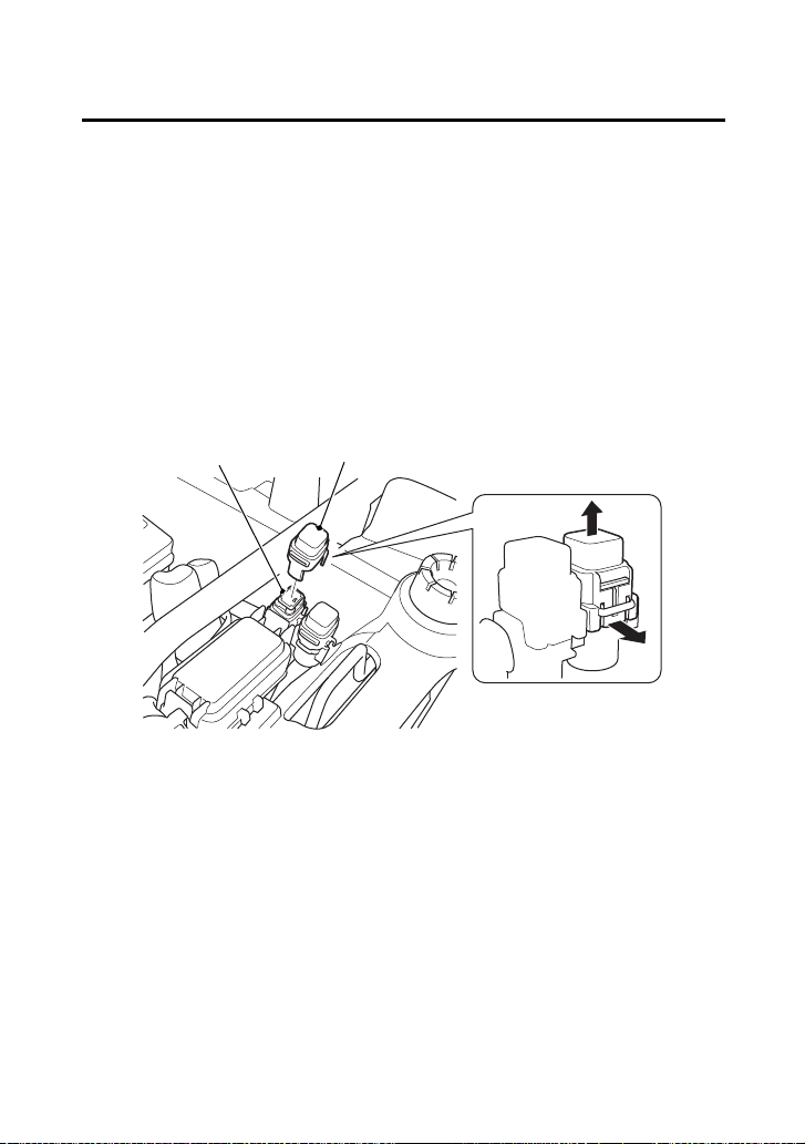
Taking Care of the Unexpected
226
If a Fuse Blows
EPS (Electric Power Steering) Fuse Access (TRX520FM2)
1.
Turn the ignition switch to OFF (w) before checking the fuse.
2.
Remove the seat (page 122).
3.
Remove the rear fender cover (page 123).
4.
To access the EPS fuse (1), remove the fuse cover (2). If the EPS
fuse is blown, see your dealer for this service.
5.
Install the fuse cover.
6.
Install the rear fender cover.
7.
Install the seat.
(1)
(1) EPS fuse (2) fuse cover
UNDER REAR FENDER COVER
(2)

Taking Care of the Unexpected
229
If You Lose Your Key
Be sure to record your key number (1). Store the spare key and
recorded key number in a safe location. You’ll need this number to
have a duplicate key made.
If you lose your key and aren’t carrying a duplicate, either get your
spare or have one made. If you don’t know your key number, call the
dealer where you purchased your Honda ATV. They may have it
listed in their records. If they don’t, transport your ATV to them or
the nearest dealer. The dealer will probably have to remove the
ignition switch assembly to find the key number so they can make a
key for you.
(1)
(1) key number

Technical Information
233
Technical Information
Technica l Information
This section contains dimensions, capacities, and other technical
data, plus information on government requirements and how to
break-in your ATV.
Vehicle Identification ................................................................ 234
Specifications ........................................................................... 236
Break-in Guidelines................................................................... 241
Emission Control Systems ......................................................... 242
Oxygenated Fuels ..................................................................... 246

Technical Information
234
Vehicle Identification
The VIN and engine serial number may be required when ordering
replacement parts. You may record these numbers in the Quick
Reference section at the rear of this manual.
The VIN (1) is stamped on the front of the frame.
Remove the radiator cap lid (page 145).
The engine number (2) is stamped on the upper side of the rear
crankcase.
Serial Numbers
FRONT
(1)
(1) VIN
REAR
(2) engine number
(2)

Technical Information
236
Specifications
Dimensions
overall length 82.9 in (2,106 mm)
overall width 47.4 in (1,205 mm)
overall height 47.8 in (1,213 mm)
wheelbase 50.0 in (1,269 mm)
ground clearance 7.5 in (190 mm)
Fuel & Lubricants
fuel
recommendation
unleaded gasoline, pump octane
number of 86 or higher
fuel tank capacity 3.88 US gal (14.7 ℓ)
including reserve
fuel tank reserve 1.29 US gal (4.9 ℓ)
engine oil
capacity
after disassembly:
3.5 US qt (3.3 ℓ)
after draining:
3.1 US qt (2.9 ℓ)
after draining & oil filter change:
3.2 US qt (3.0 ℓ)
engine oil
recommendation
API Service Classification SG or
higher except oils labeled as energy
conserving or resource conserving
on the circular API service label, SAE
10W-30, JASO T 903 standard MA,
Pro Honda GN4 4-stroke oil (USA &
Canada), or Honda 4-stroke oil, or
an equivalent motorcycle oil

Technical Information
238
Specifications
Power Transmission
primary reduction 2.103
secondary reduction 1.875
final reduction front 3.231
rear 3.154
transmission ratio 1st 4.230
2nd 2.388
3rd 1.608
4th 1.178
5th 0.848
reverse 5.743
final drive shaft
Chassis & Suspension
caster 2°
trail 0.2 in (5 mm)
tire size, front AT25 × 8-1211 MAXXIS M975
tire size, rear AT25 × 10-1211 MAXXIS M978
tire pressure,
front & rear (cold)
front:
4.4 psi (30 kPa)
rear:
4.4 psi (30 kPa)
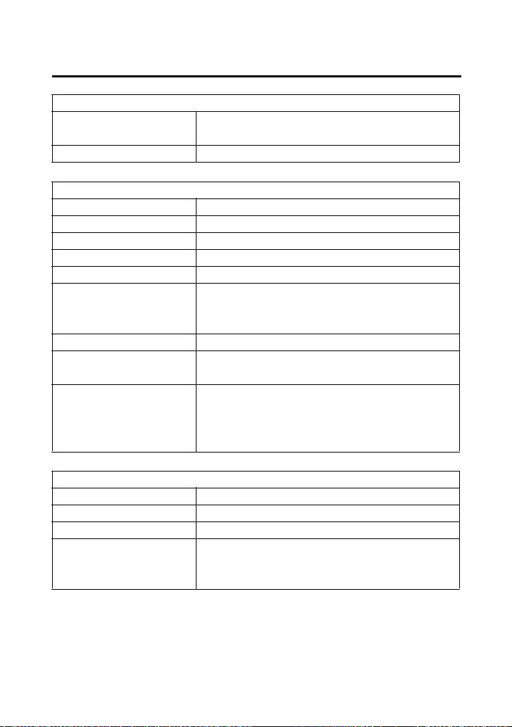
Technical Information
239
Specifications
Electrical
battery GYZ16H
12 V – 16 Ah (10HR)
generator 0.481 kW/5,000 rpm
Lights
headlight 12 V 35/35 W × 2
assist headlight 12 V 50 W
brake/tail light LED
neutral indicator LED
reverse indicator LED
high coolant
temperature
indicator
LED
PGM-FI indicator LED
differential lock
indicator
LED
PS (Electric Power
Steering)
indicator
(TRX520FM2)
LED
Fuses
main 1 40 A
main 2 10 A
other 20 A × 4, 10 A
EPS (Electric
Power Steering)
(TRX520FM2)
40 A

Technical Information
243
Emission Control Systems
Source of Exhaust Emissions
The combustion process produces carbon monoxide (CO), oxides of
nitrogen (NOx) and hydrocarbons (HC). Control of hydrocarbons and
oxides of nitrogen is very important because, under certain
conditions, they react to form photochemical smog when subjected
to sunlight. Carbon monoxide does not react in the same way, but it
is toxic.
Honda Motor Co., Ltd. utilizes various systems to reduce carbon
monoxide, oxides of nitrogen and hydrocarbons.
Exhaust Emission Control System
The exhaust emission control system includes a PGM-FI system and
oxygen sensor.
No adjustment to this system should be made although periodic
inspection of the components is recommended.
The exhaust emission control system is separate from the crankcase
emission control system.
Evaporative Emission Control System
(USA - 50 states [meets California])
An evaporative emissions control system uses a canister filled with
charcoal to adsorb fuel vapor from the fuel tank while the engine is
off. The vapor is drawn into the engine and burned while driving.
Models sold in and used in California:
An add-on or modified part must be compliant with applicable ARB
evaporative emission control standards. A violation of this
requirement is punishable by civil and/or criminal punishment.
Crankcase Emission Control System
The engine is equipped with a Closed Crankcase System to prevent
discharging crankcase vapors into the atmosphere. Blow-by gas is
returned to the combustion chamber through the air cleaner,
throttle body and intake-manifold.

Consumer Information
249
Consumer Information
Consumer I nformation
This section contains information on your warranty and how to get
an official Honda service manual.
Authorized Manuals ................................................................. 250
Warranty Coverage .................................................................. 251
Warranty Service ...................................................................... 252
Contacting Honda .................................................................... 253
Your Honda Dealer................................................................... 254

Consumer Information
250
Authorized Manuals
The Service Manual used by your authorized dealer is available from
your Honda dealer or Helm, Inc. (USA only, Canada: See your dealer
to order authorized manuals.)
Also available but not necessary to service your model is the Honda
Common Service Manual which explains theory of operation and
basic service information for various systems on Honda motorcycles,
scooters, ATVs, and SxSs.
The Winter Storage Guide in conjunction with the Owner's Manual
and Service Manual can help you prepare your Honda motorcycle,
scooter, ATV, and SxS for winter storage.
These Honda manuals are written for the professional technician,
but most mechanically capable owners should find them easy to use
if they have the proper tools and observe proper safety standards.
Special Honda tools are necessary for some procedures.
Order online: www.helminc.com
Order Toll Free: 1-888-CYCLE93 (1-888-292-5393)
(NOTE: For Credit Card Orders Only)
Monday - Friday 8:00 AM - 6:00 PM EST
Publication Item No. Description
61HR406 2020 TRX520FE1/FE2/FM1/FM2/
FM5/FM6/FM7/FA5/FA6/FA7
Service Manual
61CSM00 Common Service Manual
S9507 Winter Storage Guide
31HR4660 2020 TRX520FM1/FM2
Owner’s Manual

Consumer Information
251
Warranty Coverage
Your new Honda is covered by these warranties:
• TRX Limited Warranty
• Emission Control System Warranty
There are responsibilities, restrictions, and exclusions which apply to
these warranties. Please read the Warranties Booklet given to you by
your Honda dealer at the time of purchase. Be sure to keep your
Honda owner’s card with your Warranties Booklet.
Canada: Please refer to the Warranty Booklet posted on our website
at www.honda.ca.
It is important to realize that your warranty applies to defects in
material or workmanship of your Honda. Your warranty coverage
does not apply to normal wear or deterioration associated with using
the ATV.
Your warranty coverage will not be voided if you choose to perform
your own maintenance. However, you should have the proper tools
and service information, and be mechanically qualified. Failures that
occur due directly to improper maintenance are not covered.
Almost all of your warranty coverage can be extended through the
Honda Protection Plan (USA only). For more information, see your
dealer.

Consumer Information
255
BLANK PAGE

Index
258
Index
display check ..............................................................................16
display, multi-function ................................................................20
drivetrain boots ........................................................................189
E
emission control systems ..........................................................242
engine,
flooded ...................................................................................83
guards ...................................................................................187
number .................................................................................234
oil ..........................................................................................129
pinging .................................................................................. 126
starting ....................................................................................80
stop switch ..............................................................................40
stopping ..................................................................................85
won’t start ............................................................................214
environment .............................................................................210
EPS (Electric Power Steering) (TRX520FM2) .................................55
exhaust system,
cleaning ..................................................................................64
purging .................................................................................165
F
final gear oil,
front ...................................................................................... 141
rear .......................................................................................138
flag pole bracket ........................................................................47
flat tire .....................................................................................217
flooded engine ...........................................................................83
front boot guards .....................................................................188
front differential lock ..................................................................36
front driveshaft boots ...............................................................190
front driveshaft guards .............................................................188

Index
260
Index
I
identification, vehicle ................................................................234
ignition switch ............................................................................34
indicators,
4WD indicator .............................................................18, 20, 35
differential lock indicator .............................................14, 17, 36
gear position indicator .......................................................18, 23
high coolant temperature indicator ............................14, 17, 221
maintenance minder indicator ...........................................20, 31
neutral indicator ................................................................14, 17
PGM-FI indicator ................................................................ 14, 17
PS (Electric Power Steering) indicator (TRX520FM2) ...........14, 17
reverse indicator ................................................................ 14, 17
inspection, pre-ride .....................................................................63
K
key,
lost ........................................................................................229
number .................................................................................229
kit, tool ....................................................................................120
L
labels, safety .................................................................................5
lamp check .................................................................................15
limit, weight ............................................................................... 68
load limits ...................................................................................68
loading guidelines ......................................................................69
lubrication,
engine oil ..............................................................................129
front final gear oil ..................................................................141
rear final gear oil ...................................................................138

Index
262
Index
P
parking .....................................................................................106
passengers, no carrying ..............................................................61
pavement, no riding on ..............................................................75
pinging, engine ........................................................................126
plug, spark ...............................................................................161
pre-ride inspection ......................................................................63
problems, unexpected ..............................................................212
propeller shaft boots & yoke joint boot .....................................189
protective apparel .......................................................................58
R
rear fender cover removal .........................................................123
rear final gear oil ......................................................................138
recoil starter (Canada only) ...................................................42, 86
removal,
rear fender cover ...................................................................123
seat .......................................................................................122
tank cover assembly ..............................................................124
reverse,
assist cable ............................................................................160
assist lever .............................................................................160
gear, shifting into ....................................................................89
indicator ............................................................................14, 17
P/R lever .................................................................................. 45
riding in ...................................................................................89
rider training ..............................................................................60

Quick Reference
Quick Reference
Engine No.
VIN
Color Label
Owner’s Name
Address
City/State
Phone
Dealer’s Name
Address
City/State
Phone
Service Mgr.

Quick Reference
Quick Reference
Scheduled
Maintenance
Initial: 100 miles (150 km)
Regular: every 600 miles (1,000 km)
Pre-ride
Inspection
Check the following items each time
before you ride (page 63): engine oil,
radiator coolant, fuel, tires, drivetrain
boots, guards, nuts & bolts, underbody &
exhaust system, air cleaner housing drain
tube, leaks, loose parts, cables, lights,
throttle, brakes, reverse assist lever,
switches, steering.
Fuel/Capacity unleaded gasoline, pump octane number
86 or higher
3.88 US gal (14.7 ℓ)
reserve:
1.29 US gal (4.9 ℓ)
Engine Oil/
Capacity
API Service Classification SG or higher
except oils labeled as energy conserving
or resource conserving on the circular API
service label, SAE 10W-30, JASO T 903
standard MA, Pro Honda GN4 4-stroke oil
or equivalent
after draining:
3.1 US qt (2.9 ℓ)
after draining & oil filter change:
3.2 US qt (3.0 ℓ)
Maximum
Weight Capacity
551 lb (250 kg)
rider, all cargo and accessories