
7
INSTALLATION
UNPACKING AND CLEANING
Remove all packaging and securing tapes from the appliance.
+ƫ2+% ƫ%*&1.5ƫ* ƫ1/%*#ƫ )#!ƫ0+ƫ0$!ƫ,,(%*!Čƫ!ƫ!40.!)!(5ƫ
cautious when using sharp or pointed tools to complete this task.
Keep children away from the packaging material - DANGER OF SUF-
FOCATION! Wash the inside and outside of the appliance with luke
warm water and a mild soap or detergent. Abrasive or corrosive
cleaning agents, steel wool, scouring sponges, or chemical cleaning
agents should not be used under any circumstances. A sponge, soft
brush or towel is recommended. After cleaning, thoroughly rinse and
dry. You may want to leave the doors open allowing the compart-
ments to ventilate for 20-30 minutes to get rid of residual odors.
Check with your local Environmental Agency for recommendations
on recycling packaging materials in your area.
POSITIONING THE APPLIANCE
The area in which the fridge is to be installed must be relatively cool,
dry, and suitably ventilated. The area must be protected against any
%*(!)!*0ƫ3!0$!.ƫĨ.%*Čƫ/*+3ĩƫ* ƫ!4!//%2!ƫ/1."!ƫ 1/0ċƫƫ+ƫ!*/1.!ƫ
,.+,!.ƫ"1*0%+*Čƫ0$!ƫ,,(%*!ƫ)1/0ƫ!ƫ,(! ƫ+*ƫƫý0Čƫü.)Čƫ* ƫ
/0(!ƫ/1."!ƫ.!/0%*#ƫ(!2!(ƫ+*ƫ((ƫ"+1.ƫ/1,,+.0/ċƫ$!ƫý++.ƫ)1/0ƫ!ƫ
strong enough to support a fully loaded cabinet. Use wood or metal
shims to level the fridge if necessary.
+ƫ*+0ƫ,(!ƫ0$!ƫ".% #!ƫ(+/!ƫ0+ƫ$!0ƫ/+1.!/ƫĨ$!0!.Čƫ/0+2!Čƫ+%(!.Čƫ
$%)*!5Čƫ!0ċĩČƫ* ƫ2+% ƫ,.+(+*#! ƫ!4,+/1.!ƫ0+ƫ %.!0ƫ/1*(%#$0ċƫƫ$%/ƫ
,,(%*!ƫ1/!/ƫ0$!ƫ!40!.%+.ƫ3((/ƫ0+ƫ0.*/"!.ƫ$!0ƫ".+)ƫ0$!ƫ%*/% !ƫ+"ƫ
the cabinet. Ensure that there is adequate space between the fridge
* ƫ*!%#$+.%*#ƫ3((/ƫ+.ƫ(.#!ƫ+&!0/ċƫƫƫ)%*%)1)ƫ/,%*#ƫ+"ƫăƫ
%*$!/ƫĨĈċĆƫ)ĩƫ%/ƫ$%#$(5ƫ.!+))!* ! ċƫƫ$%/ƫ3%((ƫ,.+2% !ƫ/1þ%!*0ƫ
%.ý+3ƫ.+1* ƫ0$!ƫ,,(%*!ƫ.!/1(0%*#ƫ%*ƫ)+.!ƫ!þ%!*0ƫ+,!.0%+*ƫ* ƫ
longer appliance lifetime. Always keep the air vent openings of the
compressor housing cover free from dust and obstructions.
8
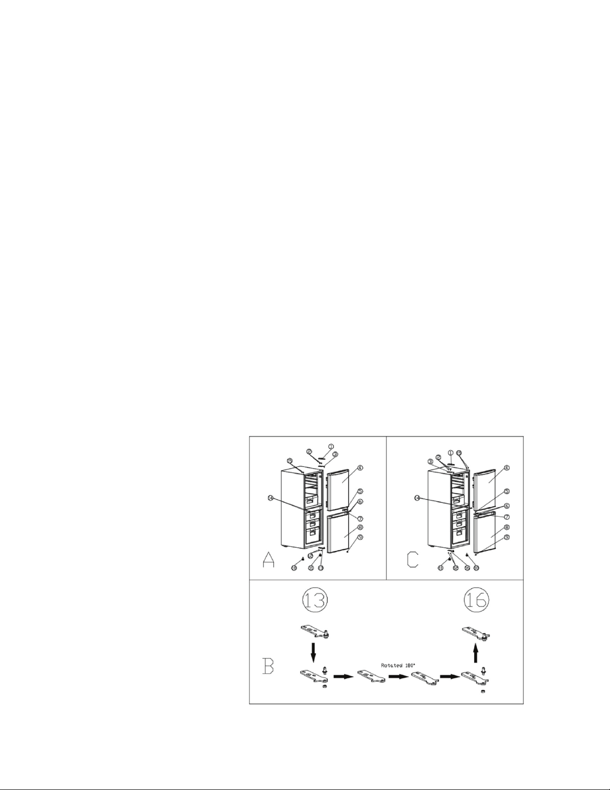
The default left side orientation of the door can be changed to the
right side. Use the following procedure to change the side of the
door hinge.
Tools required: Slot screwdriver, Cross screwdriver, Spanner
1. Set the thermostat to the 0 position and disconnect the power
plug from the electrical outlet.
2. Remove the shelves, crisper and egg tray from the unit.
ăċƫ%(0ƫ0$!ƫ,,(%*!ƫ'3. /ƫ0+ƫ*ƫ*#(!ƫ+"ƫąĆŋƫ* ƫ/!1.!(5ƫ/1,
port it.
ąċƫ*/.!3ƫ0$!ƫ &1/0(!ƫ"!!0ƫĨġāĀĩƫ+*ƫ0$!ƫ+00+)ċ
Ćċƫ*/.!3ƫ0$!ƫ(+3ƫ &1/0(!ƫ"++0ƫĨġāāĩċ
ćċƫ*/.!3ƫý*#!ƫ/.!3/ƫĨġāĂĩƫ* ƫ(+3!.ƫ$%*#!ƫ,.0/ƫĨġāăĩƫ3%0$ƫƫ
ý0ƫ$! ƫ/.!3ƫ .%2!.ƫ0$!*ƫ.!2!./!ƫ0$!ƫ(+3!.ƫ$%*#!ƫ,.0/ƫ* ƫü4ƫ0+ƫ
+0$!.ƫ/% !ƫĨġāăƫ0+ƫāćĩ
Ĉċƫ!)+2!ƫ0$!ƫ".% #!ƫ ++.ƫĨġĉĩ
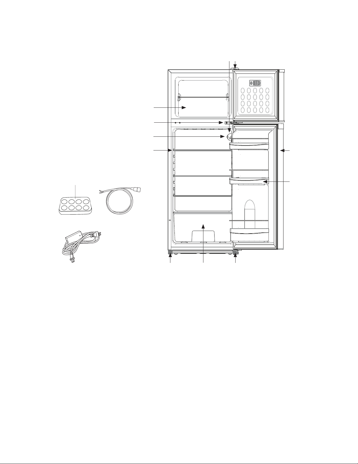
PARTS LIST
PARTS LIST
1: Shelf
Ăčƫ.!!6!.ƫ+),.0)!*0
3: Bulb with cover
4: Thermostat 0 - 7
Ćčƫ++.
6: Upper hinge
7: Lower hinge
ĉčƫ &1/0(!ƫ"!!0
9: Crisper
10: Detachable door rack
11: Middle hinge
12: Egg Tray
13: Power Cable
āąčƫĥƫ(1#ƫĨ+,0%+*(ƫƫƫ
ƫƫƫƫƫ"+.ƫ+*ġ#.% ƫ1/!ĩ
12
13
DOOR REMOVAL AND REVERSAL
AC/DC plug
Ĩ+,0%+*(ƫ"+.ƫ+*ġ#.% ƫ1/!ĩƫ
*sold separately
14
1
2
3
4
5
78
9
10
11
6
9
8. Unscrew the stop block model on the bottom right of fridge door
ĨġĊĩƫ* ƫüƫ4ƫ0$!ƫ/0+,ƫ(+'ƫ)+ !(ƫ0+ƫ0$!ƫ+00+)ƫ+"ƫ(!"0ƫ+"ƫ".% #!ƫ
++.ƫĨġĊĩ
Ċċƫ*/.!3ƫ0$!ƫ)% (!ƫ$%*#!ƫĨġĈĩƫ
āĀċƫ!)+2!ƫ0$!ƫ".!!6!.ƫ ++.ƫĨġąĩ
11. Unscrew the stop block model on the right bottom of freezer
++.ƫĨġĆĩƫ* ƫüƫ4ƫ0$!ƫ/0+,ƫ(+'ƫ)+ !(ƫ0+ƫ0$!ƫ(!"0ƫ+00+)ƫ+"ƫ
".!!6!.ƫ ++.ƫĨġĆĩ
āĂċƫ*/.!3ƫ0$!ƫ$%*#!ƫ,(/0%ƫ,ƫýƫ*#!ƫ/.!3/ƫ".+)ƫ1,,!.ƫ$%*#!ƫ
ĨġāČƫĂČƫăĩƫ* ƫ/.!3ƫ%0ƫ0+ƫ0$!ƫ+0$!.ƫ/% !ƫ+"ƫ0$!ƫ".% #!ƫĨġāČƫĂČƫăĩ
13. Check now if all the hinges and shafts are moved to same side
14. Attach the freezer door to the upper hinge
āĆċƫ00$ƫ0$!ƫ)% (!ƫ$%*#!ƫ0+ƫ0$!ƫ".!!6!.ƫ ++.ƫ* ƫ/.!3ƫ0$!)ƫ
together
16. Attach the fridge door to the middle hinge
17. Attach the lower hinge parts to the fridge door and screw them
0+#!0$!.ƫĨġāāČƫāĂČƫāćĩ
āĉċƫ00$ƫ0$!ƫ &1/0(!ƫ"!!0ƫ+*ƫ0$!ƫ+00+)ƫĨġāĀĩ
19. Cover the top hinge and middle hinge holes with screw caps
20. Put glass shelves, crisper and egg tray in their original position
21. Make sure that the door is in the vertical position and can be
closed easily
PARTS LIST
1. Plastic cap
Ăċƫ(*#!ƫ/.!3ƫĆĵāć
3. Top hinge parts
ąċƫ.!!6!.ƫ ++.
Ćċƫ0+,ƫ(+'ƫ)+ !(ƫ+"ƫ
freezer door
ćċƫ(*#!ƫ/.!3ƫĆ4āĂ
7. Middle hinge
ĉċƫ.% #!ƫ ++.
9. Stop block model of
fridge door
āĀċƫ &1/0(!ƫ"++0
āāċƫ+3ƫ &1/0(!ƫ"++0
āĂċƫ(*#!ƫ/.!3ƫĆ4āć
13. Lower hinge parts
14. Screw caps
āĆċƫ.!3ƫ,/
16. Lower hinge parts
DOOR REMOVAL AND REVERSAL continued
10
IMPORTANT: After reversing the door hinge, the door gasket may be
loose. Should you notice a gap between the gasket and the cabinet,
use a hairdryer or heat gun and heat the gasket while on the appli-
*!ċƫ$!ƫ#/'!0ƫ3%((ƫ!4,* ƫ0+ƫ)!!0ƫ0$!ƫ%*!0ċƫ((+3ƫăĀƫ)%*/ƫ0+ƫ
cool before opening. A correct gasket positioning is the key to pre-
vent refrigerated air from escaping.
THIS FRIDGE MUST NEVER BE CONNECTED DIRECTLY
TO ANY AC (alternating current) POWER SOURCE!
THE FRIDGE MUST ONLY BE CONNECTED TO A 12V OR 24V DC
POWER SOURCE, SUCH AS A SOLAR
BATTERY SYSTEM OR CHARGE CONTROLLER.
THE FRIDGE WILL AUTOMATICALLY OPERATE ON EITHER 12V OR
24V DC. THE USER DOES NOT NEED TO MAKE ANY ADJUSTMENT.
ATTENTION: Polarity is important in wiring this DC appliance. Be
sure that the positive terminal of the battery or charge controller
coincides with the positive wire to the compressor, and the nega-
tive terminal of the battery or charge controller coincides with the
negative wire to the compressor. The leads should be connected
using cable shoes and screwed connections. Joined leads should be
avoided.
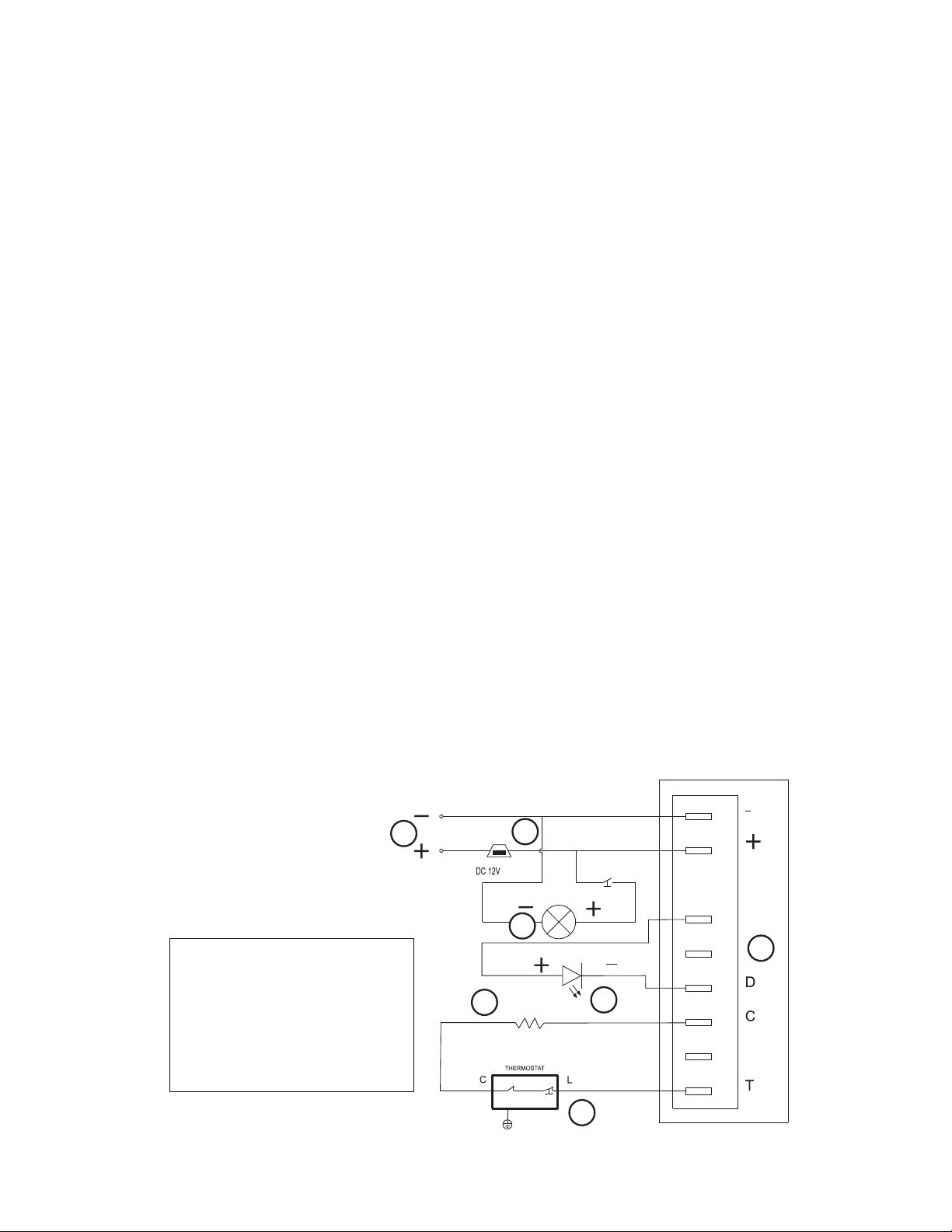
ELECTRICAL DIAGRAM
+ to + and - to -
positive to positive / negative to negative
(red wire) / (black wire)
DC POWER CONNECTION
UGP-260L1 Wiring Diagram
UGP-260L1 Schéma de Câblage
UGP-260L1 Wiring Diagram Label
1: Input power 12VDC /24VDC
2: Fuse 15 A
3: Main PCBA cooling unit
4: Interior light
5: Thermostat
6: LED Error light
7: R1(Speed selection)
1: La puissance d’entrée
12VDC/24VDC
2: Fusible 15A
3: Unité principale de refroid-
issement PCBA
4: Lumiére d’intérieur
5: Thermostat
6: LED (lumiére error)
7: R1 (sélection de vitesse)
WHITE
RED
BROWN
BLACK
YE/GN
P
F+
R E S IS TA N C E
LED errors Light/lumiere errors
Interior Light
1
2
3
5
6
7
BLANC
ROUGE
RED
ROUGE
MARRON
NOIR
BLACK
NOIR
BLACK
NOIR
BLACK
NOIR
BLACK
NOIR
Lumiere Interior
4
JAUNE/VERT
FUSE
FUSIBLE
BLACK
NOIR
RED
ROUGE
6”
4”
UGP-260L1 Wiring Diagram
UGP-260L1 Schéma de Câblage
UGP-260L1 Wiring Diagram Label
1: Input power 12VDC /24VDC
2: Fuse 15 A
3: Main PCBA cooling unit
4: Interior light
5: Thermostat
6: LED Error light
7: R1(Speed selection)
1: La puissance d’entrée
12VDC/24VDC
2: Fusible 15A
3: Unité principale de refroid-
issement PCBA
4: Lumiére d’intérieur
5: Thermostat
6: LED (lumiére error)
7: R1 (sélection de vitesse)
WHITE
RED
BROWN
BLACK
YE/GN
P
F+
R E S I S TA N C E
LED errors Light/lumiere errors
Interior Light
1
2
3
5
6
7
BLANC
ROUGE
RED
ROUGE
MARRON
NOIR
BLACK
NOIR
BLACK
NOIR
BLACK
NOIR
BLACK
NOIR
Lumiere Interior
4
JAUNE/VERT
FUSE
FUSIBLE
BLACK
NOIR
RED
ROUGE
6”
4”
11
IN-LINE FUSE
ƫāĆƫ%*ġ(%*!ƫ"1/!ƫ%/ƫ,.+2% ! ƫ3%0$ƫ0$%/ƫ".% #!ƫ%*ƫ+. !.ƫ0+ƫ,.+0!0ƫ0$!ƫ
wiring. For 12V/24V operation, use a 15A fuse. A standard automo-
bile fuse is recommended and the fuse should be wired to the posi-
0%2!ƫĨėŐĘĩƫ/% !ƫ+"ƫ0$!ƫ/5/0!)ƫ(+/!ƫ0+ƫ0$!ƫ,+/%0%2!ƫ00!.5ƫ0!.)%*(ċƫ
A 15A fuse is provided with this fridge/freezer.
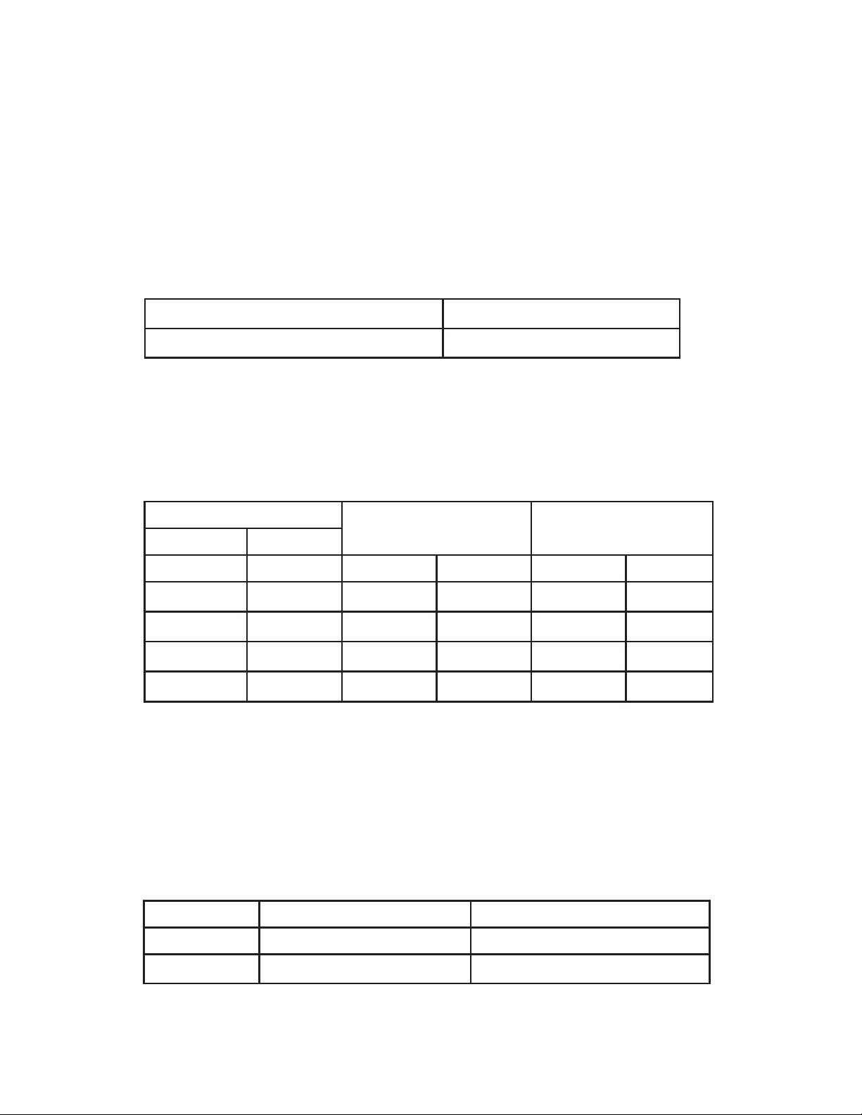
OPERATING VOLTAGE FUSE
12 V / 24 V āĆƫ
DC POWER CONNECTION continued
ATTENTION
If a longer connection cable is necessary, the cable cross section
Ĩ+.ƫ#1#!ĩƫ)1/0ƫ!ƫ!-1(ƫ0+ƫ+.ƫ#.!0!.ƫ0$*ƫ0$!ƫ(!ƫ/%6!/ƫ.!+)-
mended on the following table. Be careful that the input voltage at
the appliance does not drop below the cut-out voltage of the com-
pressor.
CABLE SIZE 12V CABLE
LENGTH
24V CABLE
LENGTH
AREA AWG
mm
2
/inch Gauge m ft m ft
2.5 /
3
/
32
”
12 2.5 8 5 16
4 /
5
/
32
”
12 4 13 8 26
6 /
15
/
64
”
10 6 19.5 12 39
10 /
25
/
64
”
8 10 32.8 20 65.6
LOW VOLTAGE DISCONNECT
The compressor electronics includes a low voltage disconnect fea-
01.!ċƫƫ"ƫ0$!ƫ%*,10ƫ2+(0#!ƫ0+ƫ0$!ƫ,,(%*!ƫ"((/ƫ!(+3ƫāĀċąƫĨ%*ƫāĂƫƫ
)+ !ĩƫ+.ƫĂĂċĉƫĨ%*ƫĂąƫƫ)+ !ĩČƫ0$!ƫ+),.!//+.ƫ3%((ƫ/$10ġ+ûċƫƫ*!ƫ
0$!ƫ2+(0#!ƫ%*.!/!/ƫ+2!ƫāāċĈƫĨ%*ƫāĂƫ)+ !ĩƫ+.ƫĂąċĂƫĨ%*ƫĂąƫ
)+ !ĩČƫ0$!ƫ+),.!//+.ƫ3%((ƫ.!/1)!ƫ*+.)(ƫ+,!.0%+*ċƫƫ
$%/ƫ"!01.!ƫ%/ƫ !/%#*! ƫ0+ƫ,.+0!0ƫ0$!ƫ/5/0!)ƫ00!.5ƫ".+)ƫ!4,!.%-
encing too low a depth of discharge.
12 V OPERATION 24 V OPERATION
ġ 10.4 V 22.8 V
RESTART 11.7 V 24.2 V