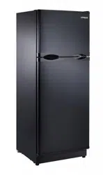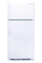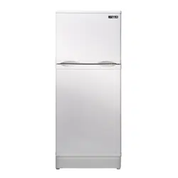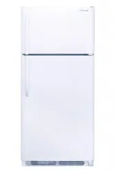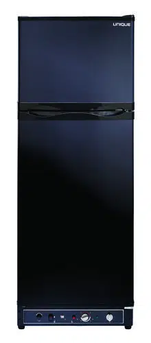
UNIQUE ‐Models UGP 6C/8C/10C
Propane Refrigerators - Installation and Owners
Manual
The installation of the appliance must conform with local codes or,
in the absence of local national Fuel Gas Code, ANSI Z233.1 and in Canada
B149.2 Propane Storage and Handling Code
WARNING: Improper installation, adjustment,
alteration, service or maintenance can cause
injury or property damage. Refer to this manual.
For assistance or additional information consult a
qualified installer, service agency or the gas
supplier.
!SAVE THESE INSTRUCTIONS!
FOR YOUR SAFETY IF YOU SMELL GAS
Open windows.
Do not touch electrical switches.
Extinguish any open flame
Immediately turn off gas supply and call your gas supplier
FOR YOUR SAFETY
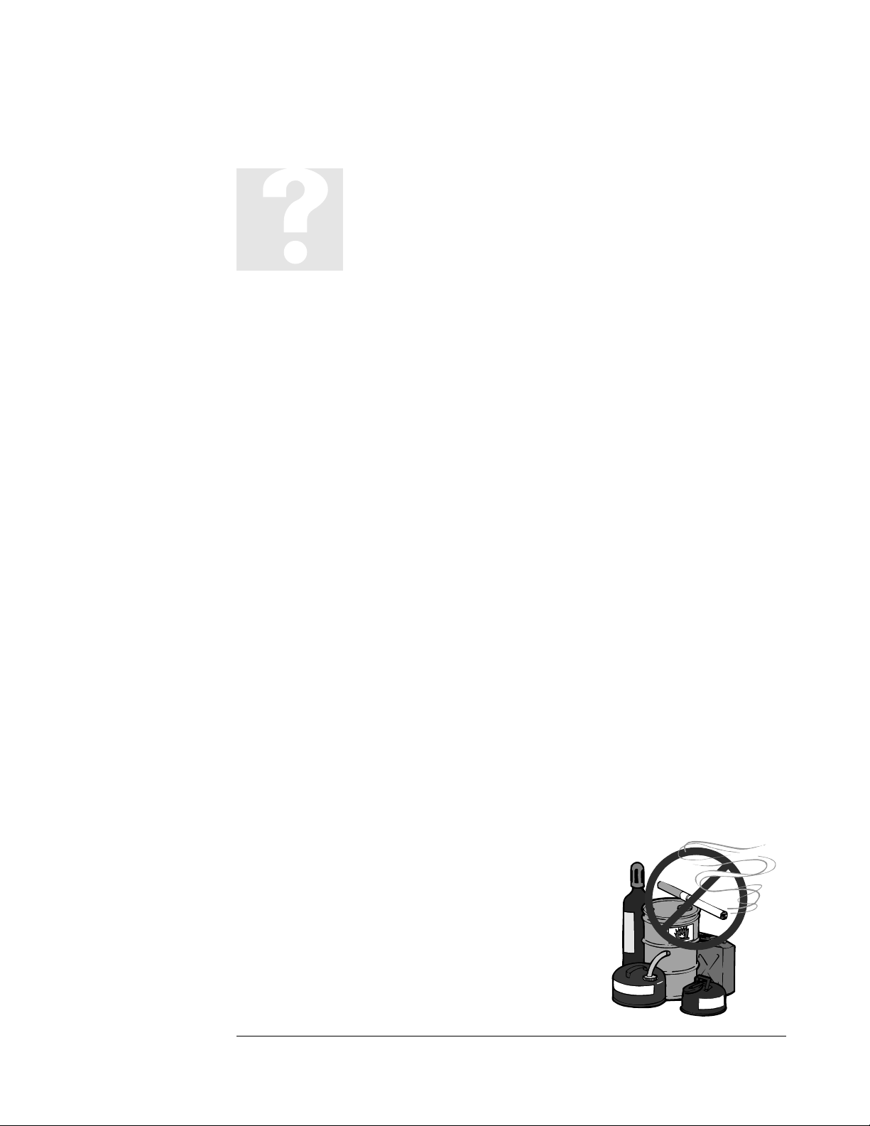
Do not store or use gasoline or other flammable and liquids in the
vicinity of this or any other appliance
Ma
y
2012

NOTICE TO INSTALLER/CUSTOMER
Please read carefully before hook-up!
1. The dwelling must have an adequate air supply and access to fresh air/oxygen in order to operate safely. Propane fridges/freezers,
like any other gas appliance, must have access to fresh air/oxygen. This unvented appliance must not be used in an air-
tight application.
2. This refrigerator must be installed by a licensed gas fitter.
3. The propane gas supply pressure regulator must be set at 11” water column.
4. The left side heat shield (facing front of the refrigerator) must be installed. The heat shield is shipped in the refrigerator carton.
5. For safety & efficient operation the proper clearances on all sides and top must be maintained. The clearances are listed in the
Owner’s Manual.
6. For proper and efficient operation the refrigerator must be level, both side to side and front to back (use bubble type level).
7. The Combination Carbon Monoxide (CO) Alarm & Safety Shut-Off must be installed and connected (CM Models only) with the Alarm
mounted as indicated in the Carbon Monoxide Alarm (Monitor) Installation Manual.
NOTE: It is illegal to operate this refrigerator in Canada without the Combination Carbon Monoxide Alarm & Safety
Shut-Off installed, and will void the Canadian Standards Association Certification. Non compliance will void the
Canadian certification and void household/cottage insurance coverage. This refrigerator vents combustion products
directly into the living space. The CO Alarming Device with Safety Shut-Off has been added to this refrigerator to guard against
potentially high levels of Carbon Monoxide, which can kill you. Once unsafe levels of CO are detected, an alarm will sound and the
refrigerator will be shut off.
WARNING: Actuation of this device indicates the presence of unsafe levels of carbon monoxide (CO) which can KILL YOU. If
alarm signal sounds:
a. Immediately move to fresh air --- outdoors or by an open door or window. Check that all persons are accounted for. Do not
re-enter the premises or move away from the open door/window until the emergency services responders have arrived, the
premises have been aired out, and your alarm remains in its normal condition;
b. Call emergency local service telephone number, fire department or 911.
c. The following symptoms may be related to CARBON MONOXIDE POISONING and should be discussed with ALL members of the
household:
Mild Exposure: Headaches, running nose, sore eyes, often described as “flu”-like symptoms;
Medium Exposure: Dizziness, drowsiness, vomiting;
Extreme Exposure: Unconscious, brain damage, death.
d. Read the Instructions for complete Information on Alarms Signals.
8. NOTE: The Combination Carbon Monoxide Alarm & Safety Shut-Off Instructions (CM Model), battery, Owners/Installation Manual
are stored inside the refrigerator.
For Unique Gas Products Support, Call Toll Free 1-877-427-2266
9. Regular maintenance of the fridge is critical to prevent unsafe levels of Carbon Monoxide. Before lighting the refrigerator at any
time, clean the flue tube as per the Owner’s Manual & make sure the burner and areas around the burner are free from any lint,
spider webs or any other debris. Please record your appliance maintenance on the SERVICE RECORD label located at the back of
your appliance.
WARNING -- Test the Combination Carbon Monoxide & Safety Shut-Off device operation after the refrigerator has been in storage,
before each start up , and at least once per week during use.
The installation of the refrigerator must conform to the Local Codes. In the absence of a local code:
USA: Nation Fuel Gas Code
Canada: CSA B149.1 Natural Gas & Propane Installation Code
CSA B149.2 Propane Storage and Handling Code

CERTIFIED AND DISTRIBUTED BY
Unique Gas Products Ltd
Unique Gas Products Ltd,
2245 Wyecroft Road #5
Oakville, Ontario, Canada, L6L 5L7
Ph: 905-827-6154 Toll Free: 1-877-427-2266 Fax: 905-827-2027
www.UniqueOffGrid.com
E-mail: info@uniqueoffgrid.com
“
“
P
P
E
E
R
R
S
S
O
O
N
N
A
A
L
L
S
S
E
E
R
R
V
V
I
I
C
C
E
E
&
&
K
K
N
N
O
O
W
W
L
L
E
E
D
D
G
G
E
E
M
M
A
A
K
K
E
E
S
S
U
U
S
S
U
U
N
N
I
I
Q
Q
U
U
E
E
”
”

Table of Contents
Chapters
Welcome 1
Safety and Warnings 1
Appliance Installation 2
General Operating Instructions 3
How to use the Refrigerator 3
Maintenance & Service 4
Troubleshooting & Suggested Spares 5
Carbon Monoxide Instructions (CM Model) 6
Door Reversal and Removal Instructions 7
Temperature Controls, Food Storage and
Cleaning 8
Parts & Warranty 9
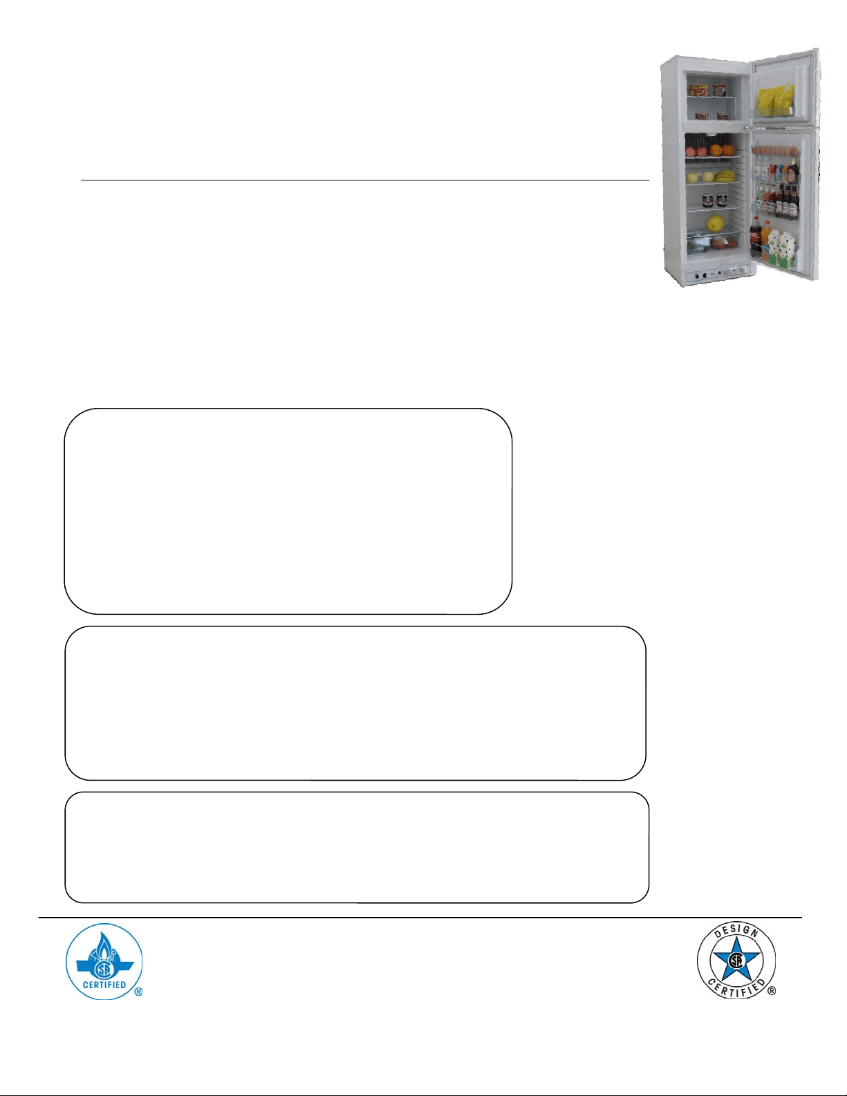
MODELS UGP 6C/8C/10C
1
Welcome &
Congratulations
ongratulations on your purchase of a UNQIUE refrigerator!. We are very
proud of our product and we are completely committed to providing you with
the best service possible. Your satisfaction is our #1 priority. Please read this
Manual very carefully. It contains valuable information on how to properly maintain
your new gas refrigerator.
We know you will enjoy your new refrigerator and Thank You for choosing one of our
Unique Gas Products. We hope you will consider us for future purchases.
PLEASE READ AND SAVE THESE INSTRUCTIONS
This manual provides specific operation instructions for your model. Use your
refrigerator only as instructed in this manual. These instructions are not meant to cover
every possible condition and situation that may occur. Common sense and caution
must be practiced when installing, operating and maintaining the appliance
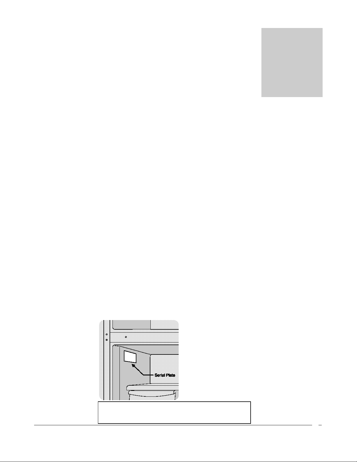
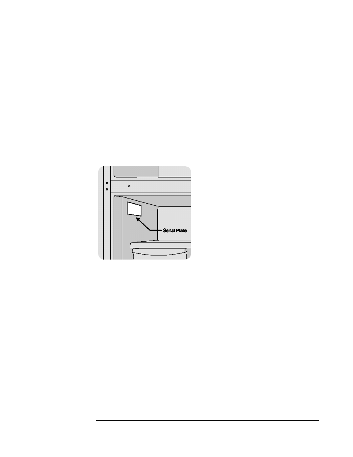
Please record your model and serial # shown below for future reference. This
information is found on your CSA rating/serial plate inside the refrigerator
compartment.
Chapter
1
C
Please mail in the Warranty Registration Card
included with you refrigerator.
Safety and Warnings
If you smell gas
Open Windows
Don’t touch electrical switches
Extinguish any open flame
Immedialty call your gas supplier
For you Safety
Do not store or use gasoline or other flammable vapors and liquids in the
vicinity of this unit or any other appliance
Warning
Improper installation, adjustment, alteration, service or maintenance can cause
injury or property damage. Refer to this manual. For assistance or additional
information consult a qualified installer, service agency or the gas supplier.
This product can produce Carbon Monoxide. Carbon Monoxide has no odour
and can kill you. The burner and flue system must be kept clean. See owner’s
manual for cleaning instructions.
Installation Instructions
The installation of the appliance must conform with local codes or, in the
absence of local national Fuel Gas Code, ANSI Z233.1 and in Canada B149.2
Installation
For best performance at high ambient temperatures, there must be free air
circulation over the cooling unit at the rear of the refrigerator.
Ensure that there is a free air space above the refrigerator and that the flue
(chimney) on top of the cabinet is not covered in any way. Do not place the
refrigerator in a space where air circulation is restricted. Follow “clearance”
instructions.
This free-standing refrigerator requires accessibility to the back for servicing the
gas equipment, which can be obtained by using a certified Flexible Metal
Connector to allow the refrigerator to be withdrawn without disrupting the gas
supply. “Where a flexible metal connector is used, it must comply with local
authorities and in Canada with the provisions of the current Standard CAN 1-
6.10, Metal Connectors for Gas Appliances”. However, if the Local Authorities
require a rigid gas supply connector, the refrigerator should be located with
sufficient space at the back for servicing or, if located against a wall a removable
panel of a minimum size of 16” x 20” should be provided in the wall to allow
access to the rear of the refrigerator. . If you purchased a CM (CO Monitor
model) you must follow instructions in Section 6 - 5.0 onward.
Heat Shield
The heat shield must be installed before operating the
appliance. This is a CSA requirement.
Un-wrap the heat shield (located inside the box along
with the appliance). Mount heat shield with the
screws (supplied) to right side of the fridge.
Chapter
2
Heat Shield
A
ir Flow - to release heat trap
6”
6”
Clearances
Minimum clearances to combustible materials are:
Top – 6”
Sides – 2”
Rear – 1”
as shown in Figures. 1, 2 & 3.
Note: DO NOT install the appliance directly on carpeting. Carpeting must
be removed or protected by a metal or wood panel beneath the appliance,
which extends at least the full width and depth of the appliance.
Fig#1 - This is ideal as both top and sides are open
Fig#2 – During hot/humid weather this confined area will become very
warm. To reduce heat build-up, we recommend providing an area for two air
vents to circulate the air. One placed 6” off the floor and the other at or above
the appliance top. Cold air return vents with adjustable louvers, works very
well. This will allow hot air to evacuate the area and assist in air flow across the
fins (similar to air passing across a radiator) – See Fig #4
Fig#3 – If this is your opening you only need to stay the diagrammed distance
from the wall and ceiling. There is no need for additional venting.
Gas Connection
Hook-up to the gas supply line: 3/8” SAE (UNF 5/8” - 18) male flare connection. A
backup wrench must be used when tightening gas supply fitting. All completed

connections should be checked for leaks with a non-corrosive leak detector and/or
soap and water for a bubble check..
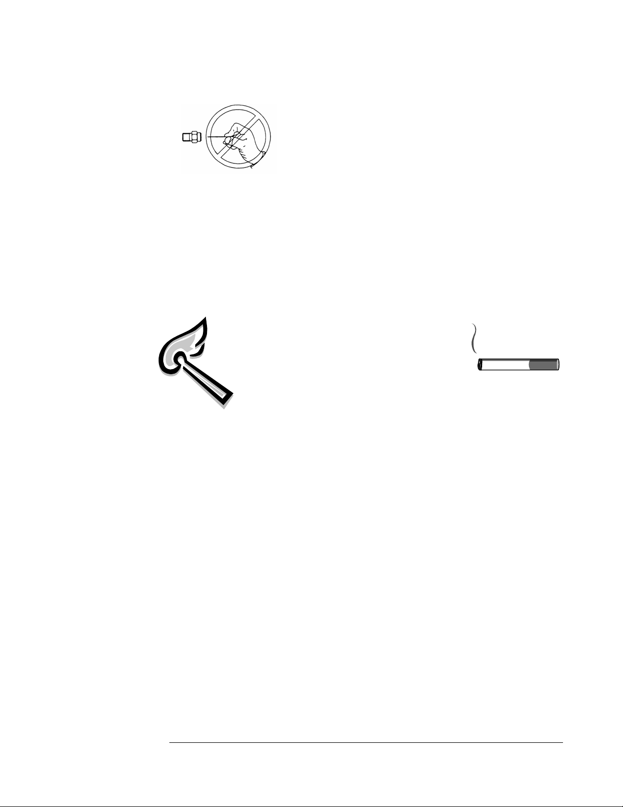
WARNING – DO NOT USE FLAME TO CHECK FOR GAS LEAKS
The gas supply system must incorporate a pressure regulator to maintain a supply
pressure of not more than 12” water column and no less than 11” water column. (max
setting)
Make sure the refrigerator and any other high BTU appliances on your line are turned
on when checking the gas pressure. The appliance and its individual shut-off valve
must be disconnected from the gas supply piping system during any pressure testing of
that system at pressures in excess of ½” psig.
In case detailed instructions on the installation and connection of the gas supply are
required, contact your dealer or distributor.
Levelling
Ensure the fridge is level by using a 2ft level. Level the fridge front to back and
left to right using the top of the appliance. There are no levelling legs at the back
of the appliance just at the front; if the back if your floor is uneven you will have
to use shims of some sort to ensure the appliance is level. See importance of level
explained on next page.

General Operating Instructions
Importance of Leveling a Refrigerator
The refrigerator must be adjusted to a vertical position in both directions. In an
absorption refrigeration system, ammonia is liquefied in the finned condenser coil at
the top rear of the refrigerator. The liquid ammonia then flows into the evaporator
(inside the freezer section) and is exposed to circulating flow of hydrogen gas, which
causes the ammonia to evaporate, creating a cold condition in the freezer.
When starting this refrigerator for the very first time, the cooling cycle may require up
to 4 to 6 hours of running time before the cooling unit is fully operational to begin
slowly loading compartment with cold food from your cooler.
The tubing in the evaporator section is specifically sloped to provide a continuous
movement of liquid ammonia, flowing downward by gravity through this section. If
the refrigerator is operated when not level, liquid ammonia will accumulate in sections
of the evaporator tubing. This will slow the circulation of hydrogen and ammonia gas,
or in severe cases, completely block it, resulting in a loss of cooling. Warranty will not
cover recharge/rebuild if caused by not running the fridge level.
This refrigerator operates on LP Gas (Propane) & 110V (Electricity)
Note: After changing an LP tank, or after a long shut off period, the gas line is likely to be filled with
air. You may have to repeat the lighting procedure several times to purge the air out of the gas lines. We
suggest first turning off gas at the control panel, then the tank, this will reduce an air trap in the gas
line.
Gas Operation – for models with both piezo or electronic ignition
“Start Up” Procedure
Piezo Ignition
1. To start the refrigerator, turn the thermostat knob E to maximum setting.
Chapter
3

2. Turn button G to Gas position, then push A button in and hold for the electronic
igniter to light the burner, if no electronic ignition exists then repeatedly press A,
continue to hold the D button until you see the needle on the flame sensor C has
moved from the white into the green area. The burner should now be “on”, if not
repeat the lighting instructions above. Once in green zone for 15-30 seconds,
release D button. If there is no click sound while depressing the A button the
batteries need changing.
3. Adjust the thermostat knob to desired temperature setting after 4 to 8 hours
of operation.
Electronic Ignition (battery)
1. To start the refrigerator, turn the thermostat knob E to maximum setting.
2. Turn button G to Gas position, then push A button in and hold for the electronic
igniter to light the burner, continue to hold the D button until you see the needle
on the flame sensor C has moved from the white into the green area. The burner
should now be “on”, if not repeat the lighting instructions above. Once in green
zone for 15-30 seconds, release D button. If the is no click sound while depressing
the A button the batteries need changing.
3. Adjust the thermostat knob to desired temperature setting after 4 to 8 hours
of operation.
4. To change the batteries in the electronic ignition button to the left to expose
the battery, remove AA battery and replace with new one, replace the knob
and turn the to the right to close.
Note: If using CO-Monitor, the monitor must be hooked up and be reset with
the battery installed for the flame to stay on – Refer to Chapter 6
Shut Down Procedure – Gas Operation
1. Turn selector knob G to the OFF position
2.
Shut the gas off at the LP-gas supply cylinder when the appliance is not in use.
3. If the refrigerator will not be in operation for a period of weeks, it should be
emptied, defrosted, cleaned and the doors left open.
110V Operation
1. Ensure the electrical cord is plugged into a grounded outlet
2. Turn the selector switch G to AC position, AC power indicator F will
illuminate
3. To start the refrigerator, turn the thermostat knob E to maximum setting.
4. Adjust the thermostat knob to desired temperature setting after 4 to 8 hours
of operation.
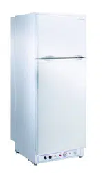
CONTROLS – See Fig 5. for description of controls
Thermostat
The refrigerator cooling temperature is controlled by a combination thermostat that
can be adjusted by turning knob E to different settings to maintain the desired
refrigerator temperature. It also incorporates a safety device which automatically shuts
off the supply of gas if the flame goes out. The piezo electric igniter and/or the
electronic ignition discharges sparks onto the burner when the appropriate button is
pushed. See Figure #4
1. “MIN” Setting on the Gas Thermostat: In gas operation, the thermostat closes
its main valve and the burner runs continuously at the bypass rate or pilot flame.
(counter clockwise turn)
2. “MAX” Setting of the Thermostat: In gas operation, the thermostat allows the
burner to remain on high flame continuously. (Clockwise turn)
3. The thermostat can be adjusted between “Max” and “Min” (4 or 1) to obtain the
desired fridge temperature.
When the thermostat reaches the set temperature, it will cut the burner back to bypass
operation.
Figure #5
A B C D E F G

The setting of the thermostat is critical and recommend it be adjusted to maintain a dry
frost on the cooling fins (approx 38 Freinhight or 3 Celsius). Adjust the thermostat
knob closer to “Max” (clockwise) when the outside temperature rises.
NOTE: When first turning refrigerator on, move refrigerator controls to maximum,
which is the recommended initial setting. After 24 hours, adjust the controls as needed.
How To Use The Refrigerator
FOOD STORAGE COMPARTMENT
The food storage compartment is completely closed and unventilated, which is
necessary to maintain the required low temperature for food storage. The coldest areas
in the refrigerator are under the cooling fins and at the bottom of the refrigerator. The
warmer areas are on the upper door shelves. This should be considered when placing
different types of food in the refrigerator.
FROZEN FOOD STORAGE COMPARTMENT
Quick frozen soft fruits and ice cream should be placed in the coldest part of the
compartment which is at the bottom. Frozen vegetables, may be stored in any part of
the compartment.
This compartment is not designed for deep or quick freezing of food. Meat or fish,
whether raw or prepared, can be stored in the frozen food storage compartment
provided they are pre-cooled in the refrigerator. To prevent food from drying out,
keep it in covered dishes, containers, plastic bags or wrapped in aluminum foil.
Defrosting
Frost will gradually accumulate inside the refrigerator and freezer surfaces. It must not
be not allowed to grow too thick as it acts as an insulator and adversely affects the
refrigerator performance. Check the formation of frost every couple of weeks and
when it exceeds 1/2” thick or more defrost the refrigerator.
Shut off and empty the refrigerator, leaving the fridge and the freezer doors open.
Defrosting time can be reduced by filling the ice tray with hot water and placing it in
the freezer compartment. You can also open the doors without shutting off the
appliance to defrost the fridge; the process will just be a bit slower.
DO NOT USE A HOT AIR BLOWER, PERMANENT DAMAGE
COULD RESULT
, DO NOT USE A KNIFE, AN ICE PICK,
OR ANY OTHER SHARP TOOLS TO REMOVE FROST
FROM THE FREEZER COMPARTMENT
.
FRIDGE SECTION
Inside the refrigerator compartment, the defrost water runs from a collector channel to
a drip tray/cup at the rear of the refrigerator where it normally evaporates. If heavy
frost has built up on the cooling fins creating a lot of defrost water, Beware your
water reservoir may overflow, we suggest you inspect reservoir before/after
cycle.
FREEZER SECTION
This area must be wiped down with cloths to remove water after defrosting; there is no
drain for this compartment
When all frost is melted in the freezer compartment & interior of the refrigerator it
should be wiped up with a clean cloth. Replace all food and set the thermostat to your
desired setting.
Cleaning
Cleaning the refrigerator is usually done after it is defrosted or put into storage. To
clean the interior liner of the refrigerator, use lukewarm weak soda solution. Use only
warm water to clean the finned evaporator, gasket, ice trays and shelves.
Never use strong chemicals or abrasives to clean these parts as the
protective surfaces will be damaged. It is important to always keep the
refrigerator clean. Dishwasher detergent is recommended
Inside Light
The interior light turns on when the door is open. The light uses four AA batteries
located at the back of the appliance.
To change the batteries, use the following procedure:
1. Go to the back of the appliance and remove the cover held in place by 4 Phillips
screws
2. Remove and replace the 8 x AA batteries

3. Replace the cover and 4 Phillips screws
4. The light will come on when the fridge door is open, and will shut off when
the fridge door is closed by a switch located at the upper right hand side of the
inner portion of the fridge. You can check its operation by manually pressing
and releasing the switch.
Shut Down Procedure
A. Turn gas valve knob to the “off” position
B. If the refrigerator will not be in operation for a period of weeks, it should be
emptied, defrosted, cleaned and the doors left open. The ice tray should also be
dried and kept outside the cabinet, also turn off gas at the main supply source.

Maintenance & Service
The user should be aware of service that must be done on a regular schedule to keep
the refrigerator operating properly. Installation must be by a licensed gas fitter in
accordance with local codes or in the absence of local national Fuel Gas Code, ANSI
Z233.1 and in Canada B149.2 Propane Storage and Handling Code (latest edition).
REFRIGERATOR REMOVAL and PERIODIC MAINTENANCE
Before working on the refrigerator, shut off the gas supply. Disconnect the gas supply
line at the rear of the refrigerator. Always use a back up wrench when loosening and
tightening this connection. Cap the gas supply line and remove the refrigerator.
Replacement is the reverse of removal. Check all connections for gas leaks.
Refer to Chapter 2 - Installation
To keep your refrigerator operating effectively and safely, periodic inspection and
cleaning of several components is recommended once or twice a year, sometimes more
often depending on environment.
It's important to keep the area at the back of the refrigerator clean. Clean the coils
on the back of the refrigerator. Use a soft bristled brush to dust off
the coils.
Note:
The following maintenance is required at least once
or twice a year at least.
Check all connectors in the complete refrigerator LP gas system for gas leaks.
The LP gas supply must be turned on. Apply a non corrosive bubble solution
to all LP connections. The appearance of bubbles indicates a leak and should
be repaired immediately by a qualified serviceman.
WARNING – DO NOT USE FLAME TO CHECK FOR GAS LEAKS
Chapter
4
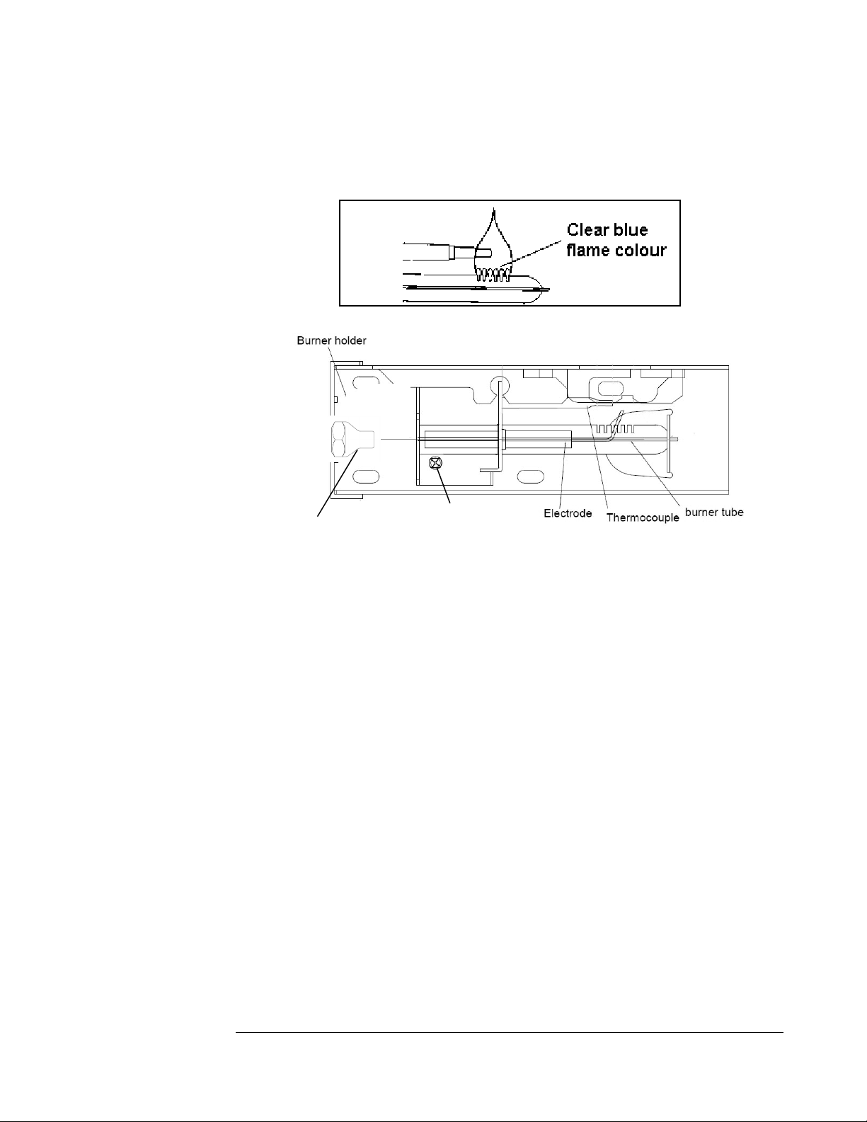
Check burner flame for proper appearance. The flame should be light blue with no
yellow at the tip. See figure #6
The LP gas pressure should be checked and the main regulator readjusted if
pressure is incorrect. The correct operating pressure is 11” W.C. (water
column).
Inspect the flue baffle, it should be clean and free of soot. Any soot formation
indicates improper functioning of the burner. The flue and burner both
require cleaning in the following manner:
o
Remove cover from the burner housing.
o
Remove the burner by removing the burner mounting screw
o
Remove the wire and flue baffle from the top of flue tube. Clean the
flue from the top using a flue brush and be sure to cover the burner
if remaining intact to eliminate dirt falling into burner. Blowing
compressed air into the flue should clean out soot and scale. Replace
the flue baffle.
o
Clean burner tube with compressed air, check for fluff or spider webs.
o
Before removing burner orifice, clean burner area of any soot, scale or
dirt. Remove the orifice/burner jet and soak it in alcohol (isopropyl
alcohol or thinners) and blow it out with compressed air. Re-install
and tighten burner orifice.
o Replace burner
Fig. #6
Fig. #7
Burner Mounting Screw
Burner Jet/Orifice
Warning - DO NOT use a pin or wire when
cleaning the burner orifice as damage can
occur to the precision opening. This can
cause damage to the refrigerator or create
a fire hazard. It will also create extremely
dangerous levels of carbon monoxide.
o The inlet & outlet gas fittings on the refrigerator need to be checked
for leaks. Apply a non corrosive bubble solution to the fittings and
observe for leaks. The safety valve will not allow gas pressure to any
connections between it and the burner orifice. These fittings must be
checked while burner is in operation (gas flow will be present between
safety valve and burner head)
WARNING – The gas button D Fig#5 must
be manually depressed to allow gas pressure to
flow to the burner orifice. Be sure to apply the
leak check solution before depressing the safety
shut–off. DO NOT allow any open flame,
sparks, smoking, etc. in the area of the test. DO NOT depress safety
shut-off for over 30 seconds.
o If leak occurs, then allow ten minutes to dissipate from the burner
area. Fix leak then light the burner according to the instructions under
GENERAL OPERATING INSTRUCTIONS – GAS OPERATION, CHAPTER 3

TROUBLESHOOTING INSTRUCTIONS &
SUGGESTED SPARE PARTS TO KEEP ON HAND
REFRIGERATOR DOES NOT COOL, CHECK LIKELY CAUSES:
1.
Burner orifice clogged. Clean. See section Maintenance & Service, CHAPTER 4,
2.
Check to ensure refrigerator is level – (left to right and front to back).
3.
Restriction on air flow across cooling unit.
4.
Heavy frost build-up on evaporator fins. Defrost.
5.
Flue baffle not inserted properly in flue tube.
6.
Improperly set thermostat. See paragraph on thermostat. In hot weather or heavy
use the setting should be closer to “Max” than usual.
7.
Burner dirty. Clean. See Section MAINTENANCE & SERVICE, CHAPTER 4,
PERIODIC MAINTENANCE
8.
LP gas pressure low at burner. Regulator pressure must not drop below 11 inches
W.C (water column). CHAPTER 2, GAS CONNECTION
9.
Burner not located properly under the flue tube. Relocate, flame must be directly
into flue
10.
Burner damaged. Replace.
11.
Odours and fumes
Dislocated burner
Damaged Burner
Dirty orifice
Dirty flue tube – CHAPTER 4.
Chapter
5
Spare Parts
The following is a list of commonly used parts which are available:
Burner orifice
Burner
Electrode with wire
Thermocouple
Combination Safety valve & Thermostat
Baffle
Contact your dealer or an authorized service center for parts and repairs as needed.
Quote Model & Serial # - See CSA rating/serial plate on inside left wall.

Carbon Monoxide Monitor Instructions for
Model - UGP-6C/8C/10C
Unique to Canada only
OWNER’S MANUAL
Model 9RV-SSO
Carbon Monoxide Alarm for Appliance Safety Shutoff
ATTENTION: PLEASE READ, FOLLOW AND SAVE!
(See Additional Instruction Sheet for Safety Shutoff Connection)
Dear New COSTAR 9RV-SSO Owner,
Congratulations as you have taken steps to help insure the health and life safety of
you and your family. We are proud to offer you our unique, patented CO Sensor
technology that detects CO in a manner similar to the human body's response.
Please read this owner's manual carefully so you will have a better understanding
of the effects of CO poisoning and the COSTAR 9RV-SSO Alarm in
conjunction with our UNIQUE propane refrigerator.
To your good health and safety,
Unique Gas Products
WARNING: Failure to replace this product by the “REPLACE BY DATE”
printed on the alarm cover may result in death by Carbon Monoxide poisoning.
Chapter
6

Replace by date is six (6) years from date of manufacture.
1.0 WHAT YOU SHOULD KNOW ABOUT CO
Carbon monoxide (CO) is an insidious poison. It is a colorless, odorless and
tasteless gas. It is a cumulative poison. The following symptoms are related
to CARBON MONOXIDE POISONING and should be discussed with
ALL members of the household:
MILD EXPOSURE
Slight headache, nausea, vomiting, fatigue (often described as "flu–like"
symptoms)
MEDIUM EXPOSURE
Severe throbbing headache, drowsiness, confusion, fast heart rate
EXTREME EXPOSURE
Unconsciousness, convulsions, cardio respiratory failure, death
Many cases of reported CARBON MONOXIDE POISONING indicate
that while victims are aware they are not well, they become so disoriented
they are unable to save themselves by either exiting the building or calling
for assistance. Also, young children and household pets may be the first
affected.
Your CO alarm is designed to detect the toxic CO fumes that result from
incomplete combustion, such as those emitted from appliances, furnaces,
fireplaces and auto exhaust. A CO Alarm is NOT A SUBSTITUTE for
other combustible gas, fire or smoke alarms. This carbon monoxide alarm is
designed to detect carbon monoxide gas from ANY source of combustion.
CAUTION: This alarm will only indicate the presence of carbon monoxide
gas at the sensor. Carbon monoxide gas may be present in other areas.
CAUTION: This product is intended for use in ordinary indoor locations
of family living units. It is not designed to comply with Occupational Safety
and Health Administration (OSHA) commercial or industrial standards.
Individuals with medical problems may consider using warning devices that
provide audible and visual signals for carbon monoxide concentrations
under 30 ppm. .

2.0
WHAT YOU SHOULD DO IF THE ALARM SOUNDS
WARNING: Activation of this device indicates the
presence of carbon monoxide (CO) which can KILL
YOU. If alarm sounds:
For Users in the United States, follow the protocol in steps 1
through 4 below:
1 Operate reset/silence button;
2 Call your emergency services (____ - ______) [fire department or 911];
3 Immediately move to fresh air – outdoors or by an open door/window.
Do a head count to check that all persons are accounted for. Do not
reenter the premises nor move away from the open door/window until
the emergency services responders have arrived, the premises have been
aired out, and your alarm remains in its normal condition.
4 After following steps 1-3, if your alarm reactivates within a 24 hour
period, repeat steps 1-3 and call a qualified technician (____ - ______) to
investigate for sources of CO from fuel burning equipment and
appliances, motor vehicles or other sources and inspect for proper
operation of this equipment. If problems are identified during this
inspection, have the equipment serviced immediately. Note any
combustion equipment not inspected by the technician and consult the
manufacturers' instructions or contact the manufacturers directly for
more information about CO safety and this equipment. Make sure that
motor vehicles are not and have not been operating in an attached garage
or adjacent to the residence.
For users in Canada, follow the protocol in steps 1 and 2 below:
1. Immediately move to fresh air/outdoors or by an open door or window.
Check that all persons are accounted for. Do not re-enter the premises or
move away from the open door/window until the emergency services
responders have arrived; the premises have been aired out, and your alarm
remains in its normal condition;
2. Call your emergency services ( ___ - ________ ) [ fire department or 911
]; If “service” signal sounds (RED LED flashes and horn beeps every 30
seconds); contact your retailer the manufacturer for troubleshooting
and/or instructions to return the unit:

2.1 IMPORTANT CONSIDERATIONS:
The COSTAR
9RV-SSO has been designed and is warranted to operate for
six years. Never disconnect the battery to silence an alarm. The alarm will
automatically sense when the level of CO in the air falls below the danger
level. You should stay outside the residence or unconditioned area and
remain in fresh air until the alarm is silenced. When the alarm sounds, do
not stand too close to the alarm. The sound produced by the alarm is loud
because it is designed to awaken a person in an emergency. Prolonged
exposure to the alarm at a close distance may be harmful to your hearing.
3.0 DEVELOPING YOUR OWN CO SAFETY PLAN
This CO alarm can quickly alert you to the presence of CO — it cannot
prevent toxic CO emissions. Please note that there are hazards against which
CO detection may not be effective, such as gas leaks or explosions. The
ultimate responsibility for protection against toxic CO fumes rests solely on
you. Installing CO detectors is just the first step in protecting your family
from toxic CO poisoning. We also suggest that you create an effective,
comprehensive safety program as outlined below.
3.1 Install CO detectors properly following the instructions in this manual.
3.2 Develop a family escape plan and practice it with your entire family,
especially small children.
– Draw a floor plan of your home and find two ways to exit from each
room. There should be one way to get out of each bedroom without
opening the door.
– Make sure that all occupants know what the CO alarm signal means and
how they must exit the residence by themselves if necessary.
– Decide on a meeting place a safe distance from your house and make
sure all occupants understand where they should go and wait if there is a
dangerous CO condition.
– Conduct CO safety drills at least every 6 months to make sure that
everyone, even small children, know what to do in order to escape
safely.
– Know where to go to call the Fire Department or professional assistance
from outside your residence.
– Know where to go call the emergency service provider and or a qualified
service technician.
4.0 IMPORTANT: WHAT YOUR CO ALARM CAN AND CANNOT
DO
4.1 This unit is designed to detect carbon monoxide (CO) and shutoff an
appliance for safety only.
4.2 This CO alarm is designed for use within a single residential living
unit. It is designed to detect carbon monoxide (CO) entering its
sensing chamber. It does not sense combustible gas (such as natural
gas, propane or (butane), heat, smoke or flames
4.3 This CO alarm may not provide early warning for occupants if it is
placed outside of the house, such as on outside porches.
4.4 When properly located, installed, and maintained, this CO alarm is
designed to provide early warning of developing poisonous CO
conditions at a reasonable cost. This alarm monitors the air, and when it
senses CO, it activates its built-in alarm. It can provide precious time for
you and your family to escape from your residence before CO can
seriously injure or kill. However, such an early warning is possible only if
the alarm is located, installed, and maintained as specified in the Owner's
Manual and the Instruction for the Safety Shutoff Connection.
5.0 INSTALLING THE COSTAR
9RV-SSO
5.1 One of the most important considerations in any CO alarm system is the
location of the alarms. Statistics of the National Fire Protection
Association (NFPA) show that most of the fatal CO occurrences happen at
night while people are sleeping and/or while they are in the garage. Early
warning of CO is best achieved by the correct installation of CO alarms.
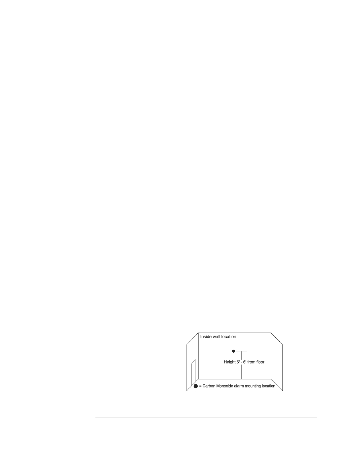
5.2 This CO alarm may be mounted on the wall.
WALL LOCATION:
Mount the alarm at least
3 feet (usually 5 – 6 feet)
from the floor.
Figure 1:
Recommended CO alarm wall

mounting location is 5 to 6 feet from floor
5.3 LOCATIONS TO AVOID: Nuisance alarms are caused by placing units
where they will not operate properly. To avoid nuisance alarms, do not
place units:
– Within 5 feet (1.5m) of any cooking appliance or furnace.
– Near an open window or door, because the fresh air entering the
opening may delay CO from reaching the alarm.
– In damp or very humid areas or next to bathrooms with showers. Install
detectors at least 10 feet (3 meters) away from bathrooms.
– In very cold or very hot environments or in unheated buildings or
outdoor rooms where the temperature can go below or above the operating
range of the alarm. Temperature limits for proper operation are -20° F to 120°
F ( -29° C to 49° C); Operating Humidity is 10 – 95% RH.
– Good ventilation is recommended when household cleaning supplies or
similar contaminants are used.
5.4 CONDITIONS WHICH CAN RESULT IN TEMPORARY CO
SITUATIONS:
5.4.1 Excessive spillage or reverse venting of fuel burning appliances
(woodstoves, etc) caused by outdoor ambient conditions, such as:
1 Wind direction and/or velocity, including high gusts of wind.
Heavy air in the vent pipes (cold/humid air with extended periods
between cycles).
2 Negative pressure differential resulting from the use of exhaust
fans, lack of combustion air entering building or dwelling.
3 Simultaneous operation of several fuel burning appliances
competing for limited internal air.
4 Vent pipe connections vibrating loose from clothes dryers,
furnaces, refrigerators, or water heaters.
5 Obstructions in or unconventional vent pipe designs which can
amplify the above situations.
5.4.2 Extended operation of un-vented fuel burning devices (range, oven,
fireplace, etc.)
5.4.3 Temperature inversions which can trap exhaust gasses near the
ground.
5.4.4 Car or generator idling in an open or closed area garage, or near a
home.
6.0 INSTALLATION INSTRUCTIONS: READ CAREFULLY
BEFORE INSTALLING ALARM
CAUTION: THIS UNIT IS SEALED. THE COVER IS NOT
REMOVABLE!
6.1 Select proper location (See section 5.0)
6.2 A mounting plate is provided on the back of the alarm. Remove the
mounting plate from the back of the alarm by holding the mounting
plate and twisting the alarm in the direction indicated by the "OFF"
arrow on the alarm cover.
Step A: Wall Alignment
Step B: Alarm Activation Step C: Removal and Installation
6.3 To insure aesthetic alignment of the alarm with the hallway or wall, the UP ↑
arrow on the mounting plate must be vertical when wall mounting:
(See Step A in Figure 2 )
6.4 As described in Figure 2, attach the mounting plate on the wall. Use the
screws and anchors provided to secure the mounting plate.
6.5 The battery is INSTALLED REVERSED FOR SHIPPING. Remove and
reinstall the battery in the correct orientation as noted on the inside of the
battery door. When installing the battery, align the “+” and “-“ battery
terminals on the correct contacts. The alarm will beep once indicating
proper battery installation.
WARNING: Battery is required for operation of appliance, alarm operation
and detection of carbon monoxide. If no battery is installed, the appliance
will not stay lit. The battery door will not close easily and the unit will not
attach to the mounting bracket.
6.6 Twist the alarm in the direction indicated by the “ON” arrow on the alarm
cover (see step D) until it locks in place.
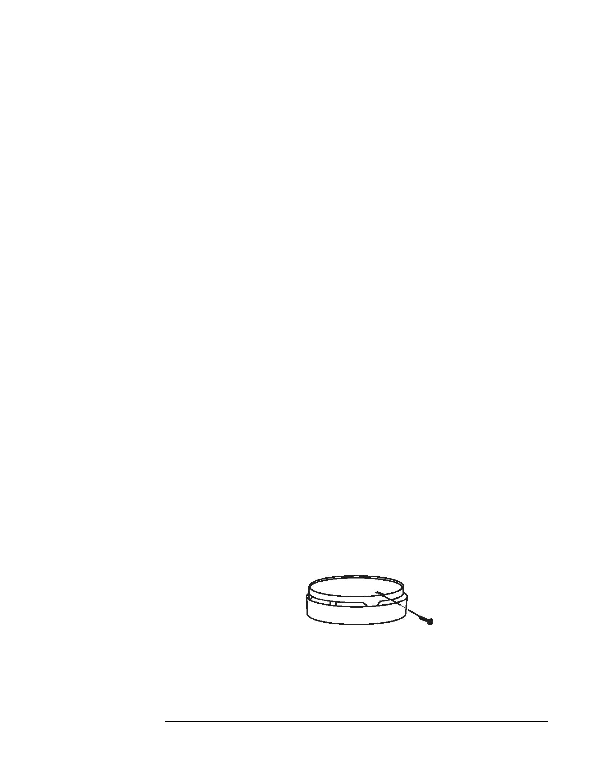
6.7 To make your carbon monoxide alarm tamper resistant, a locking pin has
been provided in the bag with the screws and anchors. Using this pin will
deter children and others from removing the alarm from the mounting plate.
To use the pin insert it into the hole in the side of the alarm after the alarm
has been installed on the mounting plate (See Figure 3). Note the tamper
resist pin will have to be removed in order to change the battery; this can be
done easily with a long nose pliers. Using the long nose pliers pull the pin
out of the hole, it is now possible to remove the alarm from the mounting
plate.
Figure 3: Tamper Resistant Locking Pin
6.8 This box contains two self-adhesive labels. You should write the telephone numbers of the
emergency service provider and a qualified technician in the space provided on the labels. Place
Figure 2: Installation Instructions

one label next to the alarm, and the other label near a source of fresh air where you plan to
gather after the alarm indicates the presence of carbon monoxide.
7.0 ALARM SIGNALS
7.1. NORMAL OPERATION: RED L.E.D. flashes once every 30 seconds,
indicating that the alarm is powered
7.2 ALARM CONDITION: Repeating signal pattern: RED LED turns
"on" for 2 seconds with 4 short beeps and then 5 seconds of silence.
Pushing and holding the test/reset button for 3 seconds will silence the
alarm for about 4 minutes. After 4 minutes, the alarm will once again
sound until the unsafe CO concentration is reduced.
7.3. TROUBLE/SERVICE CONDITION: The alarm self-tests every 10
minutes. The alarm will beep and the RED LED flashes once every 30
seconds if a fault is detected. This is an indication of a malfunction and that
the detector requires immediate servicing or replaced
7.4. LOW BATTERY: RED LED flashes and horn chirp every 30 seconds.
Replace battery when this signal occurs
8.0 MAINTENANCE CLEANING YOUR ALARM:
8.1. Keep your CO alarms clean – use a damp (water only) cloth or vacuum.
8.2. To clean your alarm, remove it from the mounting bracket as outlined in
Figure 2 Step D: Installation/Removal. IF TAMPER RESISTANT PIN
HAS BEEN USED, REFER TO STEP 6.7 UNDER INSTALLATION
INSTRUCTIONS FOR REMOVAL INSTRUCTIONS. (See Figure 3)
8.3 You can clean the interior of your alarm by using your vacuum cleaner
hose and vacuuming through the openings around the perimeter of the
alarm.
8.4 The outside can be wiped with a cloth.
8.5 After cleaning, reinstall your alarm and test your alarm by using the TEST
button.
8.6 Test your detectors weekly and repair or replace them when they no
longer function. As with any electronic product, alarms have a limited life
and alarms that do not work cannot protect you. (See section 10.0)
WARNING: Do not use any household cleaning agents, paints, varnishes

or any other chemical on your COSTAR 9RV-SSO alarm.
9.0 BATTERY REPLACEMENT:
NOTE: IF TAMPER RESISTANT PIN HAS BEEN USED,
REFER TO STEP 6.7 UNDER INSTALLATION
INSTRUCTIONS FOR REMOVAL INSTRUCTIONS. (See
Figure 3)
9.1 To replace the battery remove the alarm from the mounting plate by rotating
the alarm in the direction of the "OFF" arrow on the cover (See Figure 2
Step D). Remove and reinstall the battery in the correct orientation as noted
on the inside of the battery door. The alarm will beep once indicating proper
battery installation. After re-installing the battery, place the alarm on the
mounting plate. Twist the alarm in the direction indicated by the "ON"
arrow on the alarm cover (see Figure 2 step D) until it locks in place.
9.2 The COSTAR 9RV-SSO CO Alarm uses one (1) 9 volt alkaline battery. A
fresh battery should last for one year under normal operating conditions.
They can be purchased anywhere batteries are sold, such as your local
hardware store.
9.3 USE ONLY THE FOLLOWING 9 VOLT BATTERY FOR CO ALARM
REPLACEMENT:
Alkaline type: DURACELL: MN1604
WARNING USE ONLY THE BATTERY SPECIFIED. USE OF
DIFFERENT BATTERIES MAY HAVE A DETRIMENTAL EFFECT
ON THE CO ALARM. THE CONSTANT EXPOSURES TO HIGH OR
LOW TEMPERATURES OR HIGH HUMIDITY MAY REDUCE
BATTERY LIFE. CHECK THE BATTERY MANUFACTURERS
SPECIFICATIONS FOR PROPER OPERATING CONDITIONS.
Note: Most batteries are not rated below -20°C or above
54°C
10.0 PERIODIC ALARM TESTING:
Test the alarm for proper operation by pushing the test button until a short
beep is heard (approximately three seconds). Release the button. The alarm
will then test itself for proper operation and the RED L.E.D. light will flash
4 - 6 times. At completion of the self test, the alarm will sound 2 patterns.
The alarm then resumes normal operation.
WARNING: THIS TEST PROCEDURE WILL TURN OFF THE

APPLIANCE ONCE THE ALARM RESUMES NORMAL
OPERATION, RE-LIGHT APPLIANCE FOLLOWING LIGHTING
INSTRUCTIONS.
WARNING: RESIDENTIAL USE: TEST ALARM OPERATION
AT LEAST ONCE PER WEEK DURING USE OR IF APPLIANCE
WAS TURNED OFF FOR A PERIOD OF TIME.
11.0 SERVICE AND WARRANTY
If after reviewing this manual you feel that your CO Alarm is defective in
any way, do not tamper with the unit. Call your retailer where you
purchased, and they will handle the claim through UNQIUE..

Door Removal & Reversal Instructions
NOTE: The direction in which your refrigerator doors open (door swing) can be
reversed, from left to right or right to left, by moving the door hinges from one side to
the other. Reversing the door swing, should be performed, by a qualified person.
1. Remove top hinge cover
2. Remove top hinge with Philips screwdriver and lift freezer door off of center hinge
and set door aside.
3. Unscrew center hinge with Phillips screwdriver
4. Lift refrigerator door off of bottom hinge and set aside.
5. Remove bottom hinge with Phillips screwdriver.
6. Now remove all plugs and caps from opposite side and place them in the holes
you just remove the screws from.
7. Using a Philips screwdriver fasten the bottom hinge in place using the screws you
previously removed.
8. Place fridge door on bottom hinge, then place middle hinge in top hole of fridge
door and using the Phillips screwdriver, fasten the middle hinge in place using the
screws you previously removed.
9. Now place the freezer door on top of the middle hinge, then place top hinge in
top hole of freezer door and using the Phillips screwdriver, fasten the top hinge in
place using the screws you previously removed.
10. Tighten all screws while making adjustments where necessary to ensure they are
aligned correctly and closing well against the cabinet, this will reduce any excessive
frost build up.
Chapter
7
Temperature Controls
NOTE: Due to the nature of a gas operated absorption fridge, temperatures in
the fridge compartment will drop to freezing even on the lowest setting when
the ambient surrounding the fridge drops to or below 60 F/ 15.0 C overnight
and will freeze your food or drink products. An absorption fridge is always
cooling when operating, as the ambient drops surrounding the appliance so
does the temperate inside the fridge.
COOL DOWN PERIOD
To ensure safe food storage, allow the refrigerator to operate with the doors closed for
at least 8 hours before loading it with food.
REFRIGERATOR CONTROL
NOTE: When first setting the controls or when changing a setting, wait 24 hours for
the temperature to stabilize before making additional changes.
TEMPERATURE ADJUSTMENT
Adjust temperature gradually: move the knob in small increments,
allowing the temperature to stabilize.
For colder temperatures, turn the knob clockwise.
For warmer temperatures, turn the knob towards counter clockwise
Turning the refrigerator control will change temperatures in both compartments.
Remember there is no fan to circulate the air in the refrigerator and freezer
compartments as in an electric fridge. For good circulation, do not block the cooling
fins and try to maintain a temperature of 38 F or 4C in the fridge
NOTE: When first turning refrigerator on, move refrigerator controls to maximum,
which is the recommended initial setting. After 24 hours, adjust the controls as needed.
Chapter
8

Looking Inside
SHELF ADJUSTMENT
Refrigerator shelves are easily adjusted to suit individual needs. Before adjusting the
shelves, remove all food.
Some shelves are removed by just pulling them toward you and sliding them into a
different slot in the fridges cabinet, other shelves are fitted into holes in the sides of the
cabinet and require a small clip to be remove from each side of the shelf in order for
the shelf to be removed and placed into another accommodating hole.
Crispers & Deli Drawers
The crispers, located under the bottom refrigerator shelf, are designed for storing
fruits, vegetables, and other fresh produce. Wash items in clear water and remove
excess water before placing them in the crispers. Items with strong odors or high
moisture content should be wrapped before storing.
Food Storage Ideas
FRESH FOOD STORAGE
The fresh food compartment should be kept between 38° F and 40° F (3.3° C
and 4.4° C) with an optimum temperature of 38° F (3.3°C).
Avoid overcrowding the refrigerator shelves. This reduces the circulation of
air around the food and results in uneven cooling.
Note: The purchase of a remote thermostat is an ideal way to understand how your
appliance functions inside; a sending unit is placed inside your fridge while the
temperature display sits on your kitchen counter. You can keep track of the interior
temperature of the fridge without opening the fridge door.
F
RUITS AND VEGETABLES
Storage in the crisper drawers traps moisture to help preserve the fruit and
vegetable quality for longer time periods.
MEAT
Raw meat and poultry should be wrapped securely so leakage and
contamination of other foods or surfaces does not occur.

FROZEN FOOD STORAGE
The freezer compartment should be kept at 8.6°F (-13°C) at a 77°F
(25°C ) room ambient
A freezer operates most efficiently when it is slowly loaded to 2/3 full.
PACKAGING FOODS FOR FREEZING
To minimize dehydration and quality deterioration, use aluminum foil, freezer
wrap, freezer bags or airtight containers.
Force as much air out of the packages as possible and seal them tightly.
Trapped air can cause food to dry out, change color, and develop an off-
flavour (freezer burn).
Wrap fresh meats and poultry with suitable freezer wrap prior to freezing.
Do not refreeze meat that has completely thawed.
LOADING THE FREEZER
Avoid adding too much warm food to the freezer at one time. This overloads the
freezer, slows the rate of freezing, and can raise the temperature of frozen foods.
Leave a space between the packages, so cold air can circulate freely, allowing food
to freeze as quickly as possible.
Avoid storing hard-to-freeze foods such as ice cream and orange juice on the
freezer door shelves. These foods are best stored in the freezer interior where the
temperature varies less.
Care and Cleaning
Keep your refrigerator and freezer clean to prevent odor build-up. Wipe up any spills
immediately and clean both sections at least twice a year. Never use metallic scouring
pads, brushes, abrasive cleaners or strong alkaline solutions on any surface. Do not
wash any removable parts in a dishwasher.
When moving the refrigerator, pull straight out. You must turn gas off
at source or have adequate flex line to move refrigerator. Do not shift
the refrigerator from side to side as this may tear or gouge the floor
covering and damage the gas supply line.
Damp objects stick to cold metal surfaces. Do not touch refrigerated
surfaces with wet or damp hands.
NOTES:
Do not use razor blades or other sharp instruments, which can scratch
the appliance surface when removing adhesive labels. Any glue left from
tape or labels can be removed with a mixture of warm water and mild
detergent, or, touch the glue residue with the sticky side of tape you have already
removed. Do not remove the certification/serial plate, lighting instructions or
CO warning label.
Parts Diagram and Lists – UGP 6C/8C/10C
Chapter
9
Model UGP 8C
CO-Monitor and Components – all units
UNIQUE ‐UGP6C
Item# Partcode Partname
1 N/A Cabinet
2 DL27501009 Heatsink
3 DL27501005 Driptray
4 DL00009088 Drainagehose
5 DL10001155 Drippan
6 DL22001080 Hingecover
7 DL00003005 Screw
8 DL10001193 Screwcap
9 DL22001079 Tophinge
10 DL22001074 Tophingecover
11 DLUGP6CFRED Freezerdoor
12 DLUGP6CFRID Fridgedoor
13 DL10001020 Washer
14 DL00001191 Screw
15 DL18301079 Middlehinge
16 DL08501152 Washer
17 DL22502213 Bottlerack
18 DL22501145 Freezerbalcony
19 DL22502240 Fridgebalcony
20 DL10001104 Eggtray
21 DL03001003 Icetray
22 DL18301133 Bottleholder
M3
M2
M1
UNIQUE‐UGP6C
Item# Partcode Partname
23 DL22501047 Crisper
24 DL18301080 Bottomhinge
25 DL08501180 Bottomhingepin
26 DL00003018 Springwasher
27 DL00003005 Screw
28 DL27501192 Controlpanel
29
DL27501193
Controllabel
30 DL00013598 Lamp
31 DL00010053 Foot
32 DL00003068 Screw
33 DL14502072 Castor
34 DL22501163 Topshelf
35 DL22501165 Middleshelf
36 DL22501166 Bottomshelf
37
DL18503055 Coolingunit
38 DL27501060 Heater
39 DL00006007 Glasswool
40
DL18501020
Insulationcover
41 DL27501007 Baffle
42 DL18502082 Baffleholder
43 DL00004003 Screw
44 DL00009306 Washer
44‐1 DL10001289 Connector
44‐2 DL10001291 Testvalvebody
44‐3 DL18301172 Screw
44‐4 DL22501186 Injector
45 DL10001180 Burnerassembly
45‐1 DL10001177 Burnerbracket
45‐2 DL10001179 Burnertubesupport
46 DL10001142 Burnertube
47 DL18301042 Burnercover
48 DL10001186 Coverwindow
49 DL10001136 Sealring
50 DL10001113 Nut
51 DL18301122 Pipe
52 DL18301123 Pipe
53 DL10001267 Gasconnector
54 DL00003075 Nut
55 DL10001096 Connectorbracket
56 DL18301374 Electrode
UNIQUE ‐UGP6C
Item# Partcode Partname
57 DL20001077 Piezoignitor
58 DL18301013 Flameindicator
59 DL18301015 Bracket
60 DL22502241 Balconyspacer
61 DL10001114 Connector
62 DL18301115 Thermostat
63 DL18301029 Nut
64 DL10001115 Connector
65 DL18301005 Safetyvalve
66 DL22001180 Connector
67 DL10001349 Thermocouple
68 DL18301012 Thermostatbracket
69 DL28801267 Powercordholder
70 DL10001213 Rotaryswitch
71 DL10001271 Bracket
72 DL18301201 Bracket
73 DL18301033 Knob
74 DL10001327 Connectionwire
75 DL10001328 Connectionwire
76 DL10001350 Connectionwire
77 DL27501137 Frontbottom
77‐1 DL27501138 Rearbottom
78 DL10001116 Connector
79 DL10001145 Spring
80
DL18301034 Button
81 DL10001252 Powercord
82 DL10001056 Groundingwire
83 DL04001634 Lampbox
84 DL27501160 Lampboard
85 DL04001633 Lampcover
86 DL04001632 Lampboxbottom
87 DL22001113 Battery
88 DL27501190 Batteryholder
89 DL27501191 Batterycover
90
DL00013660
Lampswitch
M1 UGP‐9RV‐SSO CODETECTOR9RVSSO
M2 QMP‐INTERRUPTERBLOCK INTERRUPTERBLOCKFOR
CO‐M
ONITOREDFRIDGES
M3
QMP‐36”MOSFET
MOSFETASSY‐FORCO‐MONITOREDMODELS

ELECTRONICIGNITIONSYSTEMCOMPONENTS–NOTSHOWNONDIAGRAMS
N/A DL18301371 BatteryIgnitor
N/A DL22501187 CONNECTIONWIRE
N/A DL18301372 PUSHBUTTONSWITCH
N/A DL10001418 ELECTRODE
N/A DL22501138 CONTROLPANEL
UNIQUE‐UGP8C
Item# Partcode Partname
1 N/A Cabinet
2 DL27501009 Heatsink
3 DL27501005 Driptray
4 DL00009088 Drainagehose
5 DL10001155 Drippan
6 Dl22001080 Hingecover
7 DL00003005 Screw
8 DL10001193 Screwcap
9 DL22001079 Tophinge
10 DL22001074 Tophingecover
11 DLUGP8CFRED Freezerdoor
12 DLUGP8CFRID Fridgedoor
13 DL10001020 Washer
14 DL00001191 Screw
15 DL18301079 Middlehinge
16 DL08501152 Washer
17 DL22502213 Bottlerack
18 DL22501145 Freezerbalcony
19 DL22502240 Fridgebalcony
20 DL10001104 Eggtray
21 DL03001003 Icetray
22 DL18301133 Bottleholder
23 DL22501047 Crisper
24 DL18301080 Bottomhinge
25 DL08501180 Bottomhingepin
26 DL00003018 Springwasher
27 DL00003005 Screw
28 DL27501192 Controlpanel
29 DL27501193 Controllabel
30 DL00013598 Lamp
31 DL00010053 Foot
32 DL00003068 Screw
33 DL14502072 Castor
34 DL22501163 Topshelf
34‐1 DL22501164 Middleshelf
35 DL22501165 Middleshelf
36 DL22501166 Bottomshelf
37 DL22503082 Coolingunit
38 DL27501060 Heater
39 DL00006007 Glasswool

UNIQUE‐UGP8C
Item# Partcode Partname
40 DL22501136 Insulationcover
41 DL27501007 Baffle
42 DL22502227 Baffleholder
43 DL00004003 Screw
44 DL00009306 Washer
44‐1 DL22501185 Connector
44‐2 DL10001291 Testvalvebody
44‐3 DL18301172 Screw
44‐4 DL22501186 Injector
45 DL10001180 Burnerassembly
45‐1 DL10001177 Burnerbracket
45‐2 DL10001179 Burnertubesupport
46 DL10001142 Burnertube
47 DL18301042 Burnercover
48 DL10001186 Coverwindow
49 DL10001136 Sealring
50 DL10001113 Nut
51 DL18301122 Pipe
52 DL18301123 Pipe
53 DL10001267 Gasconnector
54 DL00003075 Nut
55 DL10001096 Connectorbracket
56 DL18301374 Electrode
57 DL20001077 Piezoignitor
58 DL18301013 Flameindicator
59 DL18301015 Bracket
60 DL22502241 Balconyspacer
61 DL10001114 Connector
62 DL18301115 Thermostat
63 DL18301029 Nut
64 DL10001115 Connector
65 DL18301005 Safetyvalve
66 DL22001180 Connector
67 DL10001349 Thermocouple
68 DL18301012 Thermostatbracket
69 DL28801267 Powercordholder
70 DL10001213 Rotaryswitch
71 DL10001271 Bracket
72 DL18301201 Bracket
UNIQUE ‐UGP8C
Item# Partcode Partname
73 DL18301033 Knob
74 DL10001327 Connectionwire
75 DL10001328 Connectionwire
76 DL10001350 Connectionwire
77 DL27501137 Frontbottom
77‐1 DL27501138 Rearbottom
78 DL10001116 Connector
79 DL10001145 Spring
80 DL18301034 Button
81 DL10001252 Powercord
82 DL10001056 Groundingwire
83 DL04001634 Lampbox
84 DL27501160 Lampboard
85 DL04001633 Lampcover
86 DL04001632 Lampbox bottom
87 DL22001113 Battery
88 DL27501190 Batteryholder
89 DL27501191 Batterycover
90 DL00013660 Lampswitch
M1 UGP‐9RV‐SSO CODETECTOR9RVSSO
M2 QMP‐INTERRUPTERBLOCK INTERRUPTERBLOCKFOR
CO‐M
ONITOREDFRIDGES
M3 QMP‐36”MOSFET MOSFETASSY‐FORCO‐MONITOREDMODELS
ELECTRONICIGNITIONSYSTEMCOMPONENTS–NOTSHOWNONDIAGRAMS
N/A DL18301371 BatteryIgnitor
N/A DL22501187 CONNECTIONWIRE
N/A DL18301372 PUSHBUTTONSWITCH
N/A DL10001418 ELECTRODE
N/A DL22501138 CONTROLPANEL
UNIQUE‐UGP10C
Item# Partcode Partname
1 N/A Cabinet
2 DL27501009 Heatsink
3 DL27501005 Driptray
4 DL00009088 Drainagehose
5 DL10001155 Drippan
6 Dl22001080 Hingecover
7 DL00003005 Screw
8 DL10001193 Screwcap
9 DL22001079 Tophinge
10 DL22001074 Tophingecover
11 DLUGP10CFRED Freezerdoor
12 DLUGP10CFRID Fridgedoor
13 DL10001020 Washer
14 DL00001191 Screw
15 DL18301079 Middlehinge
16 DL08501152 Washer
17 DL22502213 Bottlerack
18 DL22501145 Freezerbalcony
19 DL22502240 Fridgebalcony
20 DL10001104 Eggtray
21 DL03001003 Icetray
22 DL18301133 Bottleholder
23 DL22501047 Crisper
24 DL18301080 Bottomhinge
25 DL08501180 Bottomhingepin
26 DL00003018 Springwasher
27 DL00003005 Screw
28 DL27501192 Controlpanel
29
DL27501193
Controllabel
30 DL00013598 Lamp
31 DL00010053 Foot
32 DL00003068 Screw
33 DL14502072 Castor
34
DL27501061 Topshelf
34‐1 DL27501062 Middleshelf
35 DL27501063 Middleshelf
36 DL27501064
Bottomshelf
37
DL22503082
Coolingunit
38 DL27501060 Heater
39 DL00006007 Glasswool

UNIQUE ‐UGP10C
Item# Partcode Partname
40
DL22501136
Insulationcover
41 DL27501007 Baffle
42 DL22502227 Baffleholder
43 DL00004003 Screw
44 DL00009306 Washer
44‐1 DL22501185 Connector
44‐2 DL10001291 Testvalvebody
44‐3 DL18301172 Screw
44‐4 DL18301171 Injector
45 DL10001180 Burnerassembly
45‐1 DL10001177 Burnerbracket
45‐2 DL10001179 Burnertubesupport
46 DL10001142 Burnertube
47 DL18301042 Burnercover
48 DL10001186 Coverwindow
49 DL10001136 Sealring
50 DL10001113 Nut
51 DL18301122 Pipe
52 DL18301123 Pipe
53 DL10001267 Gasconnector
54 DL00003075 Nut
55 DL10001096 Connectorbracket
56 DL18301374 Electrode
57 DL20001077 Piezoignitor
58 DL18301013 Flameindicator
59 DL18301015 Bracket
60 DL22502241 Balconyspacer
61 DL10001114 Connector
62 DL18301115 Thermostat
63 DL18301029 Nut
64 DL10001115 Connector
65 DL18301005 Safetyvalve
66 DL22001180 Connector
67 DL10001349 Thermocouple
68 DL18301012 Thermostatbracket
69 DL28801267 Powercordholder
70 DL10001213 Rotaryswitch
71 DL10001271 Bracket
72 DL18301201 Bracket
UNIQUE ‐UGP10C
Item# Partcode Partname
73 DL18301033 Knob
74 DL10001327 Connectionwire
75 DL10001328 Connectionwire
76 DL10001350 Connectionwire
77 DL27501137 Frontbottom
77‐1 DL27501138 Rearbottom
78 DL10001116 Connector
79 DL10001145 Spring
80
DL18301034 Button
81 DL10001252 Powercord
82 DL10001056 Groundingwire
83 DL04001634 Lampbox
84 DL27501160 Lampboard
85 DL04001633 Lampcover
86 DL04001632 Lampbox bottom
87 DL22001113 Battery
88 DL27501190 Batteryholder
89 DL27501191 Batterycover
90 DL00013660 Lampswitch
M1 UGP‐9RV‐SSO CODETECTOR9RVSSO
M2 QMP‐INTERRUPTERBLOCK INTERRUPTERBLOCKFOR
CO‐M
ONITOREDFRIDGES
M3 QMP‐36”MOSFET MOSFETASSY‐FORCO‐MONITOREDMODELS
ELECTRONICIGNITIONSYSTEMCOMPONENTS–NOTSHOWNONDIAGRAMS
N/A DL18301371 BatteryIgnitor
N/A DL22501187 CONNECTIONWIRE
N/A DL18301372 PUSHBUTTONSWITCH
N/A DL10001418 ELECTRODE
N/A DL22501138 CONTROLPANEL

Warranty
UNIQUE UGP-6C/8C/10C
PROPANE REFRIGERATOR - 3 YEAR LIMITED WARRANTY
(1 year parts – 3 year cooling system)
Unique Gas Products Ltd. warrants that this Unique-6C/8C/10C refrigerator is free from
defects in material and workmanship under normal usage and service under the following
terms:
1. This Warranty is made only to the first purchaser (”original purchaser”) who acquires this
refrigerator for his/her own use and will be honored by Unique Gas Products Ltd. and
by the Seller.
2. Any part of this refrigerator returned to the Seller or Unique Gas Products Ltd, which
upon examination is determined by them to have been defective in material or
workmanship, will at their option be either repaired or replaced under this warranty,
without charge for materials/parts. (Customer is responsible for labour)
3. The obligation to repair or replace defective parts will apply only to parts returned within
one year of the date of purchase and will constitute the Sellers sole obligation under this
Warranty.
The Seller will have no obligation under this warranty with respect to conditions unrelated to the
material or workmanship of this refrigerator. Such unrelated conditions include without
limitation:
a) faulty installation (or venting) and damage resulting therefrom; not installed by Seller
b) the need for normal maintenance of this refrigerator (including the cleaning of the
Burner, Venturi, Orifice, Flue tubes and assurance of proper propane gas pressure);
c) any accidents to or misuse of any part of this refrigerator and any alteration thereof by
anyone other than the Seller or its authorized representative.
This Unique 6C/8C/10C refrigerator must be serviced regularly as outlined in the Owner’s
Manual. Unique Gas Products Ltd. and the seller will not be liable for direct or indirect loss of
foods caused by failure in operation. In case of failure, the owner must provide proof of
purchase, Model, and Serial Number to the Seller or Unique Gas Products Ltd.
“CARRY IN” Warranty due to remote locations, it is the customer's responsibility to bring
items to dealer for review.
Please fill out warranty card within 30 days and mail back for warranty coverage
2245 Wyecroft Road #5
Oakville, ON, Canada, L6L 5L7
Toll Free: 1-877-427-2266
Ph: 905-827-6154 www.UniqueOffGrid.com
Fax: 905-827-2027

LIMITED WARRANTY
COSTAR Model 9RV-SSO
UNIQUE GAS PRODUCTS LTD offers you this limited warranty on your new carbon monoxide alarm,
including all of its component parts except the battery. This limited warranty extends solely to the original
end-user purchaser of this product, provided your purchase was made from an authorized vendor.
Transfer or resale of this product will automatically terminate warranty coverage.
UNIQUE GAS PRODUCTS LTD. warrants the enclosed carbon monoxide alarm to be free from defects in
materials and workmanship under authorized use and service, as specified in the owner's manual, for a
period of six (5) years from the date of manufacture. All replaced items become the property of UNIQUE
GAS PRODUCTS LTD.
UNIQUE GAS PRODUCTS LTD.MAKES NO OTHER WARRANTIES, EXPRESS OR IMPLIED, EXCEPT
AS REQUIRED BY LAW, AND IN NO CASE FOR A DURATION LONGER THAN THAT OF THIS WRITTEN
WARRANTY, EXCEPT AS REQUIRED BY LAW, INCLUDING, BUT NOT LIMITED TO, ANY WARRANTY
OF MERCHANTABILITY OR FITNESS FOR A PARTICULAR PURPOSE OR AGAINST INFRINGEMENT,
OR ANY EXPRESS OR IMPLIED WARRANTY ARISING OUT OF TRADE USAGE OR OUT OF A
COURSE OF DEALING OR COURSE OF PERFORMANCE. UNIQUE GAS PRODUCTS LTD.has not
authorized any other party to extend any other warranties in connection with the sale of the product, and will
not accept responsibility for any statements, representations, or warranties made by any other person.
This limited warranty does not cover: (1) 9 volt alkaline battery; (2) products which have been improperly
installed, repaired, maintained, modified, or which have been subjected to misuse, abuse, accident,
neglect, exposure to fire, water, or excessive changes in climate or temperature, or combined with non-
UNIQUE GAS PRODUCTS LTD.. - approved accessories; (3) physical damage caused from use other
than normal and proper operation or handling, as specified in the owner's manual; (4) cosmetic damage;
(5) products on which warranty stickers or product serial numbers have been removed, altered, or
rendered illegible; (6) the cost of installation, removal or reinstallation.
UNIQUE GAS PRODUCTS LTD.SPECIFICALLY DISCLAIMS LIABILITY FOR ANY AND ALL DIRECT,
INDIRECT, SPECIAL, GENERAL, INCIDENTAL, OR CONSEQUENTIAL DAMAGES, INCLUDING, BUT
NOT LIMITED TO, LOSS OF PROFITS OR ANTICIPATED PROFITS ARISING OUT OF USE OF OR
INABILITY TO USE THE PRODUCT.