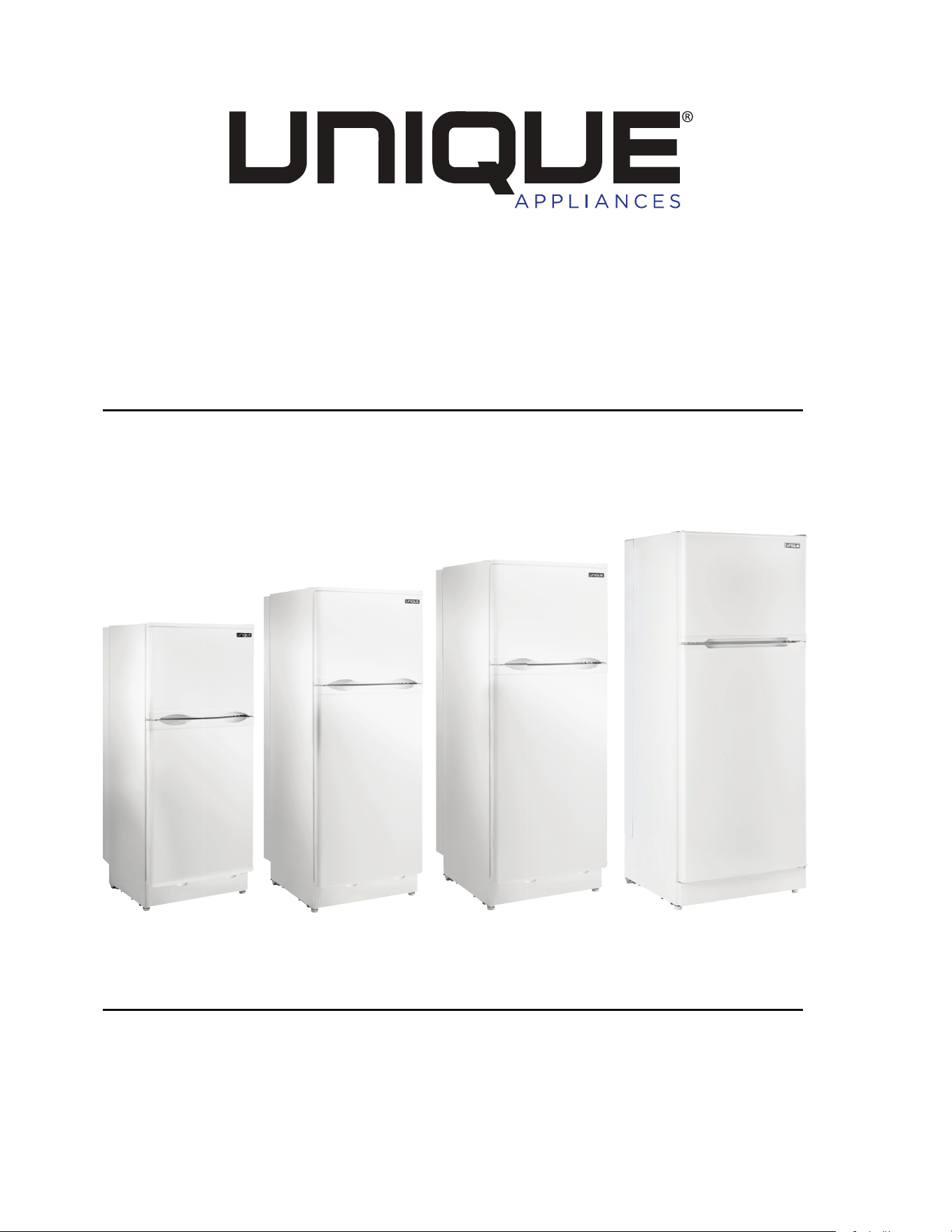
Propane Refrigerator
OWNER”S GUIDE
serial number:
UGP 6C/8C/10C/14C
APR2020V1

UNIQUE UGP-6C/8C/10C/14C
Propane Refrigerator
Installation and Owner’s Manual
WARNING
FIRE OR EXPLOSION HAZARD
If you smell gas:
1. Open windows.
2. Do not attempt to light appliance and make
sure the appliance is in the OFF position.
3. Extinguish any open flame.
4. Do not touch electrical switches.
5. Do not use electronic devices such as cell
phones or landline phones.
6. Evacuate the building or recreational vehicle.
7. Shut off fuel supply at LP tank.
8. Call emergency services.
Failuer to follow these instructions could result in
fire or explosion, which could ause property damage,
personal injury or death.
April 2020
The installation of the appliance must conform with local codes or,
in the absence of local codes, to the national Fuel Gas Code, ANSI Z233.1
and in Canada B149.2 Propane Storage and Handling Code
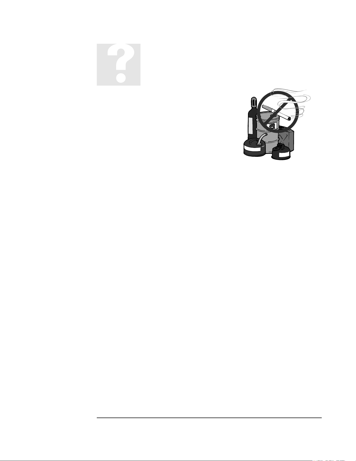
FOR YOUR SAFETY: Do not store or use gasoline or other flammable vapors and
liquids in the vicinity of this unit or any other appliance
WARNING: In Canada, an unvented refrigerator shall only be installed in an area
that is not normally occupied, not used in sleeping quarter sand does not directly
communicate with occupied areas
WARNING: Carbon Monoxide Poisoning may cause death or injury
WARNING: Improper installation, adjustment, alteration, service or maintenance
can cause injury or property damage. Refer to this manual. For assistance or additional
information consult a qualified installer, service agency or the gas supplier.
WARNING
CARBON MONOXIDE POISONING MAY
CAUSE DEATH OR INJURY
When used without adequate combustion
and ventilation air, the refrigerator may
give off excess CARBON MONOXIDE, and
odorless poisonous gas.
This is an unvented gas-fired appliance.
The refrigerator uses air (oxygen) from the
area in which the refrigerator is used.
Adequate combustion and ventilation air
must be provided. Refer to page 5.


NOTICE TO INSTALLER/CUSTOMER
Please read carefully before hook-up!
1. The dwelling must have an adequate air supply and access to fresh air/oxygen in order to operate safely. Propane
fridges/freezers, like any other gas appliance, must have access to fresh air/oxygen. This unvented appliance must not be used
in an airtight application.
2. This refrigerator must be installed by a licensed gas fitter.
3. The propane gas supply pressure regulator must be set at 11” water column.
4. The left side heat shield (facing front of the refrigerator) must be installed. The heat shield is shipped in the refrigerator carton.
5. For safety & efficient temperature
6. Owner’s Manual.
7. For proper and efficient operation the refrigerator must be level, both side to side and front to back (use bubble type level).
8. The Combination Carbon Monoxide (CO) Alarm & Safety Shut-Off must be installed and connected (CM Models only) with the
Alarm mounted as indicated in the Carbon Monoxide Alarm (Monitor) Installation Manual.
NOTE: It is illegal to operate this refrigerator in Canada without the Combination Carbon Monoxide
Alarm & Safety Shut-Off installed, and will void the Canadian Standards Association Certification. Non
compliance will void the Canadian certification and void household/cottage insurance coverage. This
refrigerator vents combustion products directly into the living space. The CO Alarming Device with Safety Shut-Off
has been added to this refrigerator to guard against potentially high levels of Carbon Monoxide, which can kill you.
Once unsafe levels of CO are detected, an alarm will sound and the refrigerator will be shut off.
WARNING: Actuation of this device indicates the presence of unsafe levels of carbon monoxide (CO) which can KILL
YOU. If alarm signal sounds:
a) Immediately move to fresh air --- outdoors or by an open door or window. Check that all persons are accounted for. Do not re-
enter the premises or move away from the open door/window until the emergency services responders have arrived, the
premises have been aired out, and your alarm remains in its normal condition;
b) Call emergency local service telephone number, fire department or 911.
c) The following symptoms may be related to CARBON MONOXIDE POISONING and should be discussed with ALL members of the
household:
Mild Exposure: Headaches, running nose, sore eyes, often described as “flu”-like symptoms;
Medium Exposure: Dizziness, drowsiness, vomiting;
Extreme Exposure: Unconscious, brain damage, death.
d) Read the Instructions for complete Information on Alarms Signals.
9. NOTE: The Combination Carbon Monoxide Alarm & Safety Shut-Off Instructions (CM Model), Owners/Installation Manual are
stored inside the refrigerator.
For Unique Appliances Support, Call Toll Free 1-877-427-2266
10. Regular maintenance of the fridge is critical to prevent unsafe levels of Carbon Monoxide. Before lighting the refrigerator at any
time, clean the flue tube as per the Owner’s Manual & make sure the burner and areas around the burner are free from any lint,
spider webs or any other debris. Please record your appliance maintenance on the SERVICE RECORD label located at the back of
your appliance.
WARNING -- Test the Combination Carbon Monoxide & Safety Shut-Off device operation after the refrigerator has
been in storage, before each startup, and at least once per week during use.
2245 Wyecroft Road, Oakville, Ontario, Canada L6L 5L7 •Tel: 905-827-6154 • Toll Free: 1-877-427-2266 • Fax: 905-827-2027
www.Uniqueappliances.com

MANUFACTURED AND CERTIFIED BY
Unique Appliances
Unique Appliances,
2245 Wyecroft Road
Oakville, Ontario, Canada, L6L 5L7
Ph: 905-827-6154 Toll Free: 1-877-427-2266 Fax: 905-827-2027
www.Uniqueappliances.com
E-mail: info@uniqueappliances.com
“
“
P
P
E
E
R
R
S
S
O
O
N
N
A
A
L
L
S
S
E
E
R
R
V
V
I
I
C
C
E
E
&
&
K
K
N
N
O
O
W
W
L
L
E
E
D
D
G
G
E
E
M
M
A
A
K
K
E
E
S
S
U
U
S
S
U
U
N
N
I
I
Q
Q
U
U
E
E
”
”


Table of Contents
Chapters
Welcome 1
Safety and Warnings 1
Appliance Installation 2
General Operating Instructions 3
How to use the Refrigerator 3
Maintenance & Service 4
Troubleshooting & Suggested Spares 5
Door Reversal and Removal Instructions 6
Temperature Controls, Food Storage and
Cleaning 7
Parts & Warranty 8
Carbon Monoxide Instructions (CM Model) – Instructions are
located inside CO detector packaging that comes with your fridge.


UGP-6C/8C/10C
1
Welcome &
Congratulations
ongratulations on your purchase of a UNIQUE refrigerator!. We are very
proud of our product and we are completely committed to providing you with
the best service possible. Your satisfaction is our #1 priority. Please read this
manual very carefully. It contains valuable information on how to properly
maintain your new gas refrigerator.
We know you will enjoy your new refrigerator and thank you for choosing one of our
Unique Appliances. We hope you will consider us for future purchases.
PLEASE READ AND SAVE THESE INSTRUCTIONS
This manual provides specific operating instructions for your model. Use your
refrigerator only as instructed in this manual. These instructions are not meant to cover
every possible condition and situation that may occur. Common sense and caution
must be practiced when installing, operating and maintaining the appliance
Please record your model and serial # for future reference. This information is found
on your CSA rating/serial plate at the back of your appliance.
PRODUCT REGISTRATION
Please visit our website at https://uniqueappliances.com/product-registration/ to
register your product.
Chapter
1
C
2
Safety and Warnings
If you smell gas
• Open Windows
• Don’t touch electrical switches
• Extinguish any open flame
• Immediately call your gas supplier
For your Safety
• Do not store or use gasoline or other flammable vapors and liquids in the
vicinity of this unit or any other appliance
Warning
• Improper installation, adjustment, alteration, service or maintenance can cause
injury or property damage. Refer to this manual. For assistance or additional
information consult a qualified installer, service agency or the gas supplier.
• This product can produce Carbon Monoxide. Carbon Monoxide has no odour
and can kill you. The burner and flue system must be kept clean. See owner’s
manual for cleaning instructions.
Installation Instructions
• The installation of the appliance must conform with local codes or, in the
absence of local national Fuel Gas Code, ANSI Z233.1 and in Canada B149.2
WARNING
• The California Safe Drinking Water and Toxic Enforcement Act of 1986
(Proposition 65) requires the Governor of California to publish a list of
substances known to the State of California to cause cancer or reproductive
harm. In addition, businesses must warn customers of potential exposure to
such substances. Users of this appliance are hereby warned that the burning
of gas can result in low level exposure to some of the listed substances,
including formaldehyde, benzene, soot and carbon monoxide. This is caused
primarily from the incomplete combustion of natural gas or LP fuel. Properly
adjusted burners will minimize incomplete combustion. Exposure to these
substances can also be minimized by properly venting the burners by opening
a window.
3
Installation
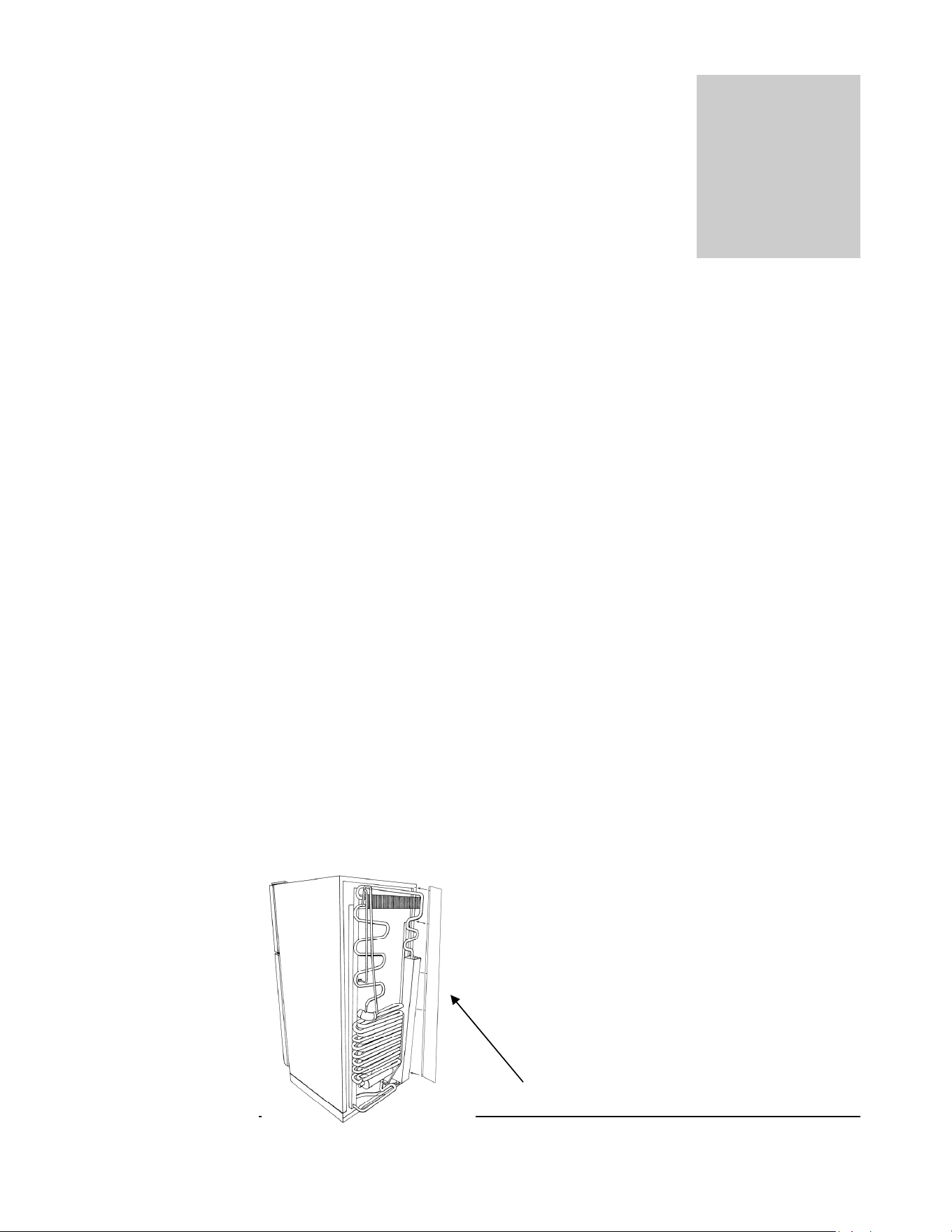
For best performance at high ambient temperatures, there must be free air
circulation over the cooling unit at the rear of the refrigerator.
Ensure that there is a free air space above the refrigerator and that the flue
(chimney) on top of the cabinet is not covered in any way. Do not place the
refrigerator in a space where air circulation is restricted. Follow “clearance”
instructions.
This free-standing refrigerator requires accessibility to the back for servicing the
gas equipment, which can be obtained by using a certified Flexible Metal
Connector to allow the refrigerator to be withdrawn without disrupting the gas
supply. Where a flexible metal connector is used, it must comply with local
authorities and in Canada with the provisions of the current Standard CAN 1-
6.10, Metal Connectors for Gas Appliances. However, if the Local Authorities
require a rigid gas supply connector, the refrigerator should be located with
sufficient space at the back for servicing or, if located against a wall a removable
panel of a minimum size of 16” x 20” should be provided in the wall to allow
access to the rear of the refrigerator. . If you purchased a CM (CO Monitor
model) you must follow instructions that were included with your CO
detector.
Heat Shield
The heat shield must be installed before operating the
appliance. This is a CSA requirement.
Un-wrap the heat shield (located inside the box along
with the appliance). Mount heat shield with the
screws (supplied) to the right side of the fridge.
Chapter
2
Heat Shield
4
A
ir Flow - to release heat trap
6”
6”
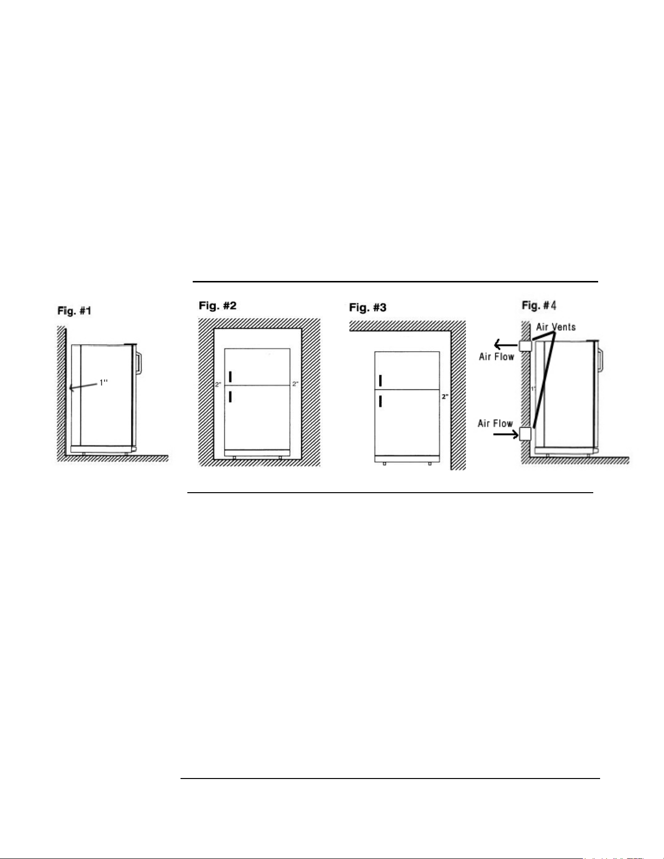
Clearances
Minimum clearances to combustible materials are:
Top – 6”
Sides – 2”
Rear – 1”
as shown in Figures. 1, 2 & 3.
Note: DO NOT install the appliance directly on carpeting. Carpeting must
be removed or protected by a metal or wood panel beneath the appliance,
which extends at least the full width and depth of the appliance.
• Fig. #1 - This is ideal as both top and sides are open
• Fig. #2 – During hot/humid weather this confined area will become very
warm. To reduce heat build-up, we recommend providing an area for two air
vents to circulate the air. One placed 6” off the floor and the other at or above
the appliance top. Cold air return vents with adjustable louvers, works very
well. This will allow hot air to evacuate the area and assist in air flow across the
fins (similar to air passing across a radiator) – See Fig. #4
• Fig. #3 – If this is your opening you only need to stay the diagrammed
distance from the wall and ceiling. There is no need for additional venting.
Gas Connection
Hook-up to the gas supply line: 3/8” SAE (UNF 5/8” - 18) male flare connection. A
backup wrench must be used when tightening gas supply fitting. All completed
5
connections should be checked for leaks with a non-corrosive leak detector and/or
soap and water for a bubble check.
WARNING – DO NOT USE FLAME TO CHECK FOR GAS LEAKS
The gas supply system must incorporate a pressure regulator to maintain a supply
pressure of not more than 12” water column and no less than 11” water column (max
setting).
Make sure the refrigerator and any other high BTU appliances on your line are turned
on when checking the gas pressure. The appliance and its individual shut-off valve
must be disconnected from the gas supply piping system during any pressure testing of
that system at pressures in excess of ½” psig.
In case detailed instructions on the installation and connection of the gas supply are
required, contact your dealer or distributor.
Leveling
Ensure the fridge is level by using a 2ft level. Level the fridge front to back and
left to right using the top of the appliance. There are no leveling legs at the back
of the appliance just at the front; if the back if your floor is uneven you will have
to use shims of some sort to ensure the appliance is level. See the importance of
leveling explained on next page.


6
General Operating Instructions
Importance of Leveling a Refrigerator
The refrigerator must be adjusted to a vertical position in both directions. In an
absorption refrigeration system, ammonia is liquefied in the finned condenser coil at
the top rear of the refrigerator. The liquid ammonia then flows into the evaporator
(inside the freezer section) and is exposed to circulating flow of hydrogen gas, which
causes the ammonia to evaporate, creating a cold condition in the freezer.
When starting this refrigerator for the very first time, the cooling cycle may require up
to 8 hours of running time before the cooling unit is fully operational to begin slowly
loading compartment with cold food from your cooler.
At room temperatures under 60°F (15.5°C), there is a risk that the temperature in the
main compartment will drop below freezing point, even with the thermostat at the
warmest setting. Optimal operating temperatures shall be between 65°F (18°C) and
90°F (32°C). Storage and non-operating temperatures can be between 5°F (-15°C) and
104°F (40°C). The fridge must always be brought up to average room temperature
before starting e.g 65°F (18°C).
The tubing in the evaporator section is specifically sloped to provide a continuous
movement of liquid ammonia, flowing downward by gravity through this section. If
the refrigerator is operated when not level, liquid ammonia will accumulate in sections
of the evaporator tubing. This will slow the circulation of hydrogen and ammonia gas,
or in severe cases, completely block it, resulting in a loss of cooling. Warranty will not
cover recharge/rebuild if caused by not running the fridge level.
This refrigerator operates on LP Gas (Propane) & 110V (Electricity)
Note: After changing an LP tank, or after a long shut off period, the gas line is likely to be filled with
air. You may have to repeat the lighting procedure several times to purge the air out of the gas lines. We
suggest first turning off gas at the control panel, then the tank, this will reduce an air trap in the gas
line.
Chapter
3

7
Gas Operation – for models with electronic ignition
“Start-Up” Procedure
Electronic Ignition (battery)
1. To start the refrigerator, turn the thermostat knob E to the maximum setting, #4.
2. Turn button G to “Gas” position, then push B button in first and hold, proceed to
push in and hold the D button until you see the needle on the flame sensor C
moving from the red into the green area. Release the B button, while continuing to
hold in the D button for an additional 10-15 seconds, now release the D button.
The burner should now stay on indicated by the needle staying in the green area, if
not repeat the lighting instructions above.
3. Adjust the thermostat knob E to desired temperature setting after 8 or more
hours of operation.
4. To change the battery in the electronic ignition, turn the far left knob A to the
left to expose the battery, remove AAA battery and replace with a new one,
positive outwards, replace the knob by turning to the right to close.
Shut Down Procedure – Gas Operation
1. Turn selector knob G to the OFF position
2.
Shut the gas off at the LP-gas supply cylinder when the appliance is not in use.
3. If the refrigerator will not be in operation for a period of weeks, it should be
emptied, defrosted, cleaned and the door left open.
110V Operation
1. Ensure the electrical cord is plugged into a grounded outlet
2. Turn the selector switch G to AC position, AC power indicator F will
illuminate
3. To start the refrigerator, turn the thermostat knob E to the maximum setting.
8
4. Adjust the thermostat knob to desired temperature setting after 8 hours of
operation.
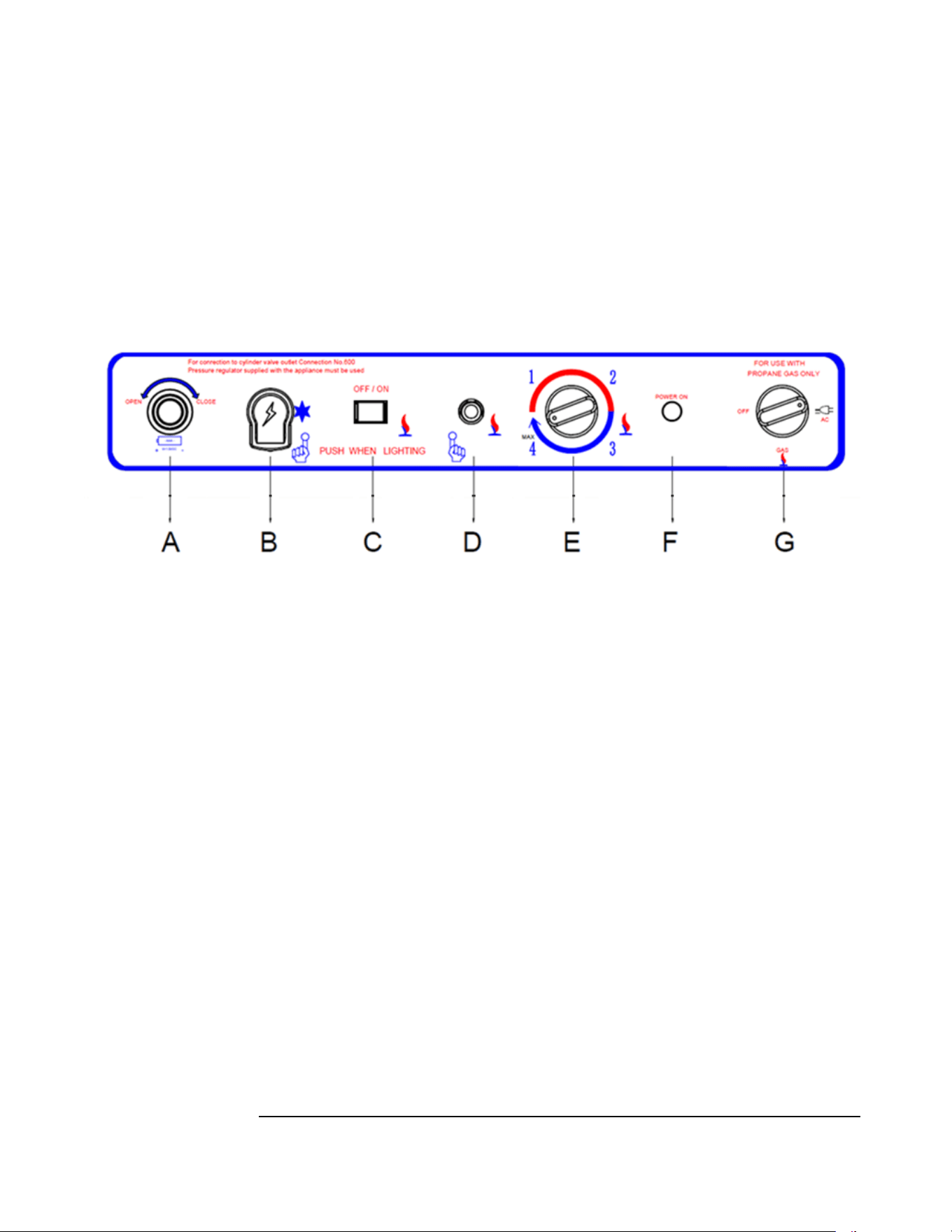
CONTROLS – See Fig. #5 for a description of controls
Thermostat
The refrigerator cooling temperature is controlled by a thermostat that can be adjusted
by turning knob E to different settings to maintain the desired refrigerator
temperature. It also incorporates a safety device which automatically shuts off the
supply of gas if the flame goes out. The electronic ignition discharges sparks onto the
burner when the appropriate button is pushed.
1. “MIN” Setting on the Gas Thermostat: In gas operation, the thermostat closes
its main valve and the burner runs continuously at the bypass rate or pilot flame.
(counter-clockwise turn). If left at the minimum position for an extended period of
time the fridge will defrost.
2. “MAX” Setting of the Thermostat: In gas operation, the thermostat allows the
burner to remain on high flame continuously. (Clockwise turn)
3. The thermostat can be adjusted between “Max” and “Min” (4 or 1) to obtain the
desired fridge temperature.
When the thermostat reaches the set temperature, it will cut the burner back to bypass
operation other than max and min setting.
Figur
e
. #5
9
The setting of the thermostat is critical and we recommend it be adjusted to maintain a
dry frost on the cooling fins (approx. 38° Fahrenheit or 3° Celsius). Adjust the
thermostat knob closer to “Max” (clockwise) when the outside temperature rises.
NOTE: When first turning the refrigerator on, move refrigerator controls to
maximum, which is the recommended initial setting. After 24 hours, adjust the controls
as needed.
How to Use the Refrigerator
FOOD STORAGE COMPARTMENT
The food storage compartment is completely closed and unventilated, which is
necessary to maintain the required low temperature for food storage. The coldest areas
in the refrigerator are under the cooling fins and at the bottom of the refrigerator. The
warmer areas are on the upper door shelves. This should be considered when placing
different types of food in the refrigerator.
FROZEN FOOD STORAGE COMPARTMENT
Quick frozen soft fruits and ice cream should be placed in the coldest part of the
compartment which is at the bottom. Frozen vegetables may be stored in any part of
the compartment.
This compartment is not designed for deep or quick freezing of food. Meat or fish,
whether raw or prepared, can be stored in the frozen food storage compartment
provided they are pre-cooled in the refrigerator. To prevent food from drying out,
keep it in covered dishes, containers, plastic bags or wrapped in aluminum foil.
Defrosting
Frost will gradually accumulate inside the refrigerator and freezer surfaces. It must not
be not allowed to grow too thick as it acts as an insulator and adversely affects the
refrigerator performance. Check the formation of frost every couple of weeks and
when it exceeds 1/2” thick or more defrost the refrigerator.
Shut off and empty the refrigerator, leaving the fridge and the freezer doors open.
Defrosting time can be reduced by filling the ice tray with hot water and placing it in
the freezer compartment. You can also open the doors without shutting off the
appliance to defrost the fridge; the process will just be a bit slower.
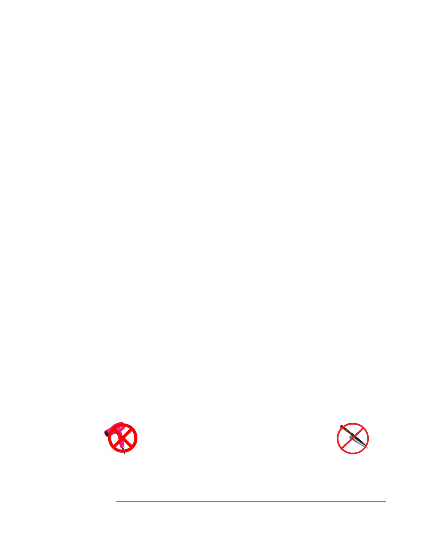
DO NOT USE A HOT AIR BLOWER AS PERMANENT
DAMAGE COULD RESULT
. DO NOT USE A KNIFE, AN ICE
PICK
, OR ANY OTHER SHARP TOOLS TO REMOVE FROST
FROM THE FREEZER COMPARTMENT
.
10
FRIDGE SECTION
Inside the refrigerator compartment, the defrost water runs from a collector channel to
a drip tray/cup at the rear of the refrigerator where it normally evaporates. If heavy
frost has built up on the cooling fins creating a lot of defrost water. Be aware your
water reservoir may overflow. We suggest you inspect reservoir before/after
cycle.
FREEZER SECTION
This area must be wiped down with cloths to remove water after defrosting; there is no
drain for this compartment
When all frost is melted in the freezer compartment & interior of the refrigerator it
should be wiped up with a clean cloth. Replace all food and set the thermostat to your
desired setting.
Cleaning
Cleaning the refrigerator is usually done after it is defrosted or put into storage. To
clean the interior liner of the refrigerator, use lukewarm weak soda solution. Use only
warm water to clean the finned evaporator, gasket, ice trays and shelves.
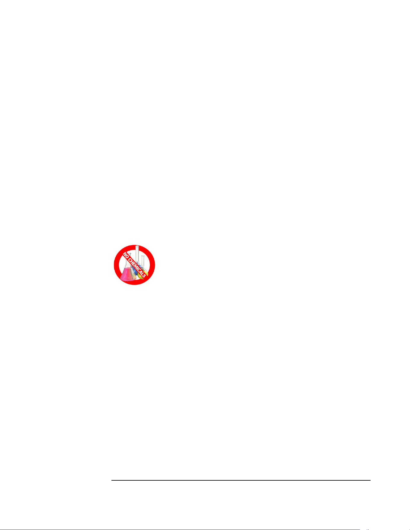
Never use strong chemicals or abrasives to clean these parts as the
protective surfaces will be damaged. It is important to always keep the
refrigerator clean. Dishwasher detergent is recommended
Inside Light
The interior light turns on when the door is open. The light uses four AA batteries
located at the back of the appliance.
To change the batteries, use the following procedure:
1. Go to the back of the appliance and pop off black cover.
2. Remove and replace the 4 x AA batteries.
3. Pop the black cover, back on.
4. The light will come on when the fridge door is open, and will shut off when
the fridge door is closed by a switch located at the upper right-hand side of the
inner portion of the fridge. You can check its operation by manually pressing
and releasing the switch.

11
Shut Down Procedure
A. Turn gas valve knob to the “off” position
B. If the refrigerator will not be in operation for a period of weeks, it should be
emptied, defrosted, cleaned and the doors left open. The ice tray should also be
dried and kept outside the cabinet, also turn off gas at the main supply source.

12
Maintenance & Service
The user should be aware of service that must be done on a regular schedule to keep
the refrigerator operating properly. Installation must be by a licensed gas fitter in
accordance with local codes or in the absence of local national Fuel Gas Code, ANSI
Z233.1 and in Canada B149.2 Propane Storage and Handling Code (latest edition).
REFRIGERATOR REMOVAL and PERIODIC MAINTENANCE
Before working on the refrigerator, shut off the gas supply. Disconnect the gas supply
line at the rear of the refrigerator. Always use a back-up wrench when loosening and
tightening this connection. Cap the gas supply line and remove the refrigerator.
Replacement is the reverse of removal. Check all connections for gas leaks.
Refer to Chapter 2 - Installation
To keep your refrigerator operating effectively and safely, periodic inspection and
cleaning of several components is recommended once or twice a year, sometimes more
often depending on the environment.
• It's important to keep the area at the back of the refrigerator clean. Clean the coils
on the back of the refrigerator. Use a soft bristled brush to dust off
the coils.
Note:
The following maintenance is required at least once
or twice a year at least.
• Check all connectors in the complete refrigerator LP gas system for gas leaks.
The LP gas supply must be turned on. Apply a non-corrosive bubble solution
to all LP connections. The appearance of bubbles indicates a leak and should
be repaired immediately by a qualified serviceman.
W
ARNING – DO NOT USE FLAME TO CHECK FOR GAS
LEAKS
Chapter
4
13
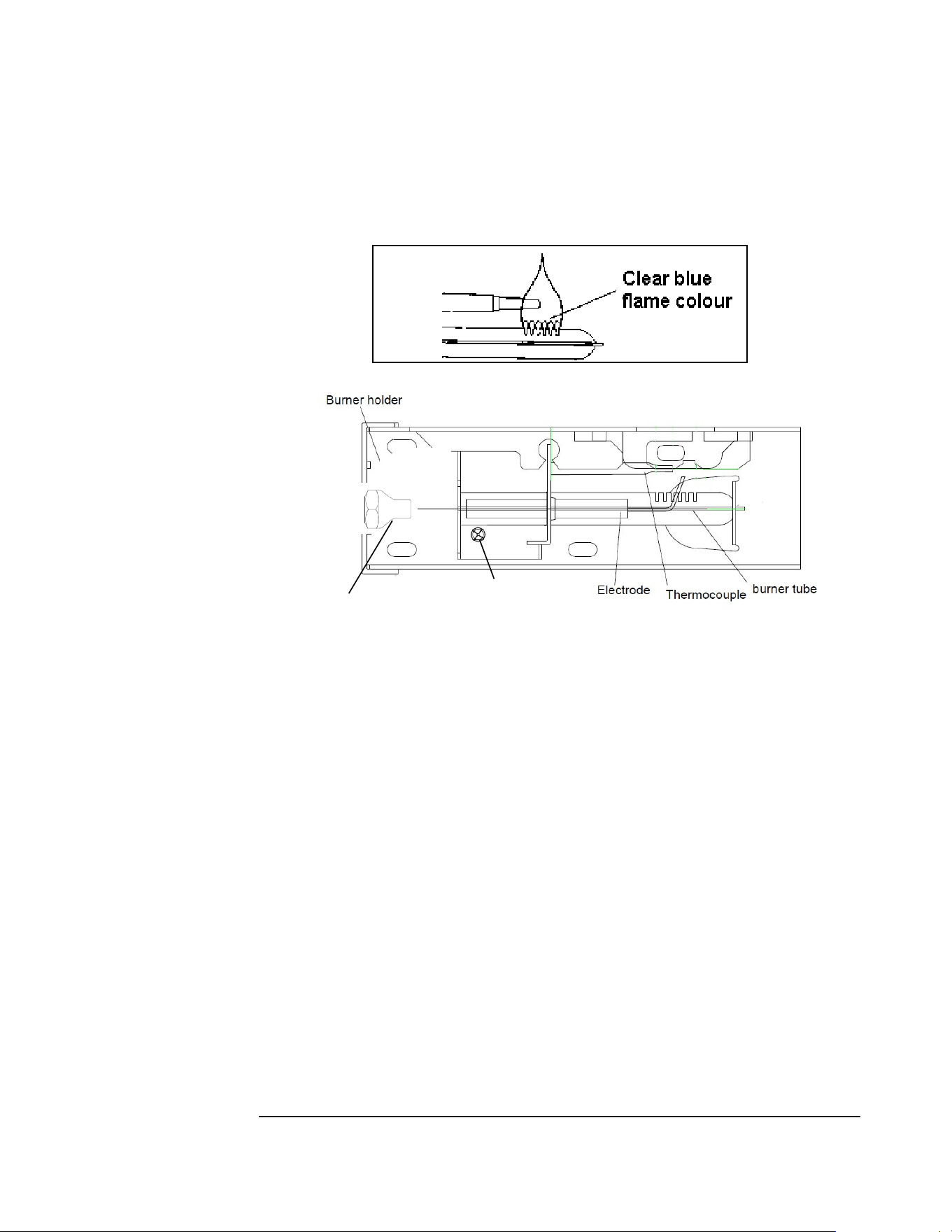
Check burner flame for proper appearance. The flame should be light blue with no
yellow at the tip. See figure #6
• The LP gas pressure should be checked and the main regulator readjusted if
pressure is incorrect. The correct operating pressure is 11” W.C. (water
column).
• Inspect the flue baffle, it should be clean and free of soot. Any soot formation
indicates improper functioning of the burner. The flue and burner both
require cleaning in the following manner:
o
Remove cover from the burner housing.
o
Remove the burner by removing the burner mounting screw
o
Remove the wire and flue baffle from the top of flue tube. Clean the
flue from the top using a flue brush and be sure to cover the burner
if remaining intact to eliminate dirt falling into the burner. Blowing
compressed air into the flue should clean out soot and scale. Replace
the flue baffle.
o
Clean burner tube with compressed air, check for fluff or spider webs.
o
Before removing burner orifice, clean burner area of any soot, scale or
dirt. Remove the orifice/burner jet and soak it in alcohol (isopropyl
alcohol or thinners) and blow it out with compressed air. Re-install
and tighten burner orifice.
o Replace burner
Fig. #6
Fig. #7
Burner Mounting Screw
Burner Jet/Orifice
14
Warning - DO NOT use a pin or wire when
cleaning the burner orifice as damage can occur to
the precision opening. This can cause damage to
the refrigerator or create a fire hazard. It will also
create extremely dangerous levels of carbon
monoxide.
o The inlet & outlet gas fittings on the refrigerator need to be checked
for leaks. Apply a non-corrosive bubble solution to the fittings and
observe for leaks. The safety valve will not allow gas pressure to any
connections between it and the burner orifice. These fittings must be
checked while burner is in operation (gas flow will be present between
safety valve and burner head).
WARNING – The gas button D (Fig. #5) must be
manually depressed to allow gas pressure to flow to the
burner orifice. Be sure to apply the leak check solution
before depressing the safety shut–off. DO NOT allow
any open flame, sparks, smoking, etc. in the area of the
test. DO NOT depress safety shut-off for over 30 seconds.
o If a leak occurs, then allow ten minutes to dissipate from the burner
area. Fix leak then light the burner according to the instructions under
GENERAL OPERATING INSTRUCTIONS – GAS OPERATION, CHAPTER 3.


15
TROUBLESHOOTING INSTRUCTIONS &
SUGGESTED SPARE PARTS TO KEEP ON HAND
REFRIGERATOR DOES NOT COOL, CHECK LIKELY CAUSES:
1.
Burner orifice clogged. Clean. See section Maintenance & Service, CHAPTER 4,
2.
Check to ensure refrigerator is level – (left to right and front to back).
3.
Restriction on airflow across cooling unit.
4.
Heavy frost build-up on evaporator fins. Defrost.
5.
Flue baffle not inserted properly in flue tube.
6.
Improperly set thermostat. See paragraph on the thermostat. In hot weather or
heavy use the setting should be closer to “Max” than usual.
7.
Burner dirty. Clean. See Section MAINTENANCE & SERVICE, CHAPTER 4,
PERIODIC MAINTENANCE
8.
LP gas pressure low at the burner. Regulator pressure must not drop below 11
inches W.C (water column). CHAPTER 2, GAS CONNECTION
9.
Burner not located properly under the flue tube. Relocate; flame must be directly
into the flue
10.
Burner damaged. Replace.
11.
Odours and fumes
• Dislocated burner
• Damaged Burner
• Dirty orifice
• Dirty flue tube – CHAPTER 4.
Chapter
5

16
Spare Parts
The following is a list of commonly used parts which are available:
• Burner orifice
• Burner
• Electrode with wire
• Thermocouple
• Safety valve & Thermostat
• Baffle
Contact your dealer or an authorized service center for parts and repairs as needed.
Quote Model & Serial # - See CSA rating/serial plate at the back of your appliance.

17
Door Removal & Reversal Instructions
NOTE: The direction in which your refrigerator doors open (door swing) can be
reversed, from left to right or right to left, by moving the door hinges from one side to
the other. Reversing the door swing should be performed by a qualified person.
1. Remove top hinge cover.
2. Remove top hinge with Philips screwdriver and lift freezer door off of center hinge
and set door aside.
3. Unscrew center hinge with Phillips screwdriver.
4. Lift refrigerator door off of bottom hinge and set aside.
5. Remove bottom hinge with Phillips screwdriver.
6. Now remove all plugs and caps from opposite side and place them in the holes
you just remove the screws from.
7. Using a Philips screwdriver fasten the bottom hinge in place using the screws you
previously removed.
8. Place fridge door on bottom hinge, then place middle hinge in top hole of fridge
door and using the Phillips screwdriver, fasten the middle hinge in place using the
screws you previously removed.
9. Now place the freezer door on top of the middle hinge, then place top hinge in
top hole of the freezer door and using the Phillips screwdriver, fasten the top hinge
in place using the screws you previously removed.
10. Tighten all screws while making adjustments where necessary to ensure they are
aligned correctly and closing well against the cabinet, this will reduce any excessive
frost build up.
Chapter
6

18
Temperature Controls
NOTE: Due to the nature of a gas operated absorption fridge, temperatures in the
fridge compartment will drop to freezing even on the lowest setting when the ambient
temperature surrounding the fridge drops to or below 60° F/ 15.0° C overnight and
will freeze your food or drink products. An absorption fridge is always cooling when
operating, as the ambient drops surrounding the appliance so does the temperature
inside the fridge.
COOL DOWN PERIOD
To ensure safe food storage, allow the refrigerator to operate with the doors closed for
at least 8 hours before loading it with food.
REFRIGERATOR CONTROL
NOTE: When first setting the controls or when changing a setting, wait 24 hours for
the temperature to stabilize before making additional changes.
TEMPERATURE ADJUSTMENT
• Adjust temperature gradually: move the knob in small increments,
allowing the temperature to stabilize.
• For colder temperatures, turn the knob clockwise.
• For warmer temperatures, turn the knob towards counter-clockwise
Turning the refrigerator control will change temperatures in both compartments.
Remember there is no fan to circulate the air in the refrigerator and freezer
compartments as in an electric fridge. For good circulation, do not block the cooling
fins and try to maintain a temperature of 38° F or 4°C in the fridge
NOTE: When first turning the refrigerator on, move refrigerator controls to
maximum, which is the recommended initial setting. After 24 hours, adjust the controls
as needed.
Chapter
7

19
Looking Inside
SHELF ADJUSTMENT
Refrigerator shelves are easily adjusted to suit individual needs. Before adjusting the
shelves, remove all food.
Crispers & Deli Drawers
The crispers, located under the bottom refrigerator shelf, are designed for storing
fruits, vegetables, and other fresh produce. Wash items in clear water and remove
excess water before placing them in the crispers. Items with strong odors or high
moisture content should be wrapped before storing. UGP-14C does not apply as it
has a wire basket for the crisper drawer
Food Storage Ideas
FRESH FOOD STORAGE
• The fresh food compartment should be kept between 38° F and 40° F (3.3° C
and 4.4° C) with an optimum temperature of 38° F (3.3°C).
• Avoid overcrowding the refrigerator shelves. This reduces the circulation of
air around the food and results in uneven cooling.
Note: The purchase of a remote thermostat is an ideal way to understand how your
appliance functions inside; a sending unit is placed inside your fridge while the
temperature display sits on your kitchen counter. You can keep track of the interior
temperature of the fridge without opening the fridge door.
F
RUITS AND VEGETABLES
• Storage in the crisper drawers traps moisture to help preserve the fruit and
vegetable quality for longer time periods.
MEAT
• Raw meat and poultry should be wrapped securely so leakage and
contamination of other foods or surfaces does not occur.
FROZEN FOOD STORAGE
• The freezer compartment should be kept at 8.6°F (-13°C) at a 77°F
(25°C ) room ambient

20
•
A freezer operates most efficiently when it is slowly loaded to 2/3 full.
PACKAGING FOODS FOR FREEZING
• To minimize dehydration and quality deterioration, use aluminum foil, freezer
wrap, freezer bags or airtight containers.
• Force as much air out of the packages as possible and seal them tightly.
Trapped air can cause food to dry out, change color, and develop an off-
flavour (freezer burn).
• Wrap fresh meats and poultry with suitable freezer wrap prior to freezing.
• Do not refreeze meat that has completely thawed.
LOADING THE FREEZER
• Avoid adding too much warm food to the freezer at one time. This overloads the
freezer, slows the rate of freezing, and can raise the temperature of frozen foods.
• Leave a space between the packages, so cold air can circulate freely, allowing food
to freeze as quickly as possible.
• Avoid storing hard-to-freeze foods such as ice cream and orange juice on the
freezer door shelves. These foods are best stored in the freezer interior where the
temperature varies less.
Care and Cleaning
Keep your refrigerator and freezer clean to prevent odor build-up. Wipe up any spills
immediately and clean both sections at least twice a year. Never use metallic scouring
pads, brushes, abrasive cleaners or strong alkaline solutions on any surface. Do not
wash any removable parts in a dishwasher.
• When moving the refrigerator, pull straight out. You must turn gas off
at the source or have adequate flex line to move the refrigerator. Do not
shift the refrigerator from side to side as this may tear or gouge the
floor covering and damage the gas supply line.
• Damp objects stick to cold metal surfaces. Do not touch refrigerated
surfaces with wet or damp hands.

21
NOTES:
Do not use razor blades or other sharp instruments, which can scratch the appliance
surface when removing adhesive labels. Any glue left from tape or labels can be
removed with a mixture of warm water and mild detergent, or, touch the glue residue
with the sticky side of tape you have already removed. Do not remove the
certification/serial plate, lighting instructions or CO warning label.
22
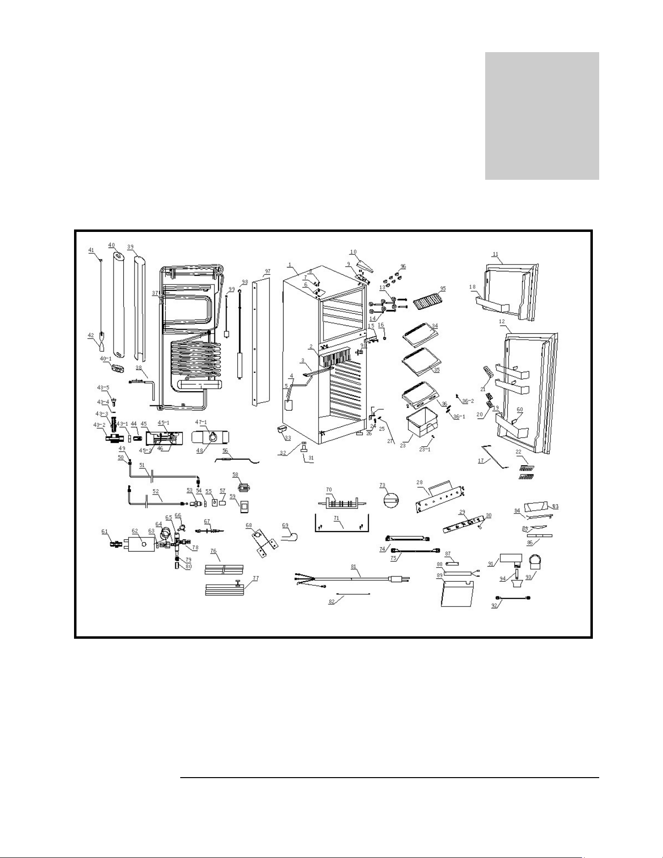
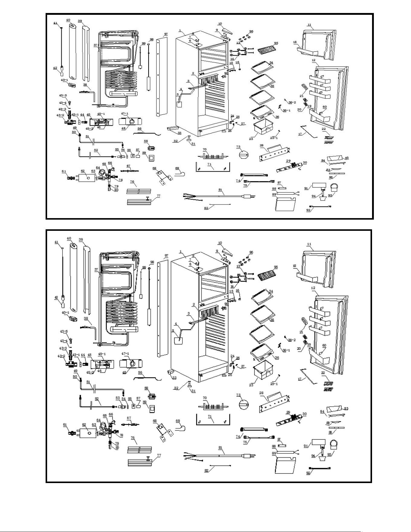
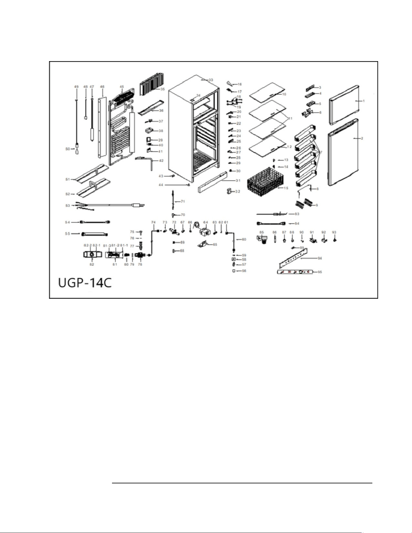
Parts Diagram and Lists – UGP 6C/8C/10C/14C
Chapter
8
UGP-6C
23
UGP-8C
UGP-10C
24
25
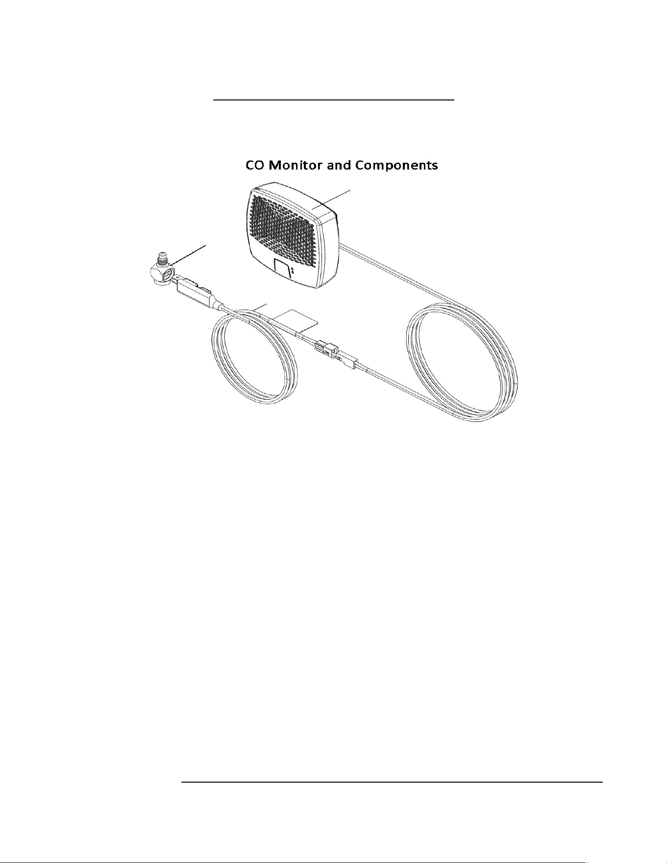
CO-Monitor and Components – all units
M1
M2
M3
26
UNIQUE – UGP 6C
No. Item Code
1 Cabinet N/A
2 Heat sink UGP-DL22502524
3 Drip tray UGP-DL22501294
4 Drainage hose UGP-DL00009088
5 Drip pan UGP-DL10001155
6 Hinge cover UGP-DL22001080
7 Screw UGP-DL00003005
8 Screw cap UGP-DL10001193
9 Top hinge UGP-DL22001079
10 Top hinge cover UGP-DL22001074
11 Freezer door - White UGP-DL90000008
11 Freezer door – Black UGP-DL90000009
12 Fridge door – White UGP-DL90000012
12 Fridge door – Black UGP-DL90000013
13 Washer UGP-DL22502504
14 Screw UGP-DL27501364
15 Middle hinge UGP-DL27501359
16 Washer UGP-DL08501152
17 Bottle rack UGP-DL22502213
18 Freezer balcony UGP-DL22501145
19 Fridge balcony UGP-DL22502240
20 Egg tray UGP-DL10001104
21 Ice tray UGP-DL03001003
22 Bottle holder UGP-DL18301133
23 Crisper UGP-DL22501289
23-1 Top wearing plate UGP-DL27501311
24 Bottom hinge UGP-DL18301080
25 Bottom hinge pin UGP-DL08501180
26 Spring washer UGP-DL00003018
27 Screw UGP-DL00003005
28 Control panel UGP-DL27501358
29 Control label UGP-DL27501241
30 Lamp UGP-DL00013598
31 Foot UGP-DL00010053
32 Screw UGP-DL00003068
33 Castor UGP-DL14502072
27
No. Item Code
34 Top shelf UGP-DL22501296
35 Middle shelf UGP-DL22501297
36 Bottom shelf UGP-DL27501306
36-1 Ventilation hood UGP-DL27501310
36-2 Bottom wearing plate UGP-DL27501312
37 Cooling unit UGP-DL22503082
38 Heater UGP-DL27501293
39 Glass wool UGP-DL00006007
40 Insulation cover UGP-DL22501136
40-1 cover cap UGP-DL22501173
41 Baffle UGP-DL27501007
42 Baffle holder UGP-DL18502082
43 Checkpoint assembly UGP-DL27501365
43-1 Screw UGP-DL10001474
43-2 Test valve body UGP-DL10001498
43-3 Connector UGP-DL10001501
43-4 Washer UGP-DL00009306
43-5 Screw UGP-DL22501206
44 Injector UGP-DL10001470
45 Burner assembly UGP-DL10001496
45-1 Burner bracket UGP-DL22502507
45-2 Burner tube support UGP-DL10001476
46 Burner tube UGP-DL10001142
47 Burner cover assembly UGP-DL22502506
47-1 Burner cover UGP-DL22502508
48 Cover window UGP-DL10001186
49 Seal ring UGP-DL10001136
50 Nut UGP-DL10001113
51 Outlet Gas Pipe UGP-DL22501300
52 Inlet Gas Pipe UGP-DL22501303
53 Gas connector UGP-DL10001267
54 Nut UGP-DL00003075
55 Connector bracket UGP-DL10001096
56 Electrode UGP-DL27501257
57 Gas inlet cap UGP-DL22001160
58 Flame indicator UGP-DL18301013
59 Bracket UGP-DL27501355

28
No. Item Code
60 Balcony spacer UGP-DL22502241
61 Connector UGP-DL10001114
62 Thermostat UGP-DL18301115
63 Nut UGP-DL18301029
64 Connector UGP-DL10001115
65 Safety valve UGP-DL18301005
66 Connector UGP-DL22001180
67 Thermocouple UGP-DL10001349
68 Thermostat bracket UGP-DL18301012
69 Power cord holder UGP-DL28801267
70 Rotary switch UGP-DL10001213
71 Bracket UGP-DL10001271
73 Knob UGP-DL27501362
74 Thermostat Wire UGP-DL27501292
75 Thermocouple Wire UGP-DL10001350
76 Front bottom UGP-DL27501328
77 Rear bottom UGP-DL27501329
78 Connector UGP-DL10001116
79 Spring UGP-DL10001145
80 Button UGP-DL18301034
81 Power cord UGP-DL10001252
82 Grounding wire UGP-DL10001056
83 Lamp box UGP-DL04001634
84 Lamp board UGP-DL27501160
85 Lamp cover UGP-DL04001633
86 Lamp box bottom UGP-DL04001632
87 Battery UGP-DL22001113
88 Battery holder UGP-DL27501190
89 Battery cover UGP-DL27501342
90 Lamp switch UGP-DL00013660
91 Battery ignitor UGP-DL18301371
92 Pulse Ignition Wire UGP-DL22501187
93 Push button switch UGP-DL18301372
94 Battery UGP-DL00013681
29
No. Item Code
95 freezer shelf UGP-DL222501280
96 Screw cover UGP-DL27501363
97 Heat Shield UGP-DL18501044
98 Big brush UGP-DL22001096
99 Small brush UGP-DL27501318
M1
UGP-9RV-SSO-C CO Detector 9RV SSO-C
M2
QMP-Interrupter Block Interrupter Block for CO-Monitored fridges
M3
QMP-Mosfet-C Mosfet Assembly - for CO-Monitored Models
30
UNIQUE UGP 8C Parts List
No. Item Code
1 Cabinet N/A
2 Heat sink UGP-DL22502524
3 Drip tray UGP-DL22501294
4 Drainage hose UGP-DL00009088
5 Drip pan UGP-DL10001155
6 Hinge cover UGP-DL22001080
7 Screw UGP-DL00003005
8 Screw cap UGP-DL10001193
9 Top hinge UGP-DL22001079
10 Top hinge cover UGP-DL22001074
11 Freezer door - White UGP-DL90000008
11 Freezer door – Black UGP-DL90000009
11 Freezer door - Stainless UGP-DL90000010
12 Fridge door – White UGP-DL90000005
12 Fridge door – Black UGP-DL90000006
12 Fridge Door - Stainless UGP-DL90000007
13 Washer UGP-DL22502504
14 Screw UGP-DL27501364
15 Middle hinge UGP-DL27501359
16 Washer UGP-DL08501152
17 Bottle rack UGP-DL22502213
18 Freezer balcony UGP-DL22501145
19 Fridge balcony UGP-DL22502240
20 Egg tray UGP-DL10001104
21 Ice tray UGP-DL03001003
22 Bottle holder UGP-DL18301133
23 Crisper UGP-DL22501289
23-1 Top wearing plate UGP-DL27501311
24 Bottom hinge UGP-DL18301080
25 Bottom hinge pin UGP-DL08501180
26 Spring washer UGP-DL00003018
27 Screw UGP-DL00003005
28 Control panel UGP-DL27501358
29 Control label UGP-DL27501241
30 Lamp UGP-DL00013598
31 Foot UGP-DL00010053

31
No. Item Code
32 Screw UGP-DL00003068
33 Castor UGP-DL14502072
34 Top shelf UGP-DL22501296
35 Middle shelf UGP-DL22501297
36 Bottom shelf UGP-DL27501306
36-1 Ventilation hood UGP-DL27501310
36-2 Bottom wearing plate UGP-DL27501312
37 Cooling unit UGP-DL22503082
38 Heater UGP-DL27501293
39 Glass wool UGP-DL00006007
40 Insulation cover UGP-DL22501136
40-1 cover cap UGP-DL22501173
41 Baffle UGP-DL27501007
42 Baffle holder UGP-DL22502227
43 Checkpoint assembly UGP-DL27501365
43-1 Screw UGP-DL10001474
43-2 Test valve body UGP-DL10001498
43-3 Connector UGP-DL10001501
43-4 Washer UGP-DL00009306
43-5 Screw UGP-DL22501206
44 Injector UGP-DL10001470
45 Burner assembly UGP-DL10001496
45-1 Burner bracket UGP-DL22502507
45-2 Burner tube support UGP-DL10001476
46 Burner tube UGP-DL10001142
47 Burner cover assembly UGP-DL22502506
47-1 Burner cover UGP-DL22502508
48 Cover window UGP-DL10001186
49 Seal ring UGP-DL10001136
50 Nut UGP-DL10001113
51 Outlet Gas Pipe UGP-DL22501300
52 Inlet Gas Pipe UGP-DL22501303
53 Gas connector UGP-DL10001267
54 Nut UGP-DL00003075
55 Connector bracket UGP-DL10001096
56 Electrode UGP-DL27501257
57 Gas inlet cap UGP-DL22001160
32
No. Item Code
58 Flame indicator UGP-DL18301013
59 Bracket UGP-DL27501355
60 Balcony spacer UGP-DL22502241
61 Connector UGP-DL10001114
62 Thermostat UGP-DL18301115
63 Nut UGP-DL18301029
64 Connector UGP-DL10001115
65 Safety valve UGP-DL18301005
66 Connector UGP-DL22001180
67 Thermocouple UGP-DL10001349
68 Thermostat bracket UGP-DL18301012
69 Power cord holder UGP-DL28801267
70 Rotary switch UGP-DL10001213
71 Bracket UGP-DL10001271
73 Knob UGP-DL27501362
74 Thermostat Wire UGP-DL27501292
75 Thermocouple Wire UGP-DL10001350
76 Front bottom UGP-DL27501328
77 Rear bottom UGP-DL27501329
78 Connector UGP-DL10001116
79 Spring UGP-DL10001145
80 Button UGP-DL18301034
81 Power cord UGP-DL10001252
82 Grounding wire UGP-DL10001056
83 Lamp box UGP-DL04001634
84 Lamp board UGP-DL27501160
85 Lamp cover UGP-DL04001633
86 Lamp box bottom UGP-DL04001632
87 Battery UGP-DL22001113
88 Battery holder UGP-DL27501190
89 Battery cover UGP-DL27501342
90 Lamp switch UGP-DL00013660
91 Battery ignitor UGP-DL18301371
92 Pulse Ignition Wire UGP-DL22501187
93 Push button switch UGP-DL18301372
94 Battery UGP-DL00013681
95 Freezer shelf UGP-DL22501280
33
No. Item Code
96 Screw cover UGP-DL27501363
97 Heat Shield UGP-DL22501209
98 Big brush UGP-DL22001096
99 Small brush UGP-DL27501318
M1
UGP-9RV-SSO-C CO Detector 9RV SSO-C
M2
QMP-Interrupter Block Interrupter Block for CO-Monitored fridges
M3
QMP-Mosfet-C Mosfet Assembly - for CO-Monitored Models
34
UNIQUE – UGP 10C Parts List
No. Item Code
1 Cabinet N/A
2 Heat sink UGP-DL22502524
3 Drip tray UGP-DL22501294
4 Drainage hose UGP-DL00009088
5 Drip pan UGP-DL10001155
6 Hinge cover UGP-DL22001080
7 Screw UGP-DL00003005
8 Screw cap UGP-DL10001193
9 Top hinge UGP-DL22001079
10 Top hinge cover UGP-DL22001074
11 Freezer door - White UGP-DL90000008
11 Freezer door – Black UGP-DL90000009
11 Freezer door - Stainless UGP-DL90000010
12 Fridge door – White UGP-DL90000005
12 Fridge door – Black UGP-DL90000006
12 Fridge Door - Stainless UGP-DL90000007
13 Washer UGP-DL22502504
14 Screw UGP-DL27501364
15 Middle hinge UGP-DL27501359
16 Washer UGP-DL08501152
17 Bottle rack UGP-DL22502213
18 Freezer balcony UGP-DL22501145
19 Fridge balcony UGP-DL22502240
20 Egg tray UGP-DL10001104
21 Ice tray UGP-DL03001003
22 Bottle holder UGP-DL18301133
23 Crisper UGP-DL27501330
23-1 Top wearing plate UGP-DL27501311
24 Bottom hinge UGP-DL18301080
25 Bottom hinge pin UGP-DL08501180
26 Spring washer UGP-DL00003018
27 Screw UGP-DL00003005
28 Control panel UGP-DL27501358
29 Control label UGP-DL27501241
30 Lamp UGP-DL00013598
31 Foot UGP-DL00010053
32 Screw UGP-DL00003068
33 Castor UGP-DL14502072
35
No. Item Code
34 Top shelf UGP-DL27501306
35 Middle shelf UGP-DL27501307
36 Bottom shelf UGP-DL27501415
36-1 Ventilation hood UGP-DL27501310
36-2 Bottom wearing plate UGP-DL27501312
37 Cooling unit UGP-DL22503082
38 Heater UGP-DL27501293
39 Glass wool UGP-DL00006007
40 Insulation cover UGP-DL22501136
40-1 Cover cap UGP-DL22501173
41 Baffle UGP-DL27501007
42 Baffle holder UGP-DL22502227
43 Checkpoint assembly UGP-DL27501365
43-1 Screw UGP-DL10001474
43-2 Test valve body UGP-DL10001498
43-3 Connector UGP-DL10001501
43-4 Washer UGP-DL00009306
43-5 Screw UGP-DL22501206
44 Injector UGP-DL10001470
45 Burner assembly UGP-DL10001496
45-1 Burner bracket UGP-DL22502507
45-2 Burner tube support UGP-DL10001476
46 Burner tube UGP-DL10001142
47 Burner cover assy. UGP-DL22502506
47-1 Burner cover UGP-DL22502508
48 Cover window UGP-DL10001186
49 Seal ring UGP-DL10001136
50 Nut UGP-DL10001113
51 Outlet Gas Pipe UGP-DL27501360
52 Inlet Gas Pipe UGP-DL27501382
53 Gas connector UGP-DL10001267
54 Nut UGP-DL00003075
55 Connector bracket UGP-DL10001096
56 Electrode UGP-DL27501257
57 Gas inlet cap UGP-DL22001160
58 Flame indicator UGP-DL18301013
59 Bracket UGP-DL27501355
60 Balcony spacer UGP-DL22502241
61 Connector UGP-DL10001114
62 Thermostat UGP-DL18301115
36
No. Item Code
63 Nut UGP-DL18301029
64 Connector UGP-DL10001115
65 Safety valve UGP-DL18301005
66 Connector UGP-DL22001180
67 Thermocouple UGP-DL10001349
68 Thermostat bracket UGP-DL18301012
69 Power cord holder UGP-DL28801267
70 Rotary switch UGP-DL10001213
71 Bracket UGP-DL10001271
73 Knob UGP-DL27501362
74 Thermostat Wire UGP-DL27501292
75 Thermocouple Wire UGP-DL10001350
76 Front bottom UGP-DL27501328
77 Rear bottom UGP-DL27501329
78 Connector UGP-DL10001116
79 Spring UGP-DL10001145
80 Button UGP-DL18301034
81 Power cord UGP-DL10001252
82 Grounding wire UGP-DL10001056
83 Lamp box UGP-DL04001634
84 Lamp board UGP-DL27501160
85 Lamp cover UGP-DL04001633
86 Lamp box bottom UGP-DL04001632
87 Battery UGP-DL22001113
88 Battery holder UGP-DL27501190
89 Battery cover UGP-DL27501342
90 Lamp switch UGP-DL00013660
91 Battery ignitor UGP-DL18301371
92 Pulse Ignition Wire UGP-DL22501187
93 Push button switch UGP-DL18301372
94 Battery UGP-DL00013681
95 Freezer shelf UGP-DL27501250
96 Screw cover UGP-DL27501363
97 Heat Shield UGP-DL22501209
98 Big brush UGP-DL22001096
99 Small brush UGP-DL27501318
M1 UGP-9RV-SSO-C CO Detector 9RV SSO-C
M2 QMP-Interrupter Block Interrupter Block for CO-Monitored fridges
M3 QMP-Mosfet-C Mosfet Assembly - for CO-Monitored Models

37
UNIQUE – UGP 14C Parts List
No. Item Code
1 Freezer door White - White UGP-DL38801127
2 Fridge door White - White UGP-DL38801128
1
Freezer door White – Black
UGP-DL38801129
2
Fridge door White - Black
UGP-DL38801130
3 Cover for Ice Tray UGP-DL03001004
4 Ice tray UGP-DL03001003
5 Egg tray UGP-DL10001104
6 Balcony Divider UGP-DL37001054
7 Balcony UGP-DL38801070
8 Bottle Guard UGP-DL38801067
9 Bottle holder UGP-DL18301133
10 Top shelf UGP-DL38801063
11 Middle shelf UGP-DL38801064
12 Bottom shelf UGP-DL38801065
13 Shelf Stopper (Left) UGP-DL38801013
14 Shelf Stopper (Right) UGP-DL38801014
15 Basket UGP-DL38801039
16 Top hinge cover White UGP-DL22001074
17 Top hinge UGP-DL22001079
18 Screw Cover UGP-DL27501363
19 Screw UGP-DL27501364
20 Middle hinge UGP-DL27501359
21 Lamp switch UGP-DL00013660
22 Screw cap UGP-DL10001193
LED Light Complete
UGP-DL38801134
23 Lamp cover UGP-DL15601038
24 Lamp board UGP-DL27801017
25 Lamp box UGP-DL15601037
26 Bottom hinge pin UGP-DL38801104
27 Bottom hinge UGP-DL27501239
N/A White bottom cover complete UGP-DL38801135
N/A Black bottom cover complete UGP-DL38801136
28 Magnet UGP-DL27501637
29 Cover for magnet box UGP-DL27501633
30 Magnet box UGP-DL27501632
31 Bottom cover UGP-DL38801044
38
UNIQUE – UGP 14C Parts List
32 Lower shield bracket UGP-DL38801045
33 Cabinet N/A
34 Top Hinge Opening cover UGP-DL22001080
35 Heat sink UGP-DL38801111
36 Drip tray UGP-DL38801012
37 Water sieve UGP-DL27801005
38 Drip pan UGP-DL10001155
39 Battery holder UGP-DL27501190
40 Battery UGP-DL00013848
41 Battery cover UGP-DL27501342
42 Heating Element UGP-DL38801108
43 Caster Wheel UGP-DL14502072
44 Front Levelling Foot UGP-DL27501495
45 Cooling unit UGP-DL38803001
46 Heat Shield White UGP-DL38801126
47 Long Chimney Brush UGP-DL22001096
48 Small Burner Brush UGP-DL27501318
49 Baffle holder UGP-DL38801110
50 Baffle UGP-DL27501007
51 Front Platform UGP-DL38801032
52 Rear Platform UGP-DL38801033
53 Power cord UGP-DL10001252
54 Thermocouple wire UGP-DL22501254
55 Connection wire UGP-DL27501292
56 Gas inlet cap UGP-DL00010139
57 Gas connector UGP-DL10001506
58 Gas Connector Bracket UGP-DL38801054
59 Nut UGP-DL00003136
N/A
Inlet gas connection pipe
complete
UGP-DL38801137
60 Inlet Gas Pipe UGP-DL38801040
61 Gas Pipe Fitting UGP-DL10001630
62 Seal ring UGP-DL10001207
63 Inlet connector for thermostat UGP-DL10001114
64 Thermostat UGP-DL18301115
65 Thermostat bracket UGP-DL18301012
66 G 1/8 Nut UGP-DL18301029
39
UNIQUE – UGP 14C Parts List
67 Connector UGP-DL10001405
68 Gas Valve Button UGP-DL18301034
69 Spring UGP-DL10001145
70 Thermocouple Connector UGP-DL22001180
71 Thermocouple UGP-DL10001523
72 On/Off Safety valve UGP-DL18301005
73 Outlet connector for safety valve UGP-DL10001406
74 Burner Connecting Pipe UGP-DL38801040
Complete check point UGP-DL10001477
75 Screw UGP-DL22501206
76 Washer UGP-DL00009306
77 Connector UGP-DL10001501
78 Test valve body UGP-DL10001498
79 Screw UGP-DL10001474
80 Orifice 0.40mm UGP-DL38801107
81 Burner assembly UGP-DL38801122
81-1 Burner bracket UGP-DL22502507
81-2 Burner tube support UGP-DL10001476
81-3 Burner tube UGP-DL10001142
82 Burner cover assembly UGP-DL22502506
82-1 Burner cover UGP-DL22502508
82-2 Cover window UGP-DL10001186
83 Electrode UGP-DL27501257
84 Connection wire UGP-DL22501187
85 Electronic ignition module UGP-DL18301371
86 Battery N/A
87 Push button switch UGP-DL18301372
88 Flame indicator UGP-DL10001527
89 Flame indicator holder UGP-DL27501355
90 Indicator Lamp UGP-DL00013598
91 Rotary switch UGP-DL10001213
92 Bracket UGP-DL10001271
93 Thermostat & On/Off Knob UGP-DL27501362
94 Control Panel White UGP-DL38801035
95 Control label White UGP-DL38801038
95 Control Panel Black UGP-DL38801105
95 Control label Black UGP-DL38801106
40
UNIQUE – UGP 14C Parts List
M1
UGP-9RV-SSO-C CO Detector 9RV SSO-C
M2
QMP-Interrupter Block Interrupter Block for CO-Monitored fridges
M3
QMP-Mosfet-C Mosfet Assembly - for CO-Monitored Models


41
Limited Warranty
UNIQUE Model 9RV-SSO-C
UNIQUE Appliances (“Unique”) offers you this limited warranty on your new carbon monoxide
alarming device with safety shut-off, including all of its components (the Product”). This
limited warranty extends solely to the original end-user purchaser of this Product (the
“Buyer”), provided your purchase was made from an authorized vendor. Transfer or resale of
this Product will automatically terminate warranty coverage.
Unique warrants the enclosed Product to be free from defects in materials and workmanship
under authorized use and service, as specified in the owner's manual, for a period of one (1)
year from the date of purchase. During the one (1) year period commencing with the date of
purchase, nonconforming Product returned to UNIQUE at Buyer’s expense and risk, will be
repaired or replacement shall be made without charge, provided that: (a) the Product has not
been subjected to abuse, contamination, neglect, accident, incorrect wiring not our own,
improper installation or servicing, or used in violation of instructions furnished by Unique; and
(b) as to any prior defects in materials or workmanship covered by this warranty, the Product
has not been repaired or altered by anyone except Unique; and (c) the model number and
manufacture date label has not been removed, defaced or otherwise changed; and (d)
examination discloses, in the judgment of Unique, does not assume the costs of removal
and/or installation of the Product or any other incidental costs of removal and/or installation
of the Product or any other incidental costs which may arise as a result of any defect in
material or workmanship; and (e) upon discovery of defect, Buyer shall immediately cease use
of and notify Unique.
UNIQUE MAKES NO OTHER WARRANTIES, EXPRESS OR IMPLIED, EXCEPT AS REQUIRED BY
LAW, AND IN NO CASE FOR A DURATION LONGER THAN THAT OF THIS WRITTEN WARRANTY,
EXCEPT AS REQUIRED BY LAW, INCLUDING, BUT NOT LIMITED TO, ANY WARRANTY OF
MERCHANTABILITY OR FITNESS FOR A PARTICULAR PURPOSE OR AGAINST INFRINGEMENT, OR
ANY EXPRESS OR IMPLIED WARRANTY ARISING OUT OF TRADE USAGE OR OUT OF A COURSE
OF DEALING OR COURSE OF PERFORMANCE. UNIQUE has not authorized any other party to
extend any other warranties in connection with the sale of the Product, and will not accept
responsibility for any statements, representations, or warranties made by any other person.
Without limiting the generality of this section, the maximum total liability of Unique, for any
claim whatsoever, under any circumstances (except where accompanied by the willful actions,
gross negligence or fraud of Unique), regardless of the cause of action and including without
limitation claims for breach of contract, tort, negligence or otherwise, and the Buyer’s sole
remedy therefore, shall be strictly limited to said replacement or repair of the Product.
UNIQUE SPECIFICALLY DISCLAIMS LIABILITY FOR ANY AND ALL DIRECT, INDIRECT, SPECIAL,
GENERAL, INCIDENTAL, OR CONSEQUENTIAL DAMAGES, INCLUDING, BUT NOT LIMITED TO,
LOSS OF PROFITS OR ANTICIPATED PROFITS ARISING OUT OF USE OF OR INABILITY TO USE THE
PRODUCT.


42
Warranty
UNQIUE UGP-6C/8C/10C/14C
PROPANE REFRIGERATOR - 3 YEAR LIMITED WARRANTY
Unique Appliances warrants that the UNIQUE UGP-6C/8C/10C/14C refrigerator is free from defects in
material and workmanship under normal usage and service under the following terms:
1. This Warranty is made only to the first purchaser (”original purchaser”) who acquires this refrigerator for
his/her own use and will be honored by Unique Appliances and by the Seller.
2. Any part of this refrigerator returned to the Seller or Unique Appliances,
which upon examination is determined by them to have been defective in material or workmanship, will at
their option be either repaired or replaced under this warranty, without charge for materials/parts.
(customer is responsible for labour).
3. The obligation to repair or replace defective parts will apply only to parts returned
within one year of the date of purchase and will constitute the Sellers sole obligation under this Warranty.
The Seller will have no obligation under this warranty with respect to conditions unrelated to the material or
workmanship of this refrigerator. Such unrelated conditions include without limitation:
a) faulty installation (or venting) and damage resulting therefrom; not installed by Seller
b) the need for normal maintenance of this refrigerator (including the cleaning of the
Burner, Venturi, Orifice, Flue tubes and assurance of proper propane gas pressure);
c) any accidents to or misuse of any part of this refrigerator and any alteration thereof by anyone other than
the Seller or its authorized representative.
This
UNIQUE UGP-6C/8C/10C/14C refrigerator must be serviced regularly as outlined in the Owner’s Manual.
Unique Appliances and the seller will not be liable for direct or indirect loss of foods caused by failure in
operation. In case of failure, the owner must provide proof of purchase, Model, and Serial Number to the Seller or
Unique Appliances.
*Due to remote locations, it is the customer's responsibility to bring items to dealer for review.
Please visit our website at https://uniqueappliances.com/product-
registration/ to register your product.
2245 Wyecroft Road
Oakville, Ontario, Canada, L6L 5L7
Toll Free: 1-877-427-2266
Ph: 905-827-6154 www.uniqueappliances.com Fax: 905-827-2027