Loading ...
Loading ...
Loading ...
14 15
NAMES OF PARTS
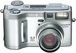
LCD MONITOR DISPLAY
b. Flash-mode indicators (p. 30)
d. Contrast-compensation display (p. 60)
e. Color-saturation-compensation
display (p. 60)
f. Exposure-compensation display (p. 46)
g. White-balance indicators (p. 54)
m. Camera-sensitivity (ISO) display (p. 57)
j. Metering-mode indicators (p. 58)
l. Camera-shake warning (p. 31)
i. Shutter-speed display
k. Aperture display
n. Manual-focus indicator (p. 56)
r. Macro indicator (p. 28)
q. Drive-mode indicators (p. 32)
o. Focus signals (p. 25)
p. Frame counter (p. 42)
v. Digital-zoom display (p. 22)
u. Image-size display (p. 40)
t. Image-quality indicator (p. 41)
s. Battery-condition indicator (p. 17)
a. Mode indicator (p. 12)
1. Focus frame (p. 48)
2. Spot metering area (p. 58)
3. AF sensors (p. 23)
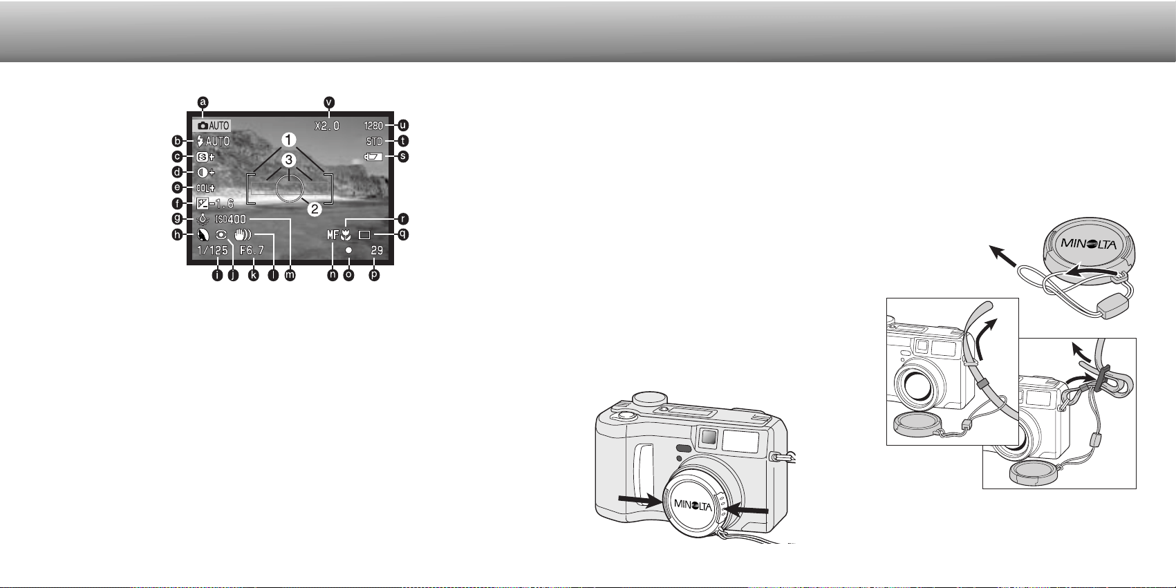
Attach the camera strap to the strap eye-
lets as shown.
• Make sure the neck strap passes through
the loop of the lens-cap strap.
• Always keep the camera strap around your
neck in the event that you drop the camera.
Attach the small strap to the lens cap by passing one of the
small loops through the eyelet on the cap (1) and then pass-
ing the other loop through the first loop (2) and tightening.
1
2
ATTACHING THE NECK STRAP AND LENS CAP
GETTING UP
AND RUNNING
4
3
Using your thumb and index
finger, pinch the outside tabs
of the lens cap to remove or
attach.
• When the camera is not in use,
always replace the lens cap.
h. Exposure-mode (p. 52)/
Digital-subject-program indicators (p. 28)
c. Sharpness display (p. 60)
Loading ...
Loading ...
Loading ...