Loading ...
Loading ...
Loading ...
* This camera is a sophisticated optical instrument. Care should be taken to keep
these surfaces clean. Please read the care and storage instructions in the back of
this manual (p. 109).
10 11
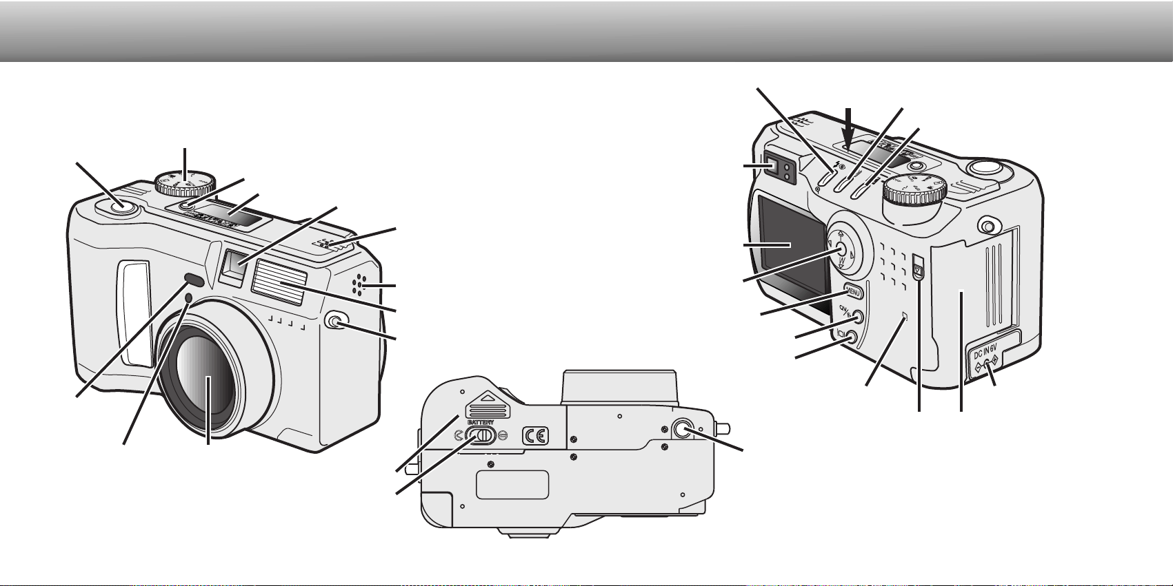
NAMES OF PARTS
CAMERA BODY
Data panel (p. 13)
Shutter-release button
Lens*
Card-slot door (p. 18)
The USB port and AV-out
terminal are located behind
the card-slot door.
Self-timer/
Remote-control
lamp (p. 32)
Flash (p. 30)
Digital-subject-program button (p. 28)
Strap eyelet (p. 15)
Viewfinder* (p. 12)
LCD monitor*
(p. 14)
Menu button
Battery-chamber lock (p. 16)
Flash mode/Magnification button (p. 30, 71)
DC terminal cover (p. 18)
Access lamp
QV/ Delete button (p. 26)
Tripod socket
Speaker
Microphone
Remote-control
receiver
Mode dial (main switch)
Viewfinder window*
Battery-chamber door (p. 16)
Card-slot door release
Drive-mode button (p. 32)
Exposure-compensation button (p. 46)
Controller
CCD plane
Display button (p. 37, 70)
Loading ...
Loading ...
Loading ...