MANUFACTURED BY:
Indoor Cycling Group GmbH
Happurger Str. 86
90482 NUERNBERG | Germany
www.indoorcycling.com
Phone: +49(0)911 / 54 44 50
CAUTION!
READ ALL PRECAUTIONS AND INSTRUCTIONS IN THIS MANUAL BEFORE YOU START
USING THIS EQUIPMENT. PLEASE KEEP THIS MANUAL FOR FUTURE REFERENCE.
IMPROPER ASSEMBLY, USE OR MAINTENANCE CAN VOID THE WARRANTY TERMS.
ADDITIONAL LANGUAGES AVAILABLE FOR DOWNLOAD AT WWW.INDOORCYCLING.COM
Version 1.0 2018 IC-LFIC8C1-01 Copyright by Indoor Cycling Group GmbH 2018 | www.indoorcycling.com
ENG
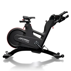
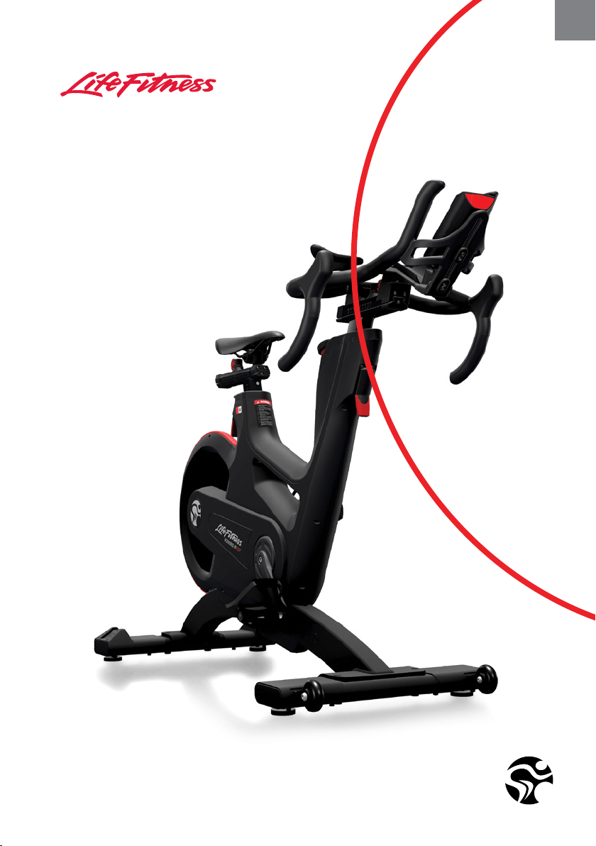
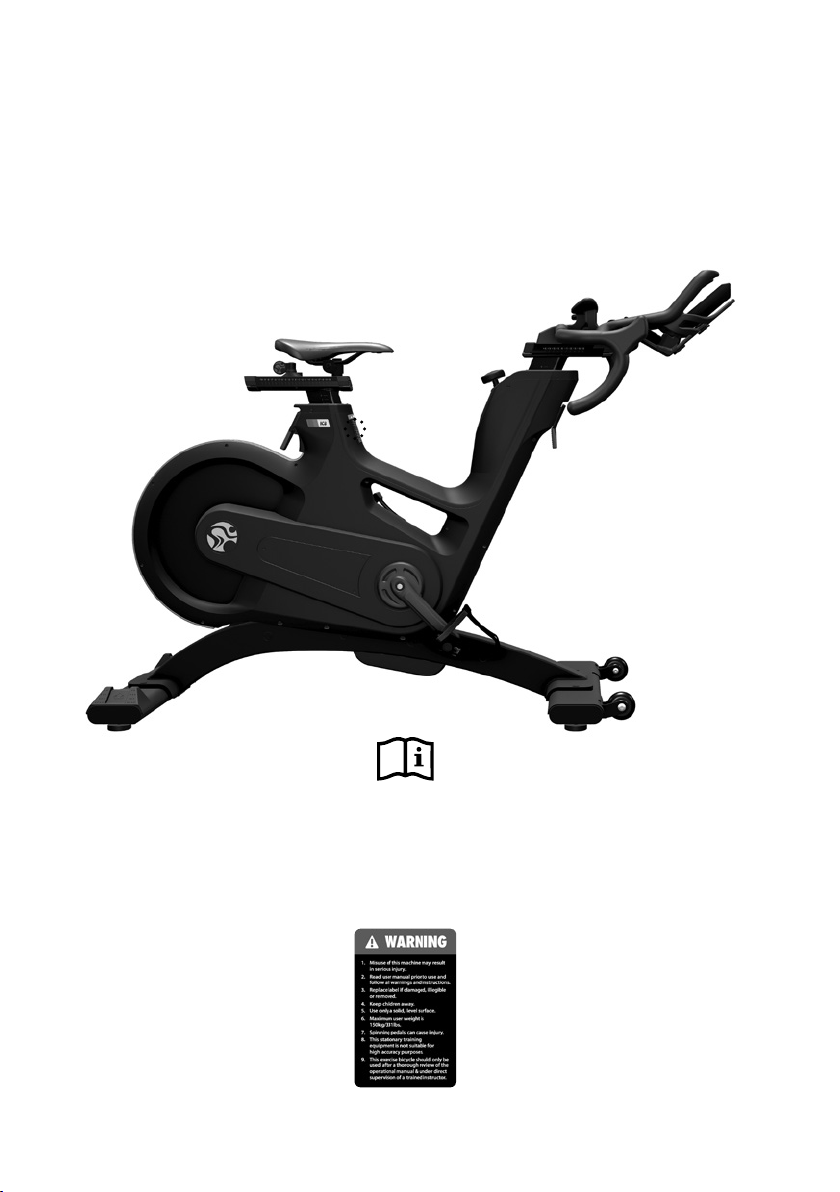
IC8 POWER TRAINER
MODEL NO:IC-LFIC8C1-01
Version 1.0 2018 IC-LFIC8C1-01 Copyright by Indoor Cycling Group GmbH 2018 | www.indoorcycling.com
ATTENTION
Warning labels on the IC8 Power Trainer must be replaced by
warning labels in your language during the assembly process.
A
A
3
ENG
ATTENTION
To download the owners manual in
your language, visit the IC8 support
section at: www.teamicg.com
Um das Handbuch in Ihrer Sprache
herunterzuladen, besuchen Sie bitte
den IC8 Support Bereich auf unserer
Webseite unter www.teamicg.com
Pour télécharger le manuel d‘utilisation
dans votre langue, consultez la section
Assistance IC8 sur: www.teamicg.com
Per scaricare il manuale nella vostra
lingua, visitate la sezione del supporto
per IC8 su: www.teamicg.com
Ga om de gebruiksaanwijzing in
uw taal te downloaden naar het IC8
supportgedeelte onder:
www.teamicg.com
Para descargarse el manual de usuario
en su idioma, por favor acceda a la
sección de soporte técnico de la bici IC8
en: www.teamicg.com
Para transferir o manual de utilizador no
seu idioma, visite a secção „Suporte“ da
IC8 em: www.teamicg.com
Besøg IC8 supportafsnittet www.
teamicg.com for at downloade
brugermanualen på dit sprog
Lataa omistajan käsikirja omalla
kielelläsi IC8-ohjeosiosta sivustolta:
www.teamicg.com
Du kan laste ned bruksanvisningen
på ditt eget språk ved å gå til IC8
støttesiden på: www.teamicg.com
Du kan hämta bruksanvisningen på ditt
språk under IC8-support på
www.teamicg.com
Aby pobrać podręcznik użytkowania w
swoim języku, należy wejść na zakładkę
IC8 support na stronie:
www.teamicg.com
Kullanıcı kılavuzunu kendi dilinizde
indirmek için www.teamicg.com
sayfasının IC8 deste bölümünü ziyaret
edebilirsiniz
在IC8的客户服务网站,您可以下载
各种语言的用户手册
www.teamicg.com
オーナーズマニュアルの各言語版
は、以下サイトの IC8 サポートペー
ジからダウンロードいただけます。
www.teamicg.com
IC8 지원 센터(www.teamicg.com)
에서 해당 언어 버전의 사용설명서를
다운로드할 수 있습니다..
EN
DE
FR
IT
NL
ES
PT
DK
FI
NO
SE
PL
TR
CN
JP
KR

Version 1.0 2018 IC-LFIC8C1-01 Copyright by Indoor Cycling Group GmbH 2018 | www.indoorcycling.com
WEIGHT OF BIKE: 56 KG
MAX USER WEIGHT: 150 KG
USER HEIGHT: SUITABLE FOR USERS BETWEEN APPROX. 155 AND 215 CM
REQUIRED FOOT PRINT: APPROX. 144 X 52 CM
MAX SADDLE & HANDLEBAR HEIGHT: APPROX. 120 CM
TECHNICAL SPECIFICATIONS:
The IC8 Power Trainer is, according to EN ISO 20957-1 and EN ISO 20957-5, a Class S B product
for use in a controlled environment such as sports or tness facilities
under the supervision of a trainer.
The IC8 Power Trainer uses a magnetic brake which provides resistance independent from the
speed (rpms) at which the training equipment is being used.
Electronic components adhere to DIN EN 60335-1 for electrical safety.
TABLE OF CONTENTS
IMPORTANT PRECAUTIONS P.5-6
GETTING STARTED P.7
HOW TO ASSEMBLE THE IC8 POWER TRAINER P.8-15
INSTALLATION AND DISPOSING OF BATTERIES P.16-17
HOW TO ADJUST THE IC8 POWER TRAINER P.18-20
HOW TO OPERATE THE IC8 POWER TRAINER P.21-24
PREVENTIVE MAINTENANCE P.25-29
MAINTENANCE ACTIVITY AND REQUIRED SCHEDULE P.30-31
SPARE PARTS P.32-33
WARRANTY P.34

5
ENG
IMPORTANT PRECAUTIONS
WARNING!
To reduce the risk of serious injury due to improper use of the
training equipment, carefully read and adhere to the following
important precautions and information before operating the bike.
1. It is the responsibility of the owner to ensure that all users
are informed of all warnings and precautions for proper use
of the training equipment and it is only authorized for use
in a supervised environment with qualied instructors.
2. Do not operate the training equipment until it has been
properly assembled and inspected as described in this manual.
3. Keep the training equipment away from moisture and
dust. Do not place the training equipment in a garage,
covered patio, near water or pools. Operating temperature
of the training equipment has to be between
15°C~ 40°C Celsius (59°~104°F) at max. humidity of 65%.
4. Always place the training equipment on a stable, level surface.
If the training equipment is to be placed on a hardwood oor
or carpet, it is recommended to place a oor mat beneath
the bike, to protect the oor from becoming damaged.
5. The level of safety of the training equipment can only be
guaranteed if it is regularly checked for possible damage as
well as wear and tear (e.g. xing points, pedals, toe straps, etc.).
Consult an authorized service provider or the manufacturer
to ensure the regular inspections are properly carried out.
6. Carry out all maintenance, care and service procedures as
described in this manual on a regular basis. Defective parts
must be replaced immediately, and the device must not be
used until the repairs have been carried out. Only use original
parts from the manufacturer. Repairs must only be carried
out by from manufacturer authorized service technicians.
7. Unsupervised children should be kept away
from the training device at all times.

Version 1.0 2018 IC-LFIC8C1-01 Copyright by Indoor Cycling Group GmbH 2018 | www.indoorcycling.com
WARNING!
If you have pre-existing health problems or a disability, it is
recommended that you consult your physician, in order to
nd the training method which is best suited to you. Incorrect
or extensive training can result in serious health injuries.
The manufacturer expressly assumes no responsibility for
health risks, personal injury, property damage or consequential
damages sustained by or through the use of this device, unless
it is a case of consequential damage which can be traced
back to faulty material and/or manufacturing, and which
come under the responsibility of the manufacturer.
8. WARNING: The training equipment can be used by children
aged from 14 years and above and persons with lack of
experience and knowledge if they have been given supervision
or instruction concerning use of the appliance in a safe way
and understand the hazards involved. Persons with reduced
physical, sensory or mental capabilities are prohibited from
using the training equipment. Children shall not play with
the training equipment. Cleaning and user maintenance
shall not be made by children without supervision.
9. The training equipment must not be used by
persons exceeding weight of 330 lbs/150 kg.
10. Always wear appropriate tight-tting cycling or
athletic attire and sturdy shoes, preferably cycling shoes,
while operating the bike. Unfastened shoelaces may
become caught in the drive system and lead to injury.
11. If you feel pain or dizziness while exercising, stop
immediately. It is recommended that you consult a doctor if
the pain does not subside for an extended period of time.
12. All data shown on the display serve merely
as information and to help guide training. Only
exercise within your physical limitations.
13. This stationary training equipment is not
suitable for high accuracy purposes.
IMPORTANT PRECAUTIONS
7
ENG
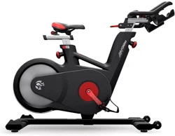
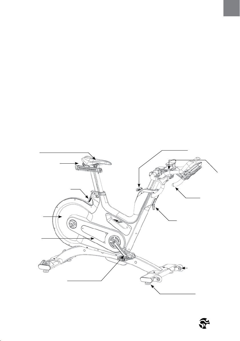
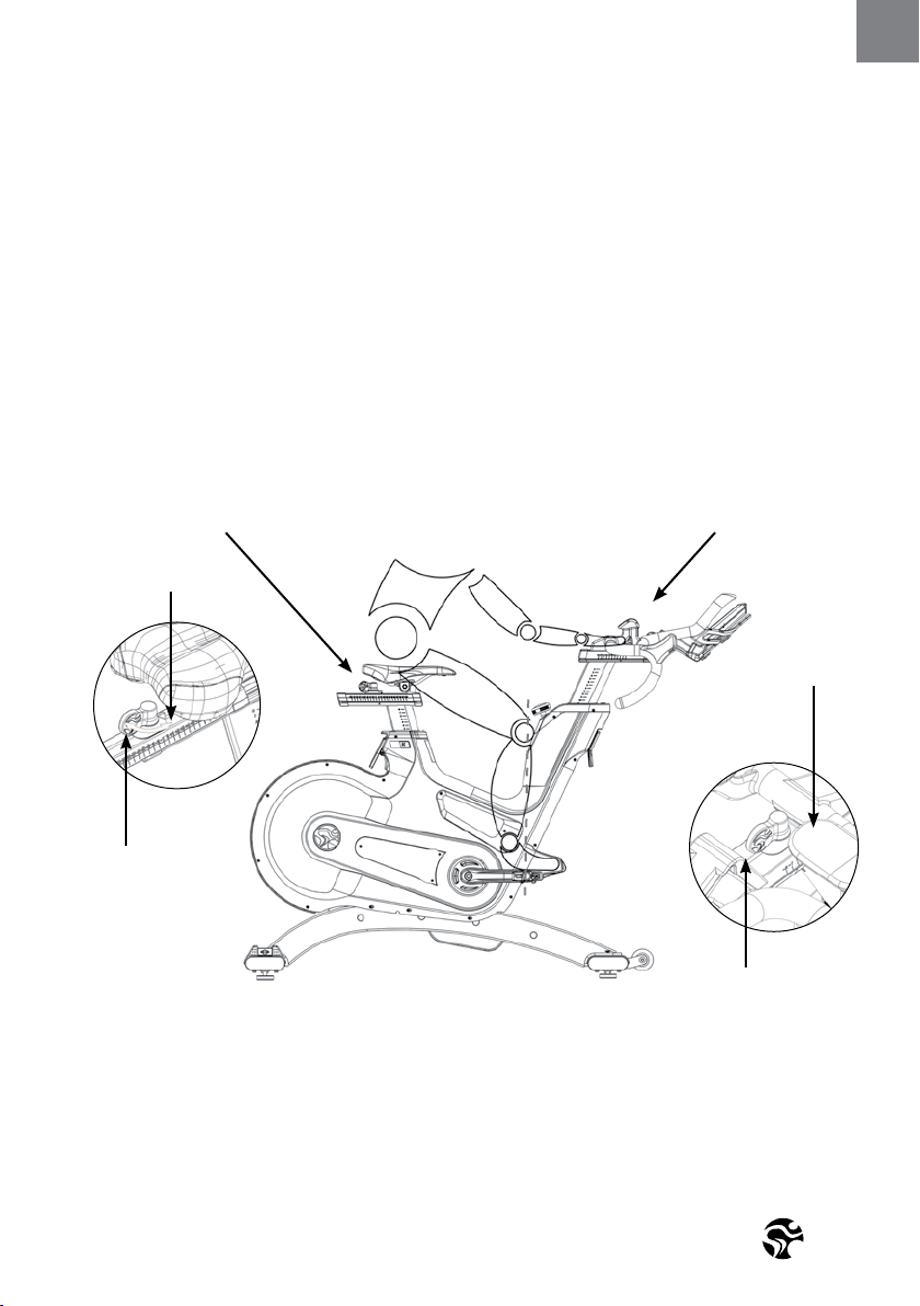
FLIP LEVER FOR VERTICAL
SADDLE ADJUSTMENT
DEAR CUSTOMER,
We would like to thank you for your condence and purchase. With the IC8 Power Trainer,
you have chosen a high-quality product, which is designed according to the latest technical
developments and thus fulls the highest standards in quality and reliability.
This high level of reliability can however only be ensured with regular care and maintenance.
Adhering to the maintenance procedures outlined in this manual will ensure a maximized
stability and prolonged lifespan in return for minimal maintenance eort. This will guarantee
long-standing, interruption-free operation.
Instructions on operation and managing training for the computer can be found in it‘s manual
also included with delivery.
GETTING STARTED
SADDLE
THUMB LEVER FOR
HORIZONTAL SADDLE
ADJUSTMENT
FLYWHEEL
SHROUD
DUAL SIDED SPD PEDAL
THUMB LEVER
FOR HORIZONTAL
HANDLEBAR
ADJUSTMENT
FLIP LEVER FOR VERTICAL
HANDLEBAR ADJUSTMENT
HANDLEBAR
RESISTANCE KNOB
TRANSPORT WHEELS
LEVELING FEET
WARNING!
You will nd the production code for the IC8 trainer on the tag plate which is located on the lower left side of the frame
tube. Please enter this production code into care and maintenance lists.
It is a strict requirement to provide the production code in all warranty claims.
Version 1.0 2018 IC-LFIC8C1-01 Copyright by Indoor Cycling Group GmbH 2018 | www.indoorcycling.com
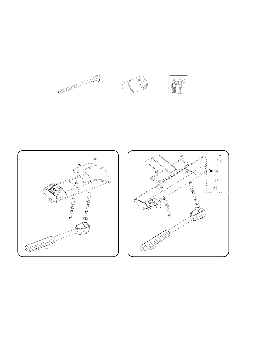
HOW TO ASSEMBLE THE
IC8 POWER TRAINER
TORQUE WRENCH 17 MM 2
PEOPLE
WARNING!
Avoid high uctuations in temperature when transporting the bike from the store to the
installation site. If great uctuations in temperature cannot be avoided, please allow the bike
to acclimatize to the surrounding temperature before proceeding with assembly.
WARNING!
Please ensure that bolts are tightened with signicant force to minimize loosening during use.
If bolts are loosened after initial assembly, we recommend using medium-strength LOCTITE®
243 when reassembling.
1. 2.
50 NM
50 NM
9
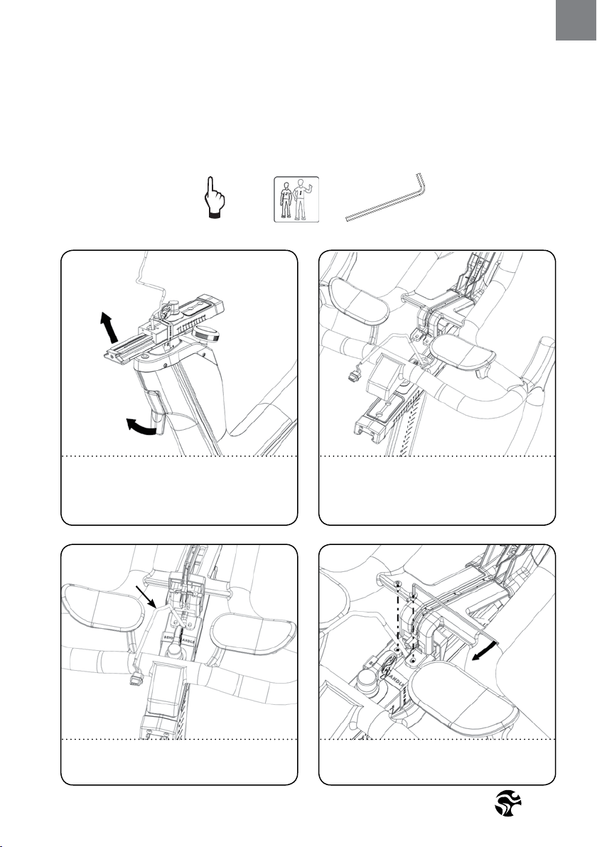
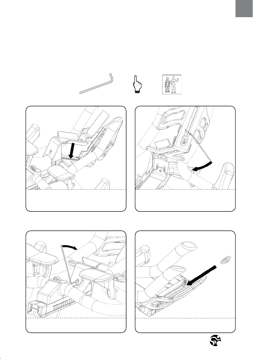
ENG
HOW TO ASSEMBLE THE
IC8 POWER TRAINER
2
PEOPLE
3. 4.
SET THE VERTICAL ADJUSTMENT OF THE
HANDLEBAR STEM TO THE HIGHEST POSITION
BEFORE BEGINNING WITH ASSEMBLY. DO NOT
REMOVE WARNING TAPE FROM THE SLIDER
PRIOR TO THE HANDLEBAR BEING ASSEMBLED.
WHEN SETTING THE HANDLEBAR INTO POSITION ON
THE SLIDER, MAKE SURE THAT THE CABLE IS FACING
UPWARDS THROUGH THE HANDLEBARS.
4.1
5.
MAKE SURE THAT THE CABLE IS IN THE ABOVE
POSITION BEFORE MOVING TO THE NEXT STEP.
LOOSELY FIT SCREWS BUT DO NOT TIGHTEN THEM.
HAND TIGHT
2.5 MM
Version 1.0 2018 IC-LFIC8C1-01 Copyright by Indoor Cycling Group GmbH 2018 | www.indoorcycling.com
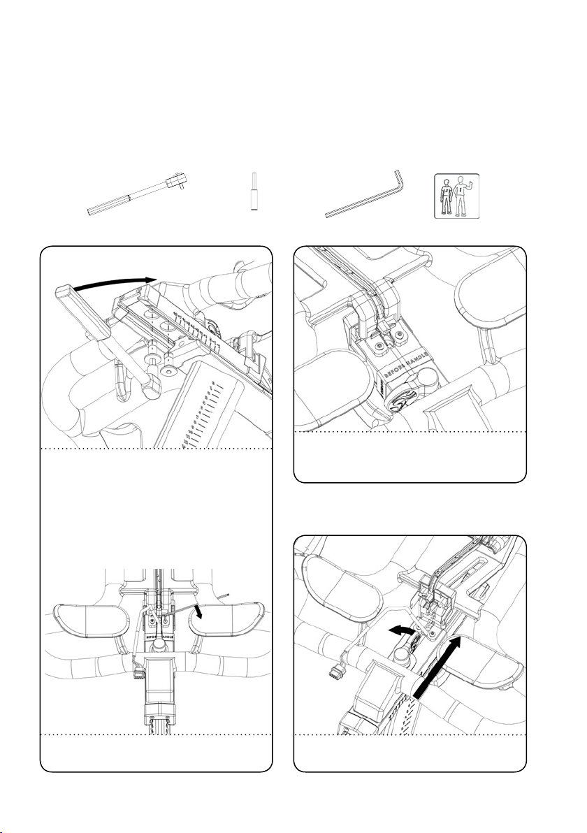
HOW TO ASSEMBLE THE
IC8 POWER TRAINER
6. 7.
TORQUE THE BOLTS WITH 30 NM USING A TORQUE
WRENCH.
THE SUPPLIED COUNTERSUNK BOLTS ARE COATED
WITH NYLOC AT THE FACTORY TO PREVENT THEM
FROM BECOMING LOOSE DURING USE.
IF BOLTS ARE LOOSENED AFTER INITIAL ASSEMBLY,
WE RECOMMEND USING HIGH-STRENGTH LOCTITE®
2701 WHEN REASSEMBLING.
AFTER ASSEMBLY, REMOVE THE WARNING TAPE.
PUSH THE HANDLEBARS ONLY FORWARD!
NEVER MOVE THE HANDLEBAR BACKWARDS.
TORQUE WRENCH 6MM HEX SOCKET 2
PEOPLE
30 NM
8.
OPEN THE THUMBLEVER AND PUSH
THE HANDLEBAR FORWARD.
HAND TIGHTEN THE BOLTS FROM STEP 5.
2.5 MM
11
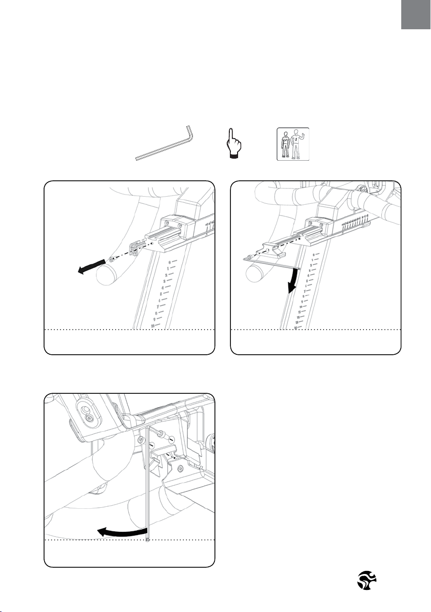
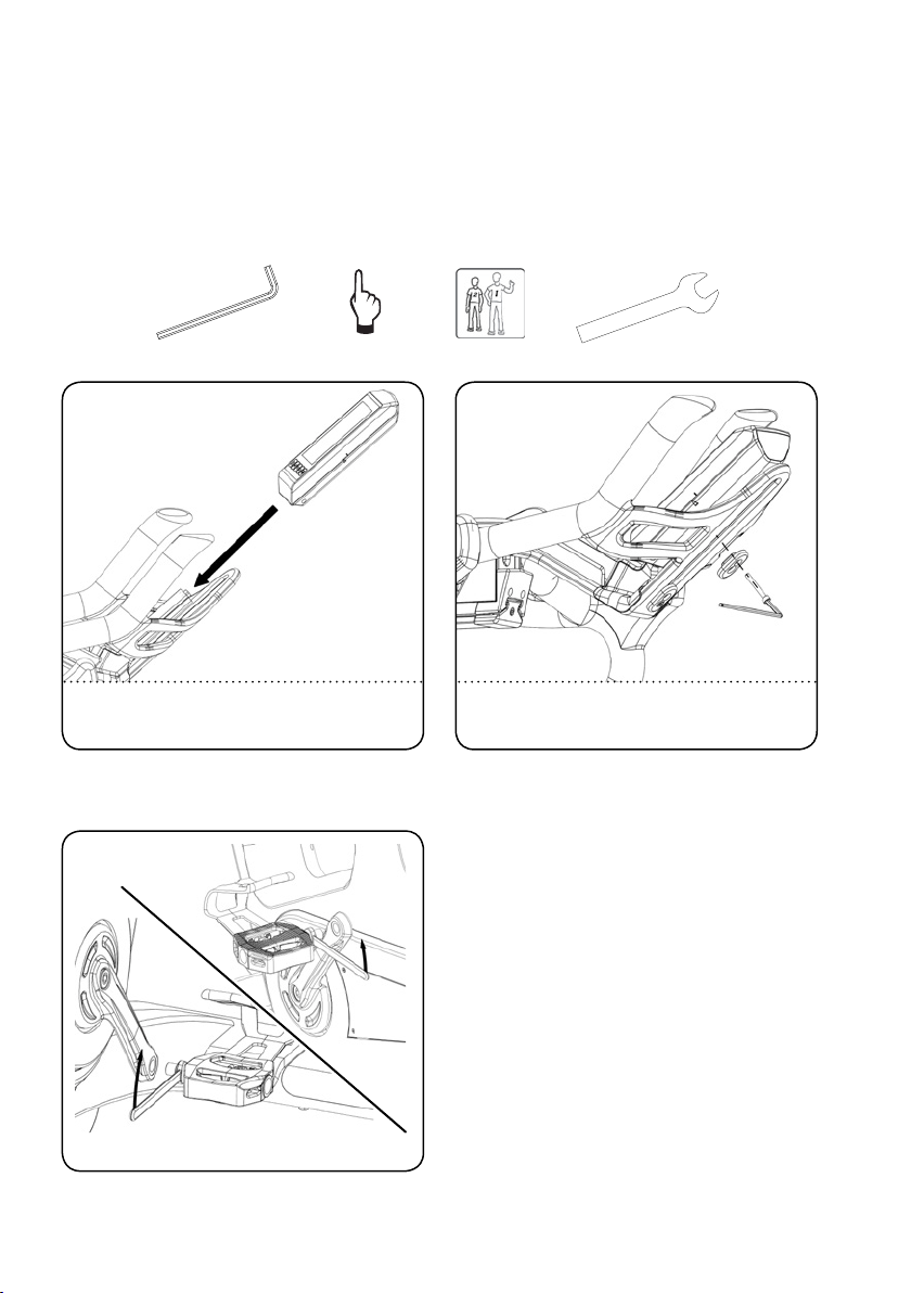
ENG
HOW TO ASSEMBLE THE
IC8 POWER TRAINER
2
PEOPLE
9.
6.
REMOVE THE LIMIT STOP FROM INSIDE THE
SLIDER. THE BOLT IS REUSED IN STEP 10.
3MM HAND TIGHT
MOUNT THE ENDCAP AND HANDTIGHTEN
USING THE LIMIT STOP BOLT.
10.
6.
11.
MOUNT THE ENDCAP FOR THE UPPER
HANDLEBAR SLIDER AND HANDTIGHTEN
USING THE LIMIT STOP BOLT.
Version 1.0 2018 IC-LFIC8C1-01 Copyright by Indoor Cycling Group GmbH 2018 | www.indoorcycling.com
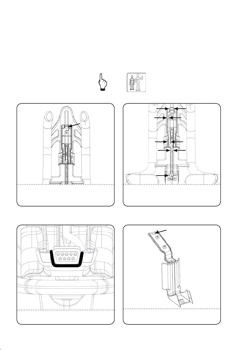
HOW TO ASSEMBLE THE
IC8 POWER TRAINER
2
PEOPLE
PLACE THE SMALL SIDE OF THE CONNECTOR
INTO THE BOTTOM OF THE BRACKET
HAND TIGHT
REMOVE THE BACKING OF THE TAPE FROM
THE COMPUTER BRACKET COVER.
14.13.1
REMOVE THE BACKING OF THE DOUBLE SIDE TAPE. INSERT THE CABLE INTO THE SLOTS AS DEPICTED ABOVE.
POSITION THE CONNECTOR ON THE TAPE AT THE TOP
OF THE BRACKET AND PRESS THE CONNECTOR AT
THE END OF THE CABLE INTO POSITION (SEE12.1).
12.
13.
13
ENG
16.
HAND TIGHTEN THE COVER TO THE COMPUTER
BRACKET WITH THE COUNTERSUNK BOLT.
POSITION THE COVER ON THE COMPUTER BRACKET.
15.
HOW TO ASSEMBLE THE
IC8 POWER TRAINER
17.
TURN THE THUMBLEVER TO THE SIDE
AND HAND TIGHTEN THE BOLT.
SLIDE A SPACER WITH THE SMALL SIDE DOWN,
BETWEEN THE HANDLEBAR AND COMPUTER BRACKET.
16.1
2,5 MM HAND TIGHT 2
PEOPLE
Version 1.0 2018 IC-LFIC8C1-01 Copyright by Indoor Cycling Group GmbH 2018 | www.indoorcycling.com
20.
R
L
55 NM
WARNING!
Attach the pedal marked R on the right
crank and tighten by turning clockwise
(standard right-hand thread). Attach the
pedal marked L on the left crank and tighten
by turning counter-clockwise (left-hand
thread). Please make sure that both pedals
are fastened with sucient force (55 NM),
to ensure that the bolt does not become loose
during use.
The threads are provided with TufLok® at the
factory to prevent them from becoming loose
during use. If bolts are loosened after initial
assembly, we recommend using medium-
strength LOCTITE® 243 when reassembling.
OBSERVE ASSEMBLY
INSTRUCTIONS!
15 MM
PEDAL WRENCH
HOW TO ASSEMBLE THE
IC8 POWER TRAINER
2
PEOPLE
3MM HAND TIGHT
SLIDE THE COMPUTER ON THE BRACKET. HAND TIGHTEN THE COMPUTER TO THE
HANDLEBAR USING THE SECOND SPACER.
18. 19.
15
ENG
21.
CHECK THE VERTICAL ADJUSTMENT, WITH THE FLIP LEVER OPENED,
FOR EASE OF MOTION WHEN ADJUSTING.
CHECK THE CLAMPING FORCE OF THE VERTICAL ADJUSTMENT WITH THE
FLIP LEVER CLOSED. MAKE SURE THE VERTICAL ADJUSTMENT PERFORMS SUFFICIENTLY.
ADJUST IF REQUIRED REFERING TO SERVICE GUIDELINES ON AVAILABLE ON
MANUFACTURER‘S SERVICE WEBSITE OR CONTACT YOUR LOCAL DISTRIBUTOR.
22.
HOW TO ASSEMBLE THE
IC8 POWER TRAINER
2
PEOPLE
3MM HAND TIGHT

Version 1.0 2018 IC-LFIC8C1-01 Copyright by Indoor Cycling Group GmbH 2018 | www.indoorcycling.com
INSTALLATION
Instructions stated in this manual must be performed during initial installation of the
training equipment in order to ensure optimal performance and a long lifespan. Please
read and follow the following instructions carefully. If the bike is not installed and
congured as described, the components may be subjected to excessive wear and tear
and the bike may become damaged. If you have any questions regarding installation,
please contact service@indoorcycling.com.
Please note: Lubricants are required for some maintenance procedures. Please only use an
acid- and solvent-free spray lubricant and white lithium grease.
1. Make sure the bike is level. If bike rocks on the oor, turn the levelling feet underneath the
front and/or rear stabilizer until the rocking motion is eliminated. Make sure that the levelling
feet are not screwed out further than 10 mm.
2. Check that both crank arm Allen bolts, with which the cranks (on the right and left side of the
bottom bracket) are fastened, are secure (tightening torque 60 NM). These bolts are provided
with TufLok® at the factory to prevent them from becoming loose during use.
If the bolts become lose, we recommend applying medium-strength LOCTITE® 243 and then
reattaching the crank xing bolts with a tightening torque of 60 NM.
3. Wipe down bike frame with a rag moistened with solvent-free spray lubricant.
4. Some parts of the bike may become loose during shipment. Check crank arms and all exposed
screws, bolts and nuts, and make sure that they are all secure and properly tightened.
CUSTOMER SERVICE
1. Provide the customer with basic maintenance instructions, and direct them to detailed
maintenance instructions.
2. Have the sign-o sheet for the manual, explanation of maintenance procedures and
verication of impeccable condition of the bikes conrmed by the customer when handing over
the goods. A copy of this conrmation counter-signed by yourself is withheld by the customer.
3. Repairs must only be carried out by manufacturer authorised service technicians.

17
ENG
DISPOSING OF BATTERIES
BATTERIES MAY NOT:
• come into contact with re.
• come into contact with coins or other metallic objects.
Products or batteries labelled with this symbol may not be disposed of along with normal
household refuse. For proper disposal, please nd out about the applicable laws or guidelines
on disposing of electrical devices and batteries in your local area and adhere to them.
Version 1.0 2018 IC-LFIC8C1-01 Copyright by Indoor Cycling Group GmbH 2018 | www.indoorcycling.com
The training equipment can be very easily adjusted, depending on the requirements of various
user groups. This enables maximum riding comfort to be ensured whilst achieving optimal
training results. The congurations described in the following paragraphs demonstrate
just a few of the most often used adjustment variations of which the training equipment is
capable. It is up to the user to adjust the training equipment to a riding position best suited
to their requirements.
ADJUSTING THE SEAT HEIGHT:
Sit on the saddle and ensure that your hip is not tilted to one side when the pedal has assumed
the position as shown in the picture. Place your shoes in the toe clips (cages) on the pedals, or
in the SPD cleats if you are using cycling shoes, if your bike is tted with a combi pedal system.
HOW TO ADJUST THE
IC8 POWER TRAINER
VERTICAL HANDLEBAR
ADJUSTMENT
WARNING!
Do not adjust seat and handlebar during exercise. Ensure that all levers (vertical and horizontal)
are closed, before you sit on the bike and always step o the bike when making adjustments to
the handlebars and/or saddle.
Start pedalling slowly, until the pedal has reached the position as shown in the picture.
The vertical saddle sliders should be adjusted so that your knees are always slightly bent
when this pedal position is reached, without dropping your hip one side. Rule of thumb:
When standing next to the bike, the upper edge of the saddle should be a hand‘s width/four
ngers below your iliac crest. Please avoid cycling with your knees fully extended or your hip
tilted to one side.
VERTICAL SADDLE
ADJUSTMENT
CLOSED
CLOSED
OPEN
OPEN
19
ENG
WARNING!
Ensure that all levers (vertical and horizontal) are closed, before sitting on the bike and always step o the bike when
making adjustments to the handlebars and/or saddle.
ADJUSTING THE SADDLE HORIZONTALLY:
Properly positioning the saddle horizontally is very important in order to avoid injury to the
knees. Sit on the saddle and move the pedals until the crank arms are in the horizontal position.
The knee of your forward-facing leg should be positioned directly above the centre of the pedal.
If this does not correspond to your bike‘s setting, please align the horizontal saddle adjustment
to the front or rear in order to attain this seat position.
HOW TO ADJUST THE
IC8 POWER TRAINER
HORIZONTAL
SADDLE ADJUSTMENT
HORIZONTAL
HANDLEBAR ADJUSTMENT
OPEN
OPEN
CLOSED
CLOSED
Version 1.0 2018 IC-LFIC8C1-01 Copyright by Indoor Cycling Group GmbH 2018 | www.indoorcycling.com
HOW TO ADJUST THE
IC8 POWER TRAINER
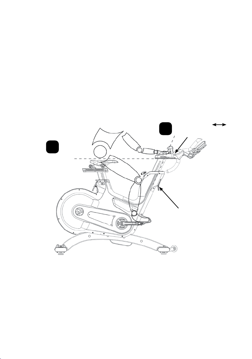
The next step is to adjust the horizontal position of the handlebar as precisely as possible to your
height. An ideal and protective seating position for inexperienced riders is achieved if your back
assumes an inclination at an angle of 45°.
The handlebars oer a wide variety of hand positions and adjustment possibilities, which provide
the experienced rider with every possibility to nd his/her ideal seating and hand positioning.
It is recommended to change hand positions frequently during extended workouts in order to
minimise one-sided and monotonous exertions on your muscles, ligaments and joints.
HANDLEBAR POSITIONING:
Begin with the top of the handlebars at approximately the same height as the saddle
(dotted horizontal line A in the drawing below) for inexperienced users set to the “0“ marking
(see dotted vertical line B in the drawing below). If your knees touch the handlebars or if
you experience back discomfort when pedalling in the standing riding position for extended
periods, the handlebars should rst be adjusted slightly higher.
A.
B.
Horizontally
adjusting the handlebars
using the lever
Vertically
adjusting the handlebars
using the lever

21
ENG
HOW TO OPERATE THE
IC8 POWER TRAINER
RESISTANCE ADJUSTMENT:
The resistance adjustment can be set precisely and regulated in ne increments according to
the requirements of the cyclist using the resistance adjustment knob with a range of motion
of 300°. The resistance in % (where 0% is no resistance and 100% is maximum resistance) is
also displayed on the bike computer.
To increase the resistance, turn the resistance adjustment knob clockwise and to decrease
the resistance, turn it counter-clockwise. The resistance will also increase as the pedalling
frequency increases due to the magnetic brake system tted on this bike.
Never pedal backwards, as this can loosen the bolts between the pedals and the crank arm
and the two may even become detached. During training, please make sure your shoes are
placed in the toe clips (cages) provided or if you are using cycling shoes, with SPD cleats.
WARNING!
The bike shall only be operated in forward pedaling motion. Do not attempt to adjust seat and
handlebar in vertical or horizontal position while riding or seated.
Version 1.0 2018 IC-LFIC8C1-01 Copyright by Indoor Cycling Group GmbH 2018 | www.indoorcycling.com
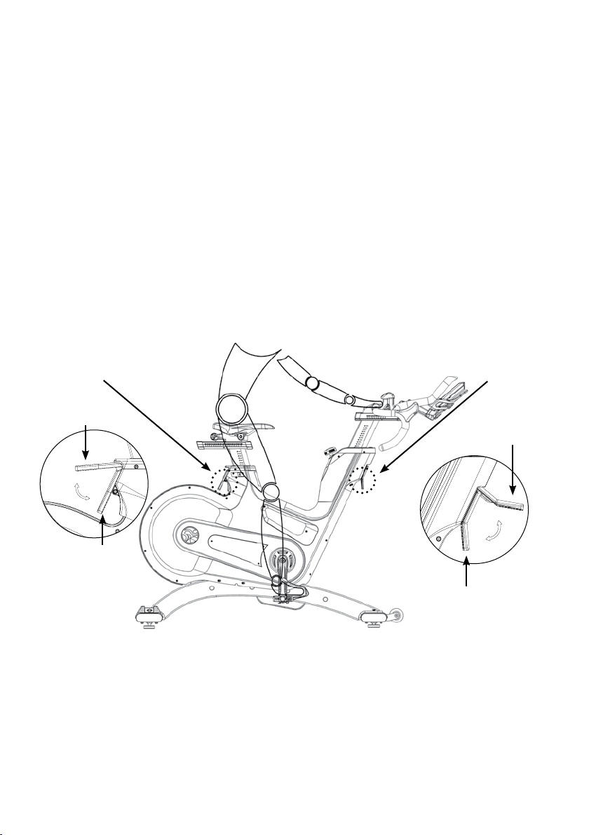
HOW TO OPERATE THE
IC8 POWER TRAINER
MOVING THE BIKE:
It is recommended that two people move the bike. In order to prevent accidents and damage to the plug-in sockets of
the handlebars it is necessary to rmly x the vertical handlebar adjustment before the wheel is tilted. Please take extra
care when moving the bike over uneven surfaces. A second person is advisable here, to prevent the bike from tilting to
one side. Allow a minimum safety distance away from the nearest equipment, objects or walls as illustrated below.
RESISTANCE KNOB (TURN RESISTANCE ADJUSTMENT KNOB)
Turn the knob in clockwise direction to increase the resistance and counter clockwise direction to decrease resistance.
For safety reasons, please always make sure you pedal in a controlled manner and adjust your pedalling frequency to
your own cycling capabilities.
3.9“
(10cm)
23.6“
(60cm)
23.6“
(60cm)
3.9“
(10cm)
23.6“
(60cm)
23.6“
(60cm)
23
ENG
HOW TO OPERATE THE
IC8 POWER TRAINER
Check the stability of the bike where it is to be operated and if necessary adjust the
levelling feet underneath the front or rear stabilizers to ensure the desired stability.
IMPORTANT!
Please do not unscrew the levelling feet more than 1 cm! The free standing bike
shall only be installed and operated on a horizontal, stable and leveled oor.
LEVELLING FEET
Version 1.0 2018 IC-LFIC8C1-01 Copyright by Indoor Cycling Group GmbH 2018 | www.indoorcycling.com
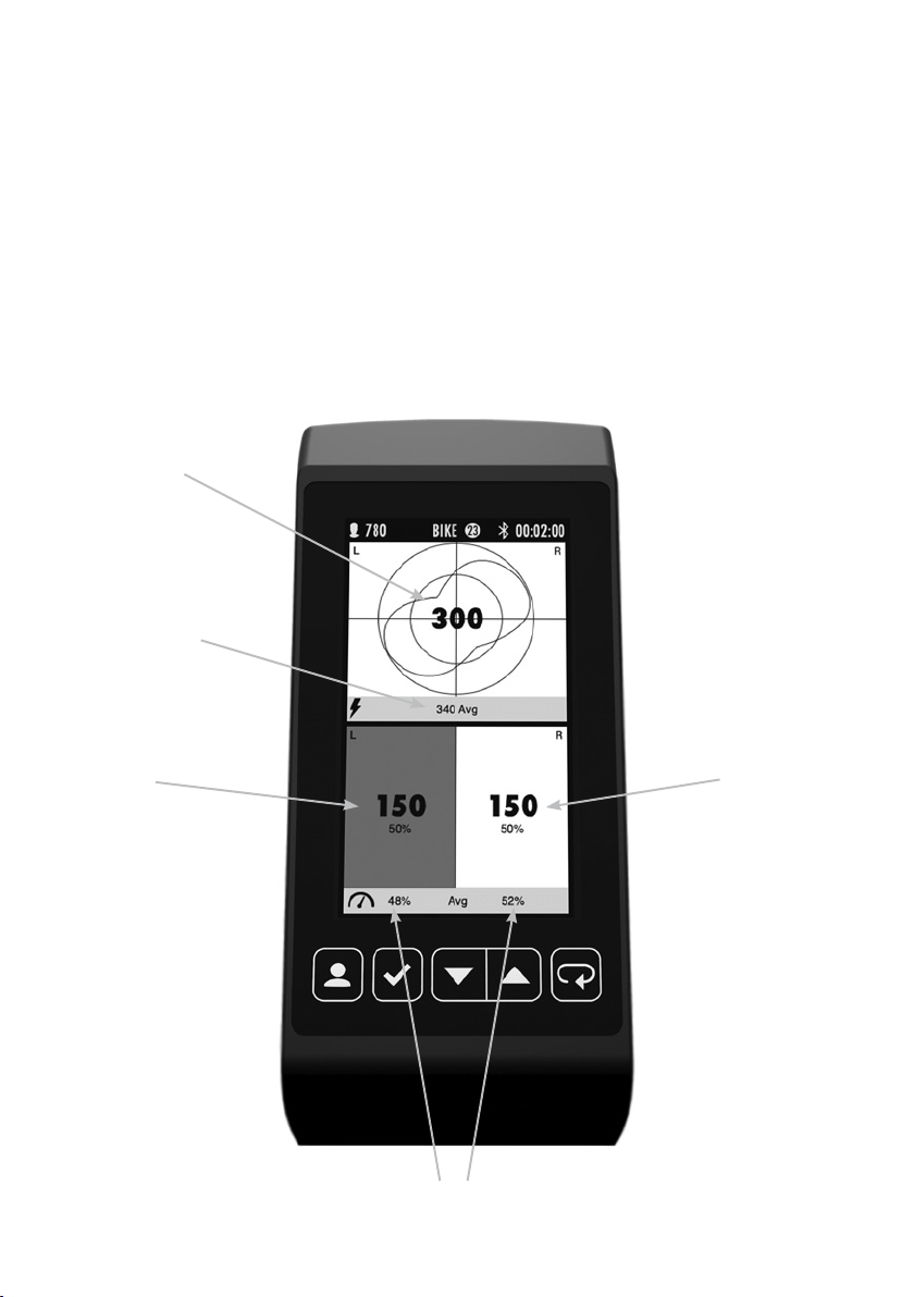
HOW TO OPERATE THE
IC8 POWER TRAINER
The IC8 power trainer has the abilityto display in real time how you apply force
through eachpedal stroke and the balance between your left and right leg and
to provide a summary of your overall performance at the end of your workout.
The screen can be entered by toggling through the workout screen with the
up/down arrow keys.
AVERAGE LEFT AND RIGHT POWER BALANCE
TOTAL POWER
AND RIGHT/LEFT
BALANCE
LEFT AND RIGHT
COMBINED CURRENT
AVERAGE POWER
LEFT POWER
RIGHT POWER

25
ENG
WARNING!
Please carefully observe the following instructions. The maintenance and care procedures
must be performed in the regularity set out, to ensure maximum operating safety and lifespan.
Irregularly observed maintenance and care procedures will lead to increased wear to the
product and will void the warranty. If you have any further questions on this topic, please
contact our technical support.
Please only use an acid- and solvent-free maintenance and care agent to prevent damage to
components of the bike.
DAILY MAINTENANCE:
1. Make sure that the bike is horizontal, leveled and does not rock
(if necessary adjust as described on p.23).
2. Cleaning: The bike must be regularly cleaned after each use for reasons of hygiene. Ensure
that there are sucient soft cloths or paper towels, maintenance and disinfection agent
available. First disinfect the saddle and handlebars with a suitable agent and then wipe all bodily
residues o the entire bike.
WEEKLY MAINTENANCE:
1. Cleaning: Depending on how often the bike is used, it must be extensively cleaned once
a week. To do this, spray a maintenance spray onto a soft cloth and clean all plastic parts,
the entire ywheel, exposed frame components including stabilizers and the plastic casing.
Never spray maintenance spray or anything else directly onto the ywheel or pedal to ease
cleaning, as this could cause the drive belt to slip during use, or damage internal components.
PREVENTIVE
MAINTENANCE
Version 1.0 2018 IC-LFIC8C1-01 Copyright by Indoor Cycling Group GmbH 2018 | www.indoorcycling.com
GREASE
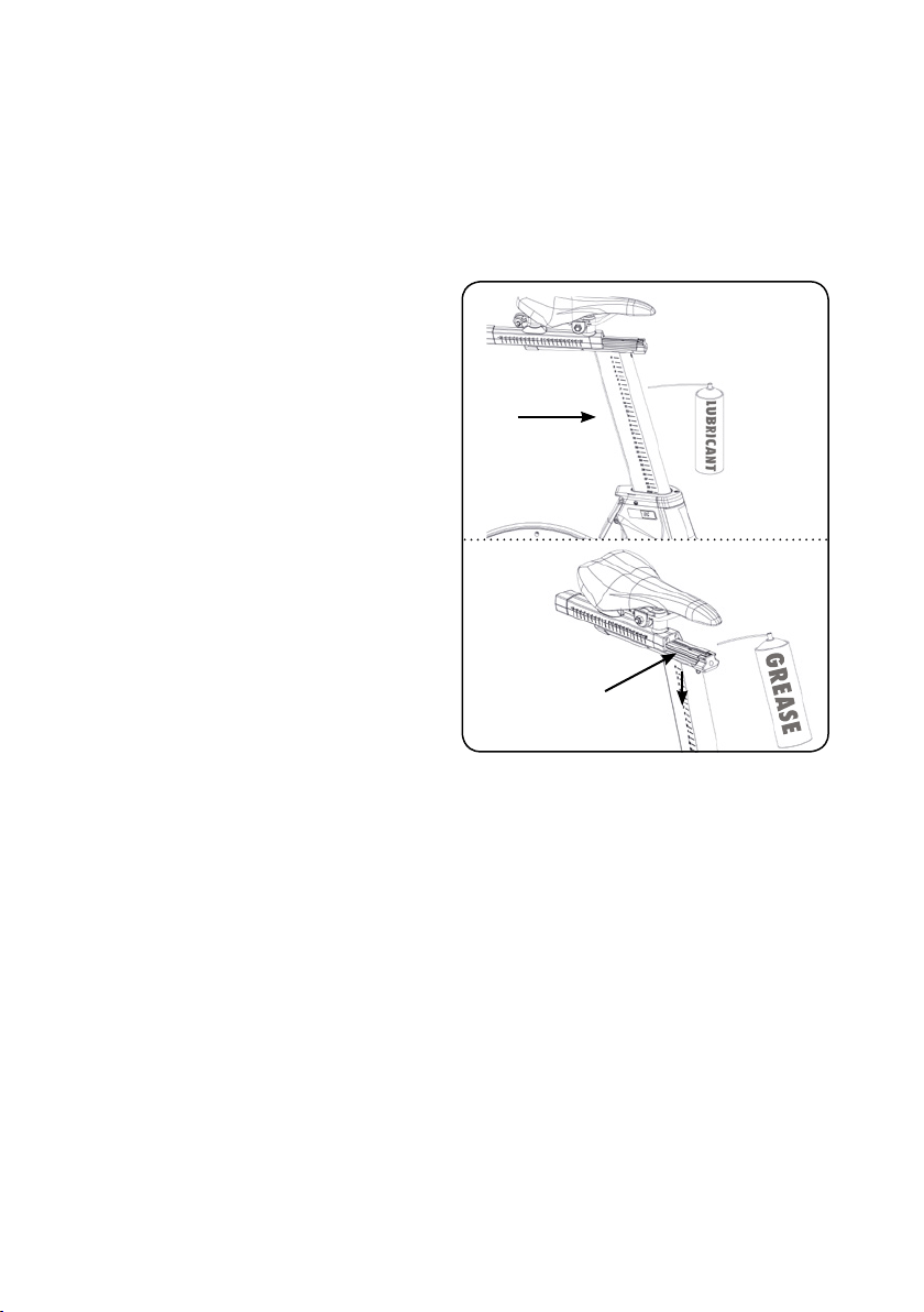
BI-WEEKLY MAINTENANCE:
1. Saddle adjustments: To maintain the
easy adjustment, the vertical and horizontal
saddle posts must be regularly cleaned and
lubricated. To do this, position the vertical
saddle post (A) in the uppermost position,
spray with maintenance spray and rub down
the entire exterior surfaces including the
horizontal post with a soft cloth.
Clean sweat residues o the contact surfaces
(B) of the horizontal saddle post beforehand
and if necessary apply a small amount of clear
lithium or silicone grease.
PREVENTIVE
MAINTENANCE
A
B
1.
B
27
ENG
GREASE
A
B
B
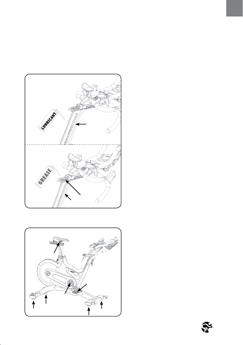
2. Handlebar: To maintain the easy
adjustment of the handlebar posts, the
vertical and horizontal handlebar posts
must be regularly cleaned and lubricated.
To do this, position the handlebar (A) in the
uppermost position, spray the handlebar
posts with maintenance spray and rub
down the entire exterior surfaces including
the horizontal post with a soft cloth.
Clean sweat residues o the contact
surfaces of the horizontal handlebar post (B)
beforehand and if necessary apply a small
amount of clear lithium/silicone grease.
MONTHLY MAINTENANCE:
1. Connecting elements: During the course
of regular maintenance and care procedures,
all bolts, nuts etc. on the bike must be
checked for rm seating and function, and
parts showing wear or damage (saddle,
pedal teeth, pedals, SPD system) replaced.
PREVENTIVE
MAINTENANCE
1.
2.
25 NM
55 NM
60 NM
Version 1.0 2018 IC-LFIC8C1-01 Copyright by Indoor Cycling Group GmbH 2018 | www.indoorcycling.com
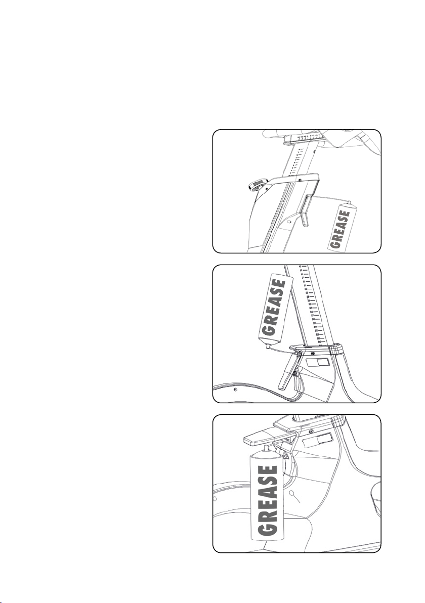
USER-DEFINED MAINTENANCE:
1. Vertically adjusting the
handlebar and saddle:
To ensure the easy adjustment of the
vertical handlebar and saddle posts, it is
recommended that you check the clamping
mechanism and if necessary apply a small
amount of clear lithium/silicone grease to
the vertical clamping mechanism of the
handlebar posts (1) and saddle post (2/3).
PREVENTIVE
MAINTENANCE
GREASE
GREASE
1.
2.
3.
29
ENG
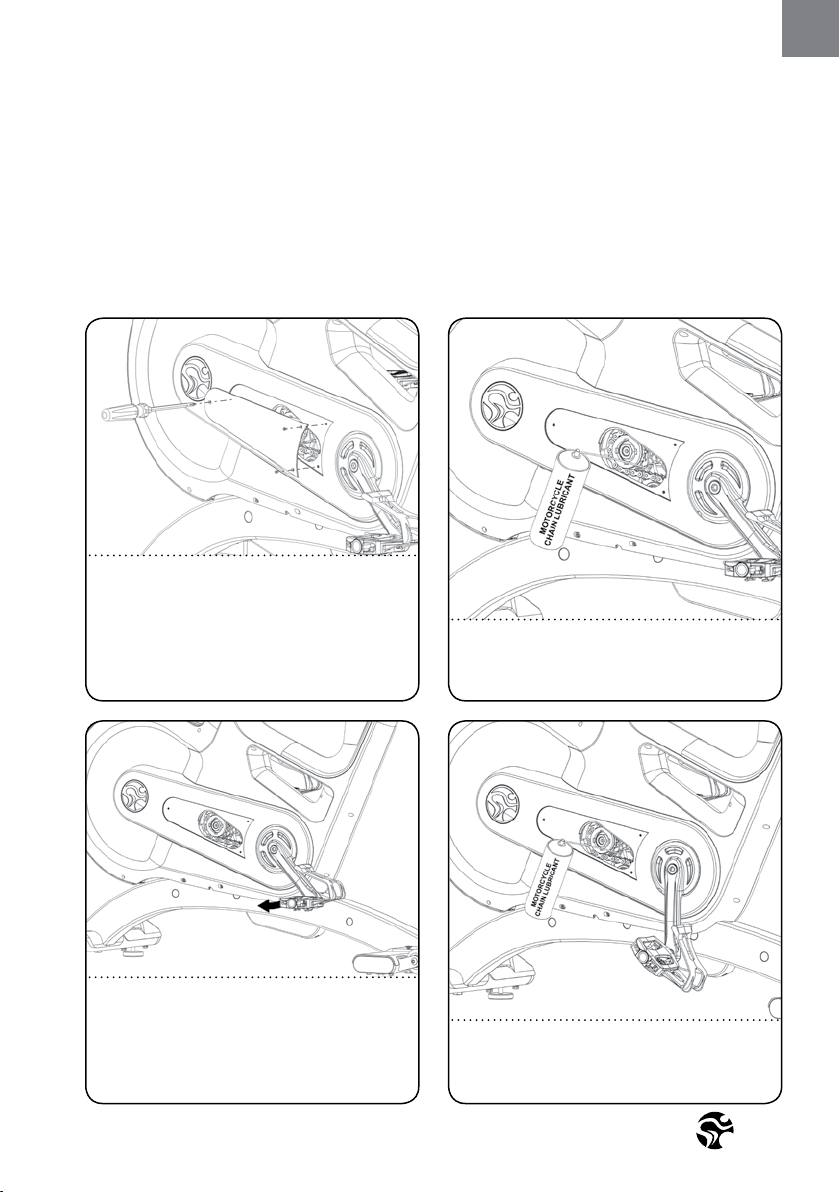
PREVENTIVE
MAINTENANCE
CHAIN LUBRICATION:
Lubricate the chain once every 150 hours of use with a motorcycle chain lubricant.
Spray Motorcycle Chain Lubricant on the
exposed section of the chain only when
the crank / chain is not moving.
Slowly turn the crank until unlubricated
chain is exposed and stop the crank.
WARNING
Never turn the crank and lubricate the
chain while it is turning.
1.
2.
3. 4.
Repeat the process from step 2 until the
complete chain is lubricated.
Remove the chain cover by removing the
3 screws using a Phillps head screwdriver.
WARNING
Once the cover is removed, you are
exposing moving parts. Never use the bike
when the cover is not mounted.

Version 1.0 2018 IC-LFIC8C1-01 Copyright by Indoor Cycling Group GmbH 2018 | www.indoorcycling.com
MAINTENANCE ACTIVITY
AND REQUIRED SCHEDULE
EXAMPLES OF MAINTENANCE PLAN CHARTS FOR IN-HOUSE SERVICE TECHNICIANS:
WEEKLY MAINTENANCE CHECKLIST
BIKE NO. PRODUCTION CODE OBSERVATIONS ACTION TAKEN RESULT NAME / DATE
ACTIVITY ROTATION DETAILS
FEET LEVELLING, DISINFECTION
& CLEANING OF THE BIKE DAILY P 25
DETAILED CLEANING OF THE ENTIRE BIKE WEEKLY P 25
CLEAN AND LUBRICATE SADDLE
& HANDLEBAR SLIDERS / POSTS BI-WEEKLY P 26-27
CHECK ALL CONNECTIONS AND FIXINGS MONTHLY P 27
VERTICALLY ADJUSTING
THE HANDLEBAR AND SADDLE MONTHLY P 28
CHAIN LUBRICATION 150 HRS P 29

31
ENG
MAINTENANCE ACTIVITY
AND REQUIRED SCHEDULE
BI-WEEKLY MAINTENANCE CHECKLIST
BIKE NO. SERIAL NUMBER OBSERVATIONS ACTION TAKEN RESULT NAME / DATE
MONTHLY MAINTENANCE CHECKLIST
BIKE NO. SERIAL NUMBER CODE OBSERVATIONS ACTION TAKEN RESULT NAME / DATE
Version 1.0 2018 IC-LFIC8C1-01 Copyright by Indoor Cycling Group GmbH 2018 | www.indoorcycling.com
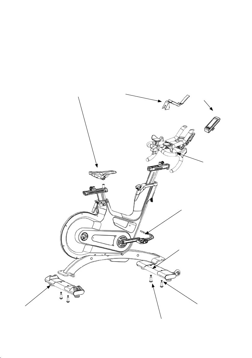
SPARE PARTS
Due to revisions, spare part order no. and specications may be subject to change.
For further information please contact your local distributor (p35) or visit www.indoorcycling.com.
1
24
3
5
6
7
8
10

33
ENG
SPARE PARTS
DESCRIPTION ITEM NUMBER
1 WATTRATE TFT DISPLAY 320-00-00011-01
2 COMPUTER BRACKET COVER 110-01-00056-01
3 HANDLEBAR ASSEMBLY 110-01-00037-01
4 SADDLE 120-01-00054-01
5 FRONT STABILIZER 140-02-00003-01
6 1 PCS. LEVELING FEET 900-10-00003-01
7 1 PCS. STABILIZER MOUNTING HARDWARE 190-01-00004-01
9 REAR STABILIZER 140-02-00002-01
10 PEDALS 150-01-00005-03

Version 1.0 2018 IC-LFIC8C1-01 Copyright by Indoor Cycling Group GmbH 2018 | www.indoorcycling.com
WARRANTY
ICG warrants that all new equipment will be free of manufacturing defects in workmanship and materials,
eective on the date of original assembly at its production facility. Parts repaired or replaced under the terms
of this warranty will be warranted for the remainder of the original warranty period only. ICG is obligated to
uphold its manufacturer warranty obligation so long as the product is used in the closed environment it was
designed for, Temperature range between 15ºC~40°C Celsius (59ºF~104°F) and max. 65% humidity (not near
a swimming pool or outdoors). Defects caused by obvious deliberate mechanical impact, inappropriate use
or undo handling of the product may cause the manufacturer’s warranty to become void. In order for the
manufacturer to uphold the warranty coverage, the customer (tness facility) is obligated to maintain and
service the product as per the manufacturer’s specications stated in the owner manual of each product.
5 YEARS WARRANTY: FRAME CONSTRUCTION AND WELDING
3 YEARS WARRANTY: POWDER COATING (PAINT CRACKS, CORROSION)
HANDLEBAR AND SEAT POST ASSEMBLY
(ALUMINUM PARTS AND PVC COATING)
DUAL BELT DRIVE SYSTEM
POWER SENSOR
BOTTOM BRACKET ASSEMBLY
FLYWHEEL AND HUB ASSEMBLY
CRANKS
PEDALS (EXCLUDED BINDING SYSTEM AND STRAPS)
INSERT SLEEVES FOR HANDLE BAR AND SEAT POST
BOWDEN CABLES (BRAKE ADJUSTMENT, EBRAKE ACTIVATION,
GAS DAMPER ACTIVATION CABLE SP &HB VERTICAL ADJUSTMENT)
BRAKE SYSTEM
GAS DAMPERS
FLIP LEVER ASSEMBLY
FOR HORIZONTAL AND VERTICAL ADJUSTMENT (HB & SP)
LEVELLING FEET
SHROUD AND TOP COVERS
1 YEAR WARRANTY: ELECTRONIC COMPONENTS
(COMPUTER, CABLE HARNESS, PCBS AND SENSORS, GENERATOR)
LITHIUM POLYMER (LIPO) BATTERY
SADDLE CONSTRUCTION (EXCLUDED STITCHING AND SADDLE SURFACE)
THE FOLLOWING WEAR ITEMS ARE EXCLUDED FROM WARRANTY:
Pedal straps, pedal binding system, saddle surface.

35
ENG
CORPORATE HEADQUARTERS
Columbia Centre III, 9525 West Bryn Mawr Avenue, Rosemont, Illinois 60018 • U.S.A.
847.288.3300 • FAX: 847.288.3703
Service phone number: 800.351.3737 (toll-free within U.S.A., Canada)
Global Website: www.lifetness.com
INTERNATIONAL OFFICES
AMERICAS
NORTH AMERICA
LIFE FITNESS, INC.
Columbia Centre III
9525 West Bryn Mawr Avenue
Rosemont, IL 60018 U.S.A
Telephone: (847) 288 3300
Fax: (847) 288 3703
Service Email:
customersupport@lifetness.com
Service Website:
www.lifetness.com/parts
Sales/Marketing Email:
commercialsales@lifetness.com
Operating Hours: 7:00 am-6:00 pm (CST)
BRAZIL
LIFE FITNESS BRASIL
Av. Rebouças, 2315
Pinheiros
São Paulo, SP 05401-300
BRAZIL
SAC: 0800 773 8282 option 2
Telephone: +55 (11) 3095 5200 option 2
Service Email: suportebr@lifetness.com
Sales/Marketing Email:
vendasbr@lifetness.com
Service Operating Hours:
8:30 - 17:30 (BRT) (Monday-Friday)
Store Operating Hours:
9:00 -18:30 (BRT) (Monday-Friday)
10:00 - 14:00 (BRT) (Saturday)
LATIN AMERICA & CARIBBEAN*
LIFE FITNESS INC.
Columbia Centre III
9525 West Bryn Mawr Avenue
Rosemont, IL 60018 U.S.A
Telephone: (847) 288 3300
Fax: (847) 288 3703
Service Email:
customersupport@lifetness.com
Sales/Marketing Email:
commercialsales@lifetness.com
Operating Hours: 7:00am-6:00pm (CST)
EUROPE, MIDDLE EAST,
& AFRICA (EMEA)
NETHERLANDS & LUXEMBURG
LIFE FITNESS ATLANTIC BV
Bijdorpplein 25-31
2992 LB Barendrecht
THE NETHERLANDS
Telephone: (+31) 180 646 666
Service Email:
service.benelux@lifetness.com
Sales/Marketing Email:
marketing.benelux@lifetness.com
Operating Hours: 9:00h-17:00h (CET)
UNITED KINGDOM
LIFE FITNESS UK LTD
Queen Adelaide
Ely, Cambs, CB7 4UB
Telephone:
General Oce (+44) 1353.666017
Customer Support (+44) 1353.665507
Fax: (+44) 1353.666018
Service Email: uk.support@lifetness.com
Sales/Marketing Email:
life@lifetness.com
Operating Hours:
General Oce: 9.00am - 5.00pm (GMT)
Customer Support: 8.30am - 5.00pm (GMT)
GERMANY
INDOOR CYCLING GROUP
Happurger Strasse 84-88
90482 Nuernberg
GERMANY
Telephone: +49 (0) 911 / 544450
Service Email: [email protected]
Sales/Marketing Email:
Operating Hours: 08.30 -16.30h (CET)
AUSTRIA & SWITZERLAND
LIFE FITNESS EUROPE GMBH
Neuhofweg 9
85716 Unterschleißheim
GERMANY
Telephone:
+49 (0) 89 / 31775166 Germany
+43 (0) 1 / 6157198 Austria
+41 (0) 848 / 000901 Switzerland
Service Email:
kundendienst@lifetness.com
Sales/Marketing Email:
vertrieb@lifetness.com
Operating Hours: 08.30 -16.30h (CET)
SPAIN
LIFE FITNESS IBERIA
C/Frederic Mompou 5,1º1ª
08960 Sant Just Desvern Barcelona
SPAIN
Telephone: (+34) 93.672.4660
Fax: (+34) 93.672.4670
Service Email:
servicio.tecnico@lifetness.com
Sales/Marketing Email:
info.iberia@lifetness.com
Operating Hours:
9.00h-18.00h (Monday-Thursday)
8.30h-15.00h (Friday)
BELGIUM
LIFE FITNESS BENELUX NV
Parc Industrial de Petit-Rechain
4800 Verviers
BELGIUM
Telephone: (+32) 87 300 942
Service Email:
service.benelux@lifetness.com
Sales/Marketing Email:
marketing.benelux@lifetness.com
Operating Hours: 9.00h -17.00h (CET)
ALL OTHER EMEA COUNTRIES &
DISTRIBUTOR BUSINESS EMEA*
Bijdorpplein 25-31
2992 LB Barendrecht
THE NETHERLANDS
Telephone: (+31) 180 646 666
Service Email:
EMEAServiceSupport@lifetness.com
ASIA PACIFIC (AP)
JAPAN
LIFE FITNESS JAPAN, LTD
4-17-33 Minami Aoyama 1F/B1F
Minato-ku - Tokyo 107-0062
Japan
Telephone: (+81) 0120.114.482
Fax: (+81) 03-5770-5059
Service Email: service.l@lifetness.com
Sales/Marketing Email:
sales@lifetnessjapan.com
Operating Hours: 9.00h-18.00h (JAPAN)
HONG KONG
LIFE FITNESS ASIA PACIFIC LTD
32/F, Global Trade Square
21 Wong Chuk Hang Road
Hong Kong
Telephone: (+852) 2575.6262
Fax: (+852) 2575.6894
Service Email: Service.HK@lifetness.com
Sales/Marketing Email: hongkong.sales@
lifetness.com
Operating Hours: 9.00h-17.00h
ALL OTHER ASIA PACIFIC COUNTRIES
& DISTRIBUTOR BUSINESS
ASIA PACIFIC*
32/F, Global Trade Square
21 Wong Chuk Hang Road
Hong Kong
Telephone: (+852) 2575.6262
Fax: (+852) 2575.6894
Service Email: Service.AP@lifetness.com
Sales/Marketing Email:
Marketing.HK.Asia@lifetness.com
Operating Hours: 9.00h-17.00h
* Also check www.lifetness.com for local representation or distributor/dealer

Manufactured by: Indoor Cycling Group® GmbH
Happurger Str. 86 90482 Nuernberg Germany
EMAIL: [email protected]OM
WEBSITE: WWW.INDOORCYCLING.COM
© 2018 Indoor Cycling Group
CAUTION.
READ ALL PRECAUTIONS AND INSTRUCTIONS IN THIS MANUAL
BEFORE YOU BEGIN USING THIS EQUIPMENT. PLEASE KEEP
THIS MANUAL FOR FUTURE REFERENCE. IMPROPER ASSEMBLY,
SET UP, USE OR MAINTENANCE MAY VOID THE WARRANTY.