
ERG8000/ERG9
080
DELUXE INDOOR CYCLE TRAINER
WITH CURVE-CRANK TECHNOLOGY
®
OWNER’S MANUAL
This product is intended for indoor, home use only and is not to be used in a commercial setting.

This page is left blank intentionally
ERG8000/ERG9080
Page
1
PLEASE KEEP THESE INSTRUCTIONS FOR FUTURE USE & REFERENCE.
DO NOT DISCARD.
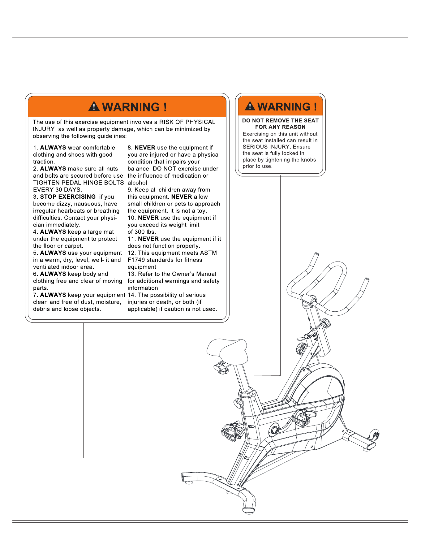
WARNING: SERIOUS INJURIES AND EVEN DEATH CAN OCCUR IF THE PROPER SAFETY PRECAUTIONS
ARE NOT FOLLOWED.
The diagram below highlights and reviews many of the important Safety and Warning labels also found on the unit.
Please ensure any user of the unit familiarizes themselves with this Safety and Warning guidelines before use.

ERG8000/ERG9080
Page
2
Before you undertake any exercise program, please be sure to
consult with your doctor.
Frequent strenuous exercise should be approved by your
doctor and proper use of your product is essential.
Excessive or incorrect training may result in health injuries.
Please read this manual carefully before commencing the
assembly of your product or starting to exercise.
• Please keep all children away from this item when in use.
Do not allow children to climb or play on this item when it
is not in use.
• Supervise teenagers while they use this unit.
• For your own safety, always ensure that there are at least
3 feet of free space in all directions around your product
while you are exercising.
• Regularly check to see that all nuts, bolts and ttings are
securely tightened. Periodically check all moving parts for
obvious signs of wear or damage.
• Any adjustment devices that could interfere with the user’s
movement of this unit should not be left projecting.
• Clean only with a damp cloth, do not use solvent
cleaners. Lubricate the moving parts of your unit every 30
days with a silicone-based grease or product.
If you are in any doubt, do not use your product; contact
CUSTOMER SUPPORT.
• Before use, always ensure that your product is positioned
on a solid, hard-at surface.
• Do not place on carpet. If necessary, use a rubber mat
underneath to reduce the possibility of slipping.
• Always wear appropriate clothing and footwear such as
training shoes when exercising. Do not wear loose clothing
that could become caught in moving parts during exercise.
• Do not use this unit if it is not functioning properly or if it is
not fully assembled.
• Do not use this unit for commercial purposes. This unit is
for home use only.
• Before use, you must read and understand all instructions
& warnings stated in this Owner’s Manual as well as
posted on the equipment.
• It is the facility owner’s responsibility to properly instruct
users on the proper operation of the equipment and to
warn them of the potential hazards.
• If at any time during exercise you feel faint, dizzy or
experience pain, stop and consult your physician.
Your product is intended for use in clean dry conditions. You
should avoid storage in excessively cold or damp places as
this may lead to corrosion and other related problems.
If you have any questions concerning the assembly of your
item or if any parts are missing, please DO NOT RETURN
THE ITEM TO THE STORE OR CONTACT THE
RETAILER.
Our dedicated customer service sta can help you with
any questions you may have regarding the assembly of this
unit and can also mail you replacement parts.
Customer Support is open 9:00 a.m. to 5:00 p.m. (Pacic
Time) Monday through Friday.
Please contact us by any of the following means :
Body Flex Sports, Inc.
21717 Ferrero Parkway, Walnut, CA 91789
Telephone: 1 (888) 266 - 6789
Fax: 1 (909) 598 - 6707
Email: info@bodyexsports.com
Body Flex Sport warrants your product is free of any defects in
workmanship and materials for a period of 1 year for the frame
and 90 days on all parts if the item is used for the
intended purpose, properly maintained and not used
commercially.
Any alterations or incorrect assembly of the product will void
this warranty.
Proof of purchase must be presented for any warranty
validation (no exceptions). This warranty applies to the original
purchaser only and is not transferable.
This warranty covers parts damaged due to defect in work-
manship and materials; it does not cover abuse or damages
caused during use, storage or assembly. During the warranty
period, Body Flex Sport reserves the right to:
1. provide replacement parts to the purchaser in an eort to
repair the item.
2. repair the product returned to our warehouse
(at purchaser’s cost).
3. replace the product if neither of the two previously
- Ruler with both Metric and English measurements
- 2 x Adjustable Wrenches
- 1 x Philips (”Crosshead”) Screw Driver
Your product is suitable for users weighing:
300 pounds or less
General Information
Safety Storage and Use
Questions
Customer Support
Warranty
Assembling Tools
Weight Limit

ERG8000/ERG9080
Page
3
Before Assembly
1. Take a few minutes to familiarize yourself with the parts and hardware included with your product.
2. The assembly may require two people.
3. Check the frame for any damage and check any wiring (if present) for rips or tears. If you detect damage, rips, or
tears, please contact our Customer Support Team before beginning any assembly.
4. Make sure all the hardware needed is included.
5. It is very important to follow the assembly instructions correctly and to make sure all parts are attached correctly and
rmly tightened when the assembly process is complete.
6. Parts that are not tightened correctly will seem loose and can cause irritating noises and will cause damage to the
equipment.
Tools Required For Assembly
WARNING
PLEASE NOTE : Many of the parts and hardwares listed on the parts list are already pre-assembled or
installed on the unit.
Tool Description/Purpose
Ruler (with both Metric and English measurements)
QTY: 1
Use to measure the length or size of hardware including
bolts to ensure you are using the correct part.
Adjustable or at wrenches
QTY: 2
Use to securely install parts including nuts and bolts.

ERG8000/ERG9080
Page
4
Part Listing
The following parts list describes all of the parts illustrated in the exploded diagram on the following page.
PLEASE NOTE: most of these parts are already pre-assembled on your unit.
# Description
01 Front Stabilizer
02 Nut (M8)
03 Foot Pad
04 End Cap for Stabilizer
05 Screw (M6x12 mm)
06 Bearing (608ZZ)
07 Transport wheel
08 Screw(M6x15 mm)
09 Screw (M8x20 mm)
10 Spring Washer (M8)
11 Washer (M8)
12 Rear Stabilizer
13 Knob (M16x27 mm)
14 Sleeve (40x80-30x70 mm)
15 Brake Block
16 Screw (M5x7 mm)
17 Brake Cable
18 Bolt (M6x10 mm)
19 Brake Handle
20 Washer (M8)
21 Spring
22 Cable Base
23 Nylon Nut
24 Hex Bolt (M6x10 mm)
25 Washer (M6)
26 Bearing (6001-2RS)
27 Idle Pulley
28 Wave Washer (M10)
29 Seat
30 Seat Slider
31 Seat Post
32 End Cap (25x50 mm)
33 Washer (M10)
34 Knob (M10x32 mm)
35 Cover
36 Sleeve (30x70-20x60 mm)
37 Crank Plug
38 Nut (M10)
39L/R Crank
40L/R Pedal
41 Screw (ST4.2x16 mm)
42 Screw (ST4.2x19 mm)
43L/R Left/Right Shroud
44 C Clip (D17)
45 Bearing (6004-2RS)
46 Bushing (φ25x20.2xφ5.5 mm)
47 Magnet
48 Belt Wheel
49 Middle Axle
50 Bolt (M6x16 mm)
51 Belt
52 Tension Knob
53 Spring Washer (M6)
54 Washer (M6)
55 Clip Ring
56 Magnet
57 Magnet Holder
58 Magnet Plate
59 Magnet Plate Shaft
60 Screw (ST3x10 mm)
61 Spring
62 Brake Pad
63 Brake Pad Holder
64 Screw (M6x16 mm)
65 Brake Connected Plate
66 Nut (M12)
67 Handlebar Cover
68 Bolt (M6x50 mm)
69 Bolt (M8x45 mm)
70 Nut (M12)
72 Flywheel
73 Flywheel Axle
74 Handlebar Post
75 Screw (M5x8 mm)
76 Nylon Nut (M8)
77 Nut (M12)
78 Handlebar
79 Idler Connecting Rod
80 Nut (M10)
81 Main Frame
82 Washer (M5)
83 Screw (M5x16 mm)
84 Bolt (M8x16 mm)
85 PU Washer
86 Tension Knob Bracket
87 Wave Washer (M17)
88 Washer (M5)
89 Shroud Cover
A Allen Wrench
B Spanner
# Description
ERG8000/ERG9080
Page 5
6
7
6
5
8
6
7
6
5
8
9
10
11
4
2
3
1
4
13
4
12
4
9
10
11
A
S6
B
S13-S15
2
2
3
2
3
9
10
11
14
15
16
16
17
18
19
20
21
22
23
23
23
23
24
25
26
27
26
28
29
32
31
30
32
33
34
35
36
44
45
37
38
3
9L
3
9R
38
50
49
48
13
45
46
52
50
53
54
55
56
57
50
53
54
55
60
61
58
59
51
47
61
64
64
62
63
65
74
75
81
86
82
83
37
40L
4
0R
85
86
88
88
87
2
3
89
41
41
42
42
4
3L
42
42
42
41
89
4
3R
42
41
42
42
41
11
26
26
66
70
73
77
66
72
78
11
11
10
10
67
69
84
76
79
68
80
77
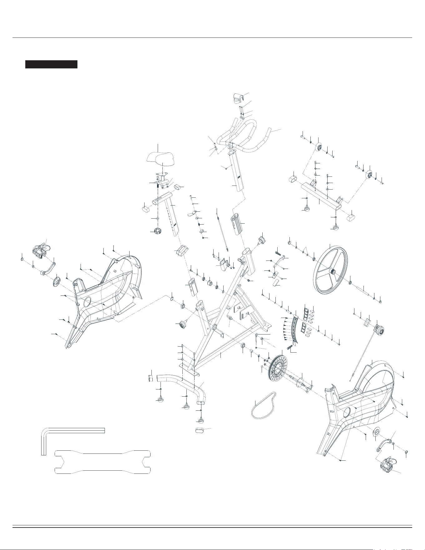
Exploded View
The following diagram is provided to help you familiarize yourself with the parts and hardware that will be used during the
assembly process.
: : Not all of the parts and hardware you see here will be used while you are assembling the machine
because some of these items are already pre-installed. Please use this page only as a reference guide for parts and
hardware.
PLEASE NOTE
ERG8000/ERG9080
Page
6
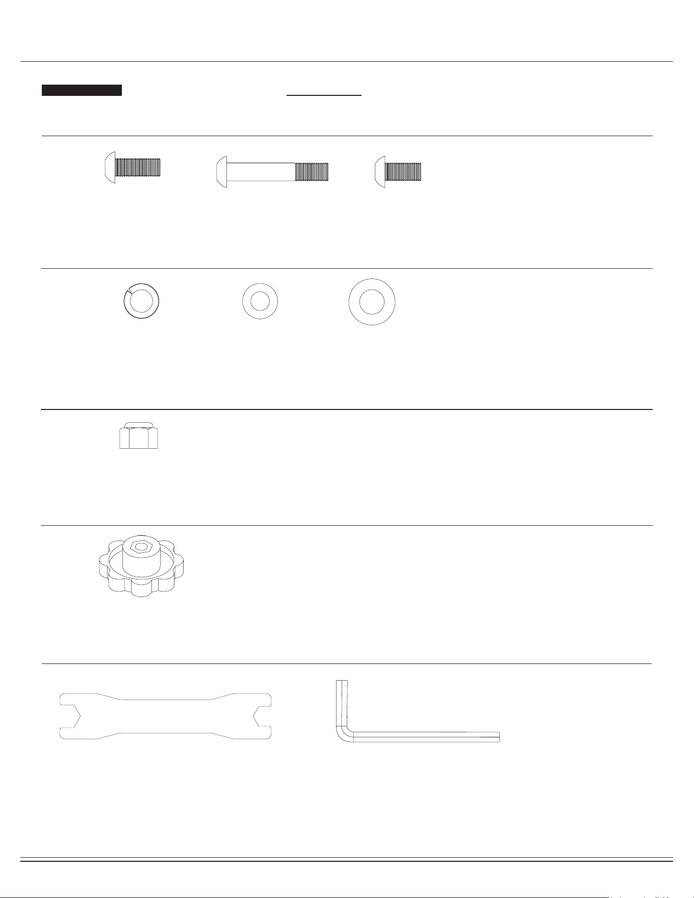
Hardware and Tool List
Bolts
Washers
Nuts
Others
Tools (Included)
The following hardware is used to assemble your unit. Please take a moment to familiarize yourself with these items.
PLEASE NOTE: Most of these parts are already pre-assembled on your unit. Do not be alarmed if you see parts on this
page that are not included in your hardware packet.
#10 Spring Washer (M8)
[7 pieces]
#11 Washer (M8)
[10 pieces]
Pre-assembled [3 pieces]
#33 Washer (M10)
[1 piece]
#9 Screw (M8x20 mm)
[4 pieces]
#84 Bolt (M8x16 mm)
[1 piece]
#69 Bolt (M8x45 mm)
[2 pieces]
#A Allen Wrench
[1 piece]
#B Spanner
[1 piece]
#76. Nylon Nut (M8)
[3 pieces]
#34 Knob (M10x32mm)
[1 piece]
Pre-assembled
ERG8000/ERG9080
Page
7
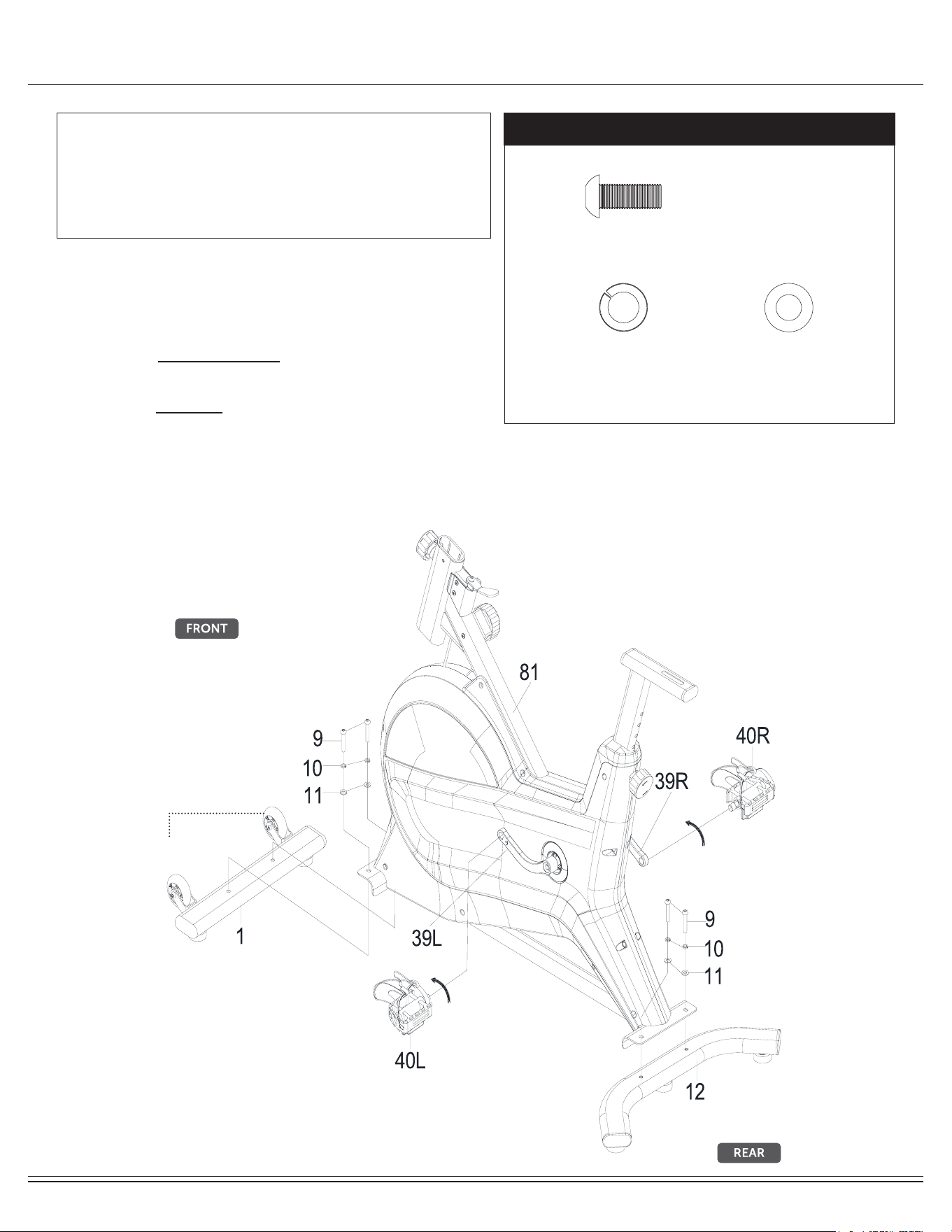
Assembly STEP 1
Attach the Front & Rear Stabilizer (No.1 & 12) to the Main Frame
(No.81) using 4 Screws (No.9), 4 Spring washers (No.10) and 4
Washer (No.11).
Attach Left Pedal (No. 40L) to Left Crank (No.39L). Turn the Left
Pedal (No. 40L) counter-clockwise to lightly tighten it.
Attach Right Pedal (No.40R) to Right Crank (No.39R). Turn the Right
Pedal (No.40R) clockwise to lightly tighten it.
Note:
The Pedals (No.40L/R) are marked "L"and "R" for Left and Right.
Make sure you attach the correct pedal to the corresponding
crank.
Hardware Required
Front Roller
NOTE BEFORE STARTING THE ASSEMBLY PROCESS :
To avoid misalignment due to over-tightening, please do not use a
wrench and use only hand-tightening for now to ensure
easy assembly.
Wrench-tightening should be performed after all parts are assembled
to ensure all nuts, bolts, and parts are tightly secured before use.
#10 Spring Washer (M8)
[4 pieces]
#11 Washer (M8)
[4 pieces]
#9 Screw (M8x20 mm)
[4 pieces]
ERG8000/ERG9080
Page
8
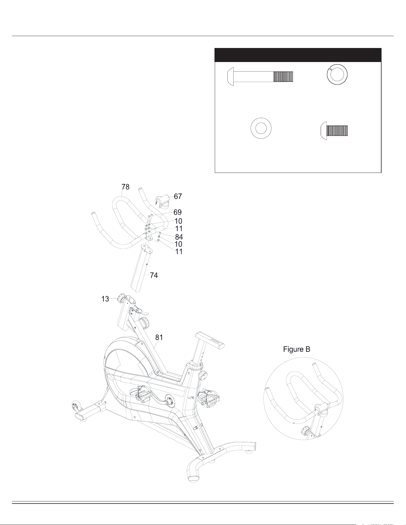
Assembly STEP 2
Loosen and pull out the Knob (No.13), then insert the Handlebar post
(No.74) into Mainframe (No.81) at the desired position. Put back and
secure with the Knob (No.13).
Attach the Handlebar (No.78) to Handlebar Post (No.74) using 2 Bolts
(No.69), 1 Bolt (No.84), 3 Spring washers (No.10) and 3 Washers
(No.11). Then attach the Cover (No. 67) on the Handlebar (No.78)
(Figure B)
Hardware Required
#10 Spring Washer (M8)
[3 pieces]
#11 Washer (M8)
[3 pieces]
#69 Bolt (M8x45 mm)
[2 pieces]
#84 Bolt (M8x16 mm)
[1 piece]
ERG8000/ERG9080
Page
9
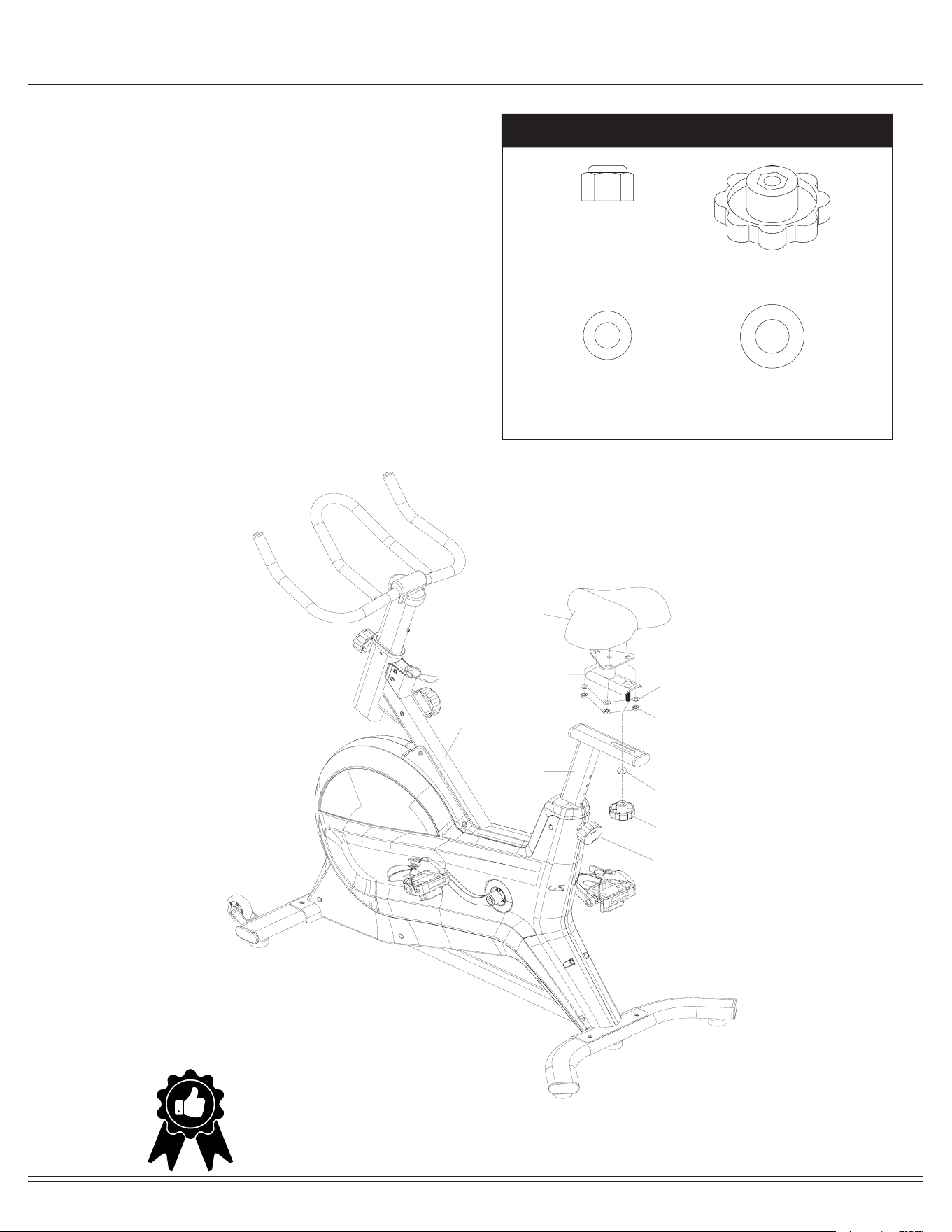
Assembly STEP 3
Hardware Required
Loosen Washer (No. 11) and Nylon nut (No. 76) from Seat (No. 29),
attach Seat (No. 29) to Seat slider (No. 30) with Washer (No. 11)
and Nylon Nut (No. 76).
Attach Seat slider (No. 30) to Seat post (No. 31) with Washer (No. 33)
and the Knob(No. 34).
Adjust and secure the Seat (No. 29) with the Knob (No. 13) and Knob
(No. 34) at desired position.
Now that the assembly steps are completed, please tighten all
the bolt and nuts securely in place using the tools provided
81
13
30
31
33
34
11
76
29
#11 Washer (M8)
Pre-assembled [3 pieces]
#33 Washer (M10)
[1 piece]
#76. Nylon Nut (M8)
[3 pieces]
#34 Knob (M10x32mm)
[1 piece]
Pre-assembled
THE ASSEMBLY PROCESS IS NOW COMPLETE.
However, for your own safety, please make sure to read this entire Owner’s Manual which includes
safety instructions and warnings, as well as any safety/warning labels axed to the product before use.
For your safety , please visually and functionally inspect and test the unit after assembly is complete.
ERG8000/ERG9080
Page
10
Tension Adjustment
A. Adjusting the Tension:
Increasing or decreasing the tension allows you to add variety to your
workout sessions. To increase the tension, rotate the TensionKnob
(No.52) (“+”) clockwise (Arrow A).
To decrease the tension, turn the Tension Knob (No.52) (“-”)
counter-clockwise (Arrow B).
B. Emergency Brake Function:
The Brake Handle (No.19) is an emergency brake. Use this safety
feature in a situation when you would need to get o the bike or stop
the bike’s ywheel. During exercise, press down rmly on the Brake
Handle (No.19) to stop the bike immediately.
52
19
8
7
6
5
4
A
B
8
7
6
5
4
ERG8000/ERG9080
Page
11
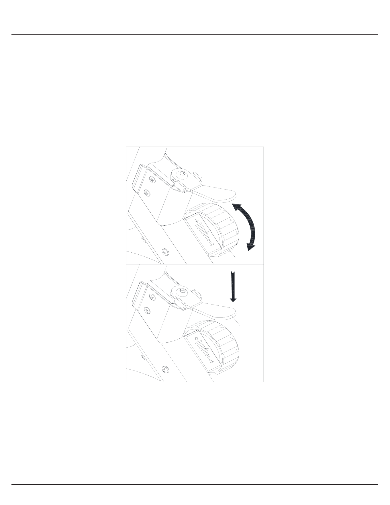
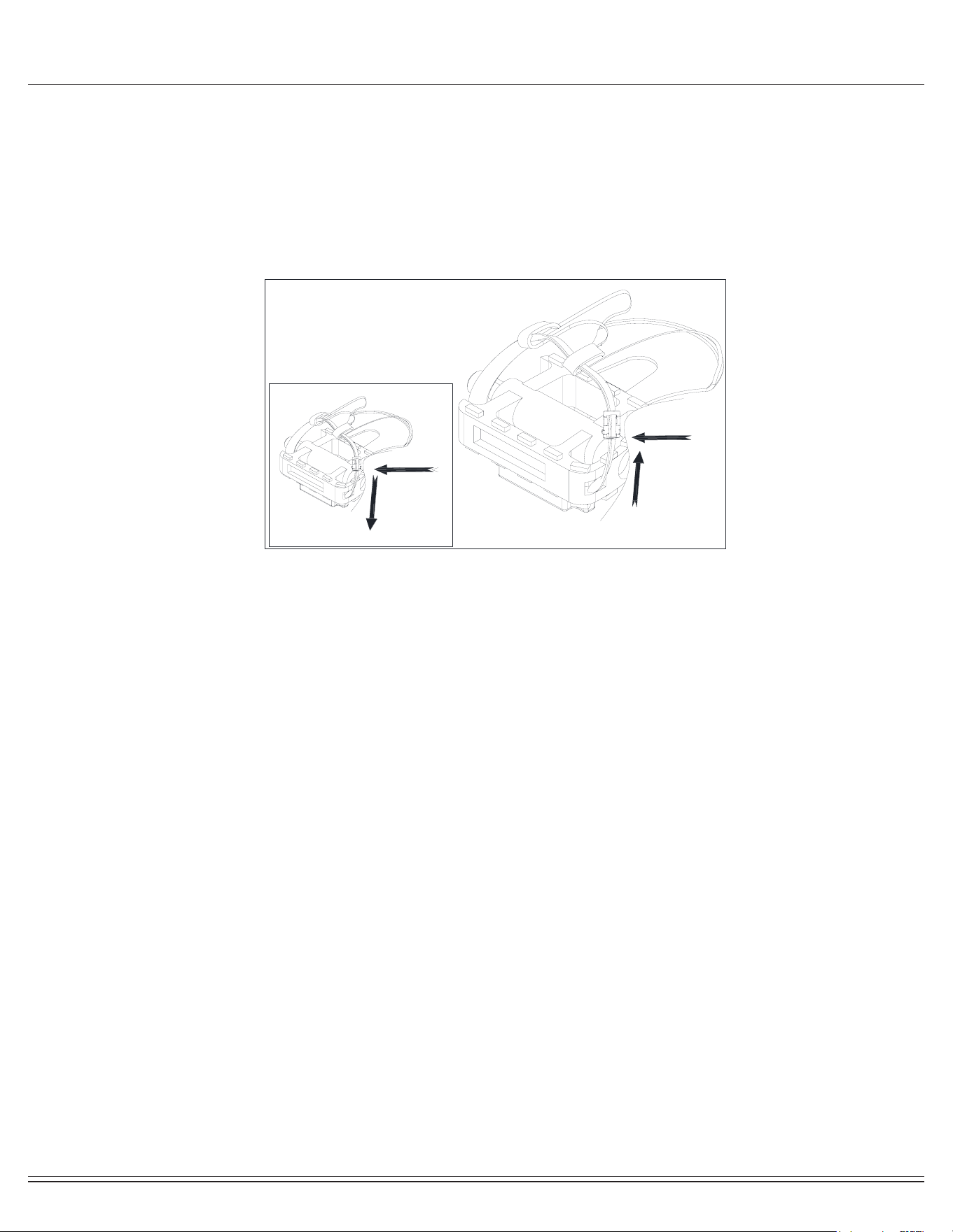
Pedal Strap AdjustmentUsage
When the pedal is tight, press the buckle and pull the strap up to
loosen the strap (Figure A).
When the pedal is loose, press the buckle and pull the strap
down to fasten the strap (Figure B).
Figure B Figure A
ERG8000/ERG9080
Page
12
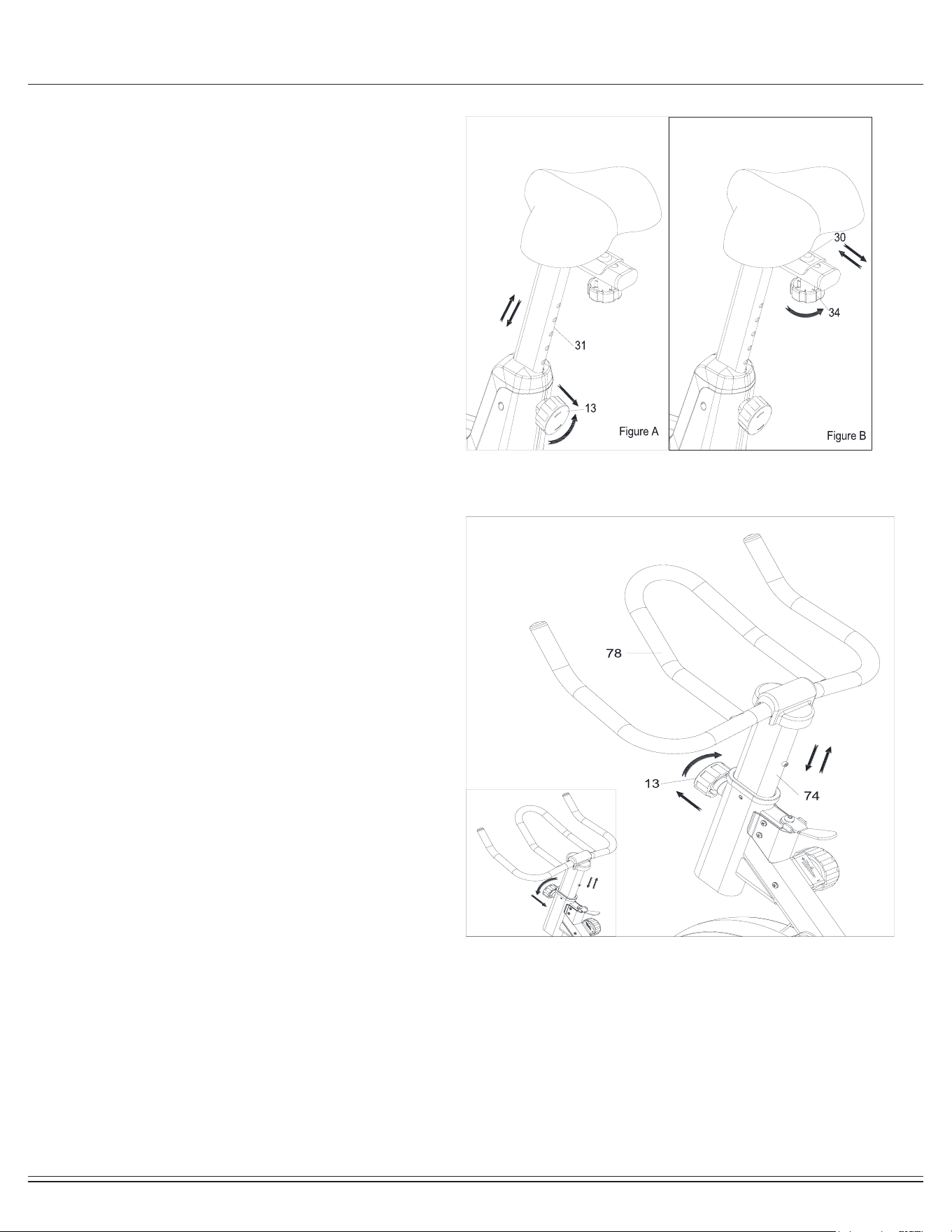
Seat and Handlebar Adjustment
The seat of this bike is fully adjustable as it moves Up, Down,
Forward, Backward.
A. To adjust the height of the Seat Post (No.31), loosen and pull
out the Knob (No.13), then raise or lower the seat to the desired
height. Once adjusted, re-insert and tighten the Knob (No.13) to
secure the seat
in place (Figure A).
B. To adjust the seat forward and backward, loosen Knob
(No.34), then slide the Seat Slider (No.30) to the desired
position. Once positioned, tighten the Knob (No.34) to secure the
Seat Slider (No.30) in place (Figure B).
C. To adjust the height of Handlebar (No.78), loosen and pull
on the Knob (No.13), then slide the Handlebar Post (No.74) up
or down to the desired height. Once adjusted, tighten the Knob
(No.13) to secure the Handlebar Post (No.74) in place.
ERG8000/ERG9080
Page
13
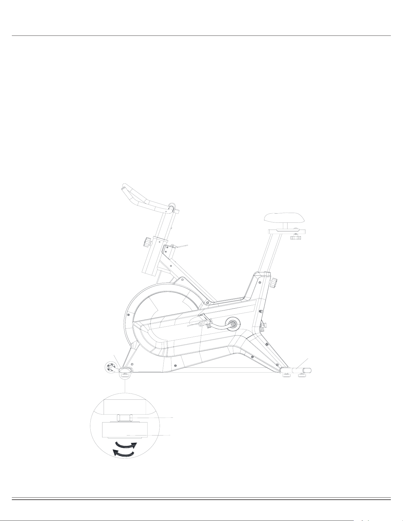
Balance Adjustment
To achieve a smooth and comfortable experience, you must
ensure that the bike is stable.
During use, if you notice that the bike is unbalanced, you can
adjust the Foot Pads (No.3) located beneath the Front & Rear
Stabilizers (No.1 & 12).
To adjust, use the Spanner (Tool B) to loosen the Hexagon Nut
(No.2) by turning it clockwise. With the nut loosened, rotate the
Foot Pads (No.3) until it sits level with the surface that the bike is
on.
When you have nished adjusting the Foot Pads (No.3), re-tight-
en the Hexagonal Nut (No.2) by turning it counter-clockwise
using Spanner (Tool B). If needed, repeat this process to adjust
the remaining Foot Pads (No.3).
A
B
3
12
1
2
ERG8000/ERG9080
Page
14
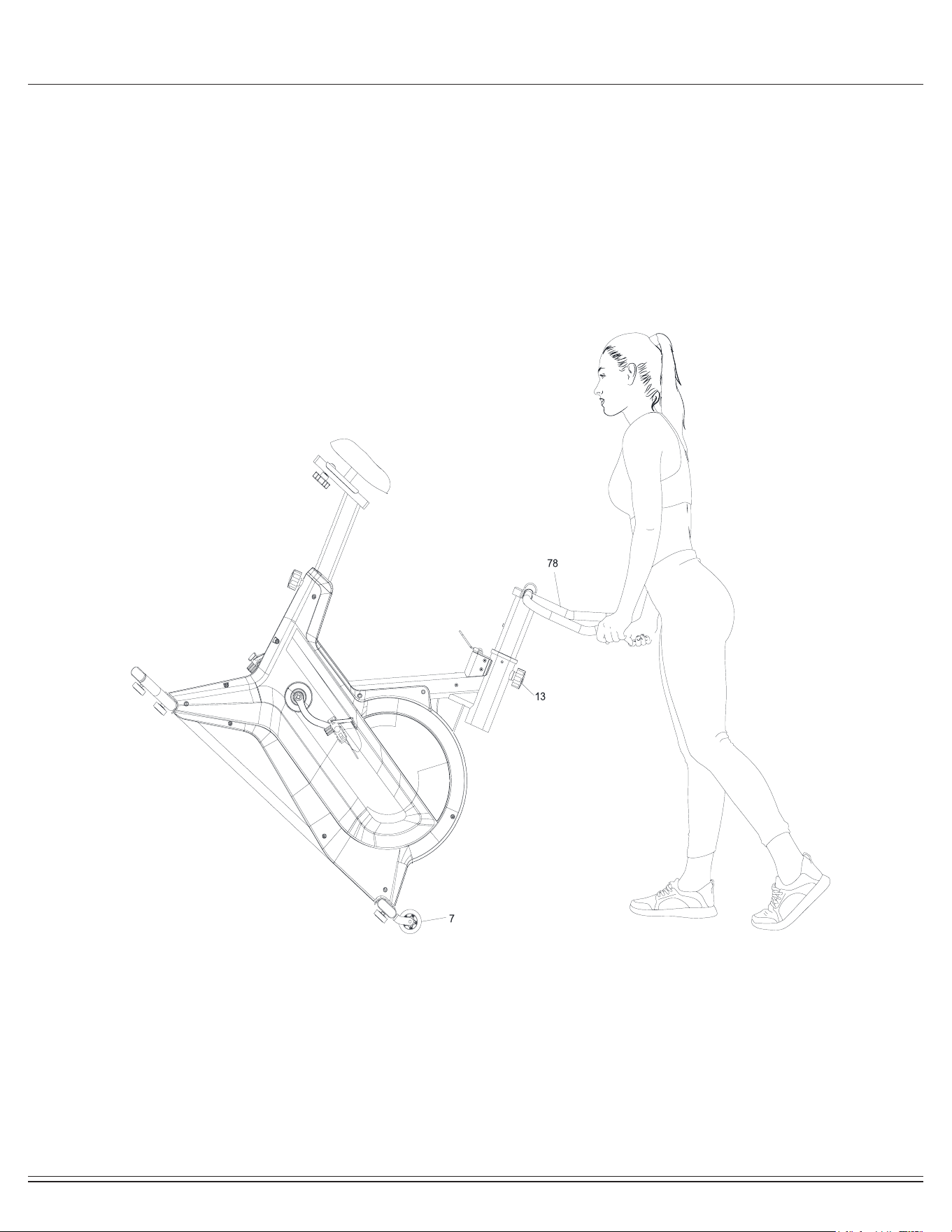
How To Move The Bike
To move the bike, rst ensure that the Handlebar (No.78)
is properly secured. If the Handlebar (No.78) is loose, tighten the
knob (No.13) to secure it.
Next, stand at the front of the bike so that you’re directly in
front of the Handlebar (No.78). Firmly grasp and hold each side
of the Handlebar (No.78), place one foot on the front base and
tilt the bike towards you until the Transport Wheels (No.7) on the
front base touch
the ground. With the wheels on the ground, you
can transport the bike to the desired location with ease.

ERG8000/ERG9080
Page
15
Safety and Maintenance
• Make sure all nuts, bolts, and screws are tightened prior to use.
• Be sure that all adjustment locking devices and safety devices are properly engaged prior to use!
• Never over-tighten the above-mentioned devices and parts to avoid damage to the unit.
• Check for loose parts and components and make proper adjustments prior to use.
• Check to see if there are any tears or bends in the welding or metal prior to use. If tears or bends are found,
DO NOT use the unit and contact our CUSTOMER SUPPORT.
• Extreme care must be taken to not allow your feet, ngers, hair, clothing, and/or any loose items to be snagged into
any portion of the bike when the unit is in motion. Failure to follow these instructions could result in serious injury,
including the loss of ngers.
• Always wait for the pedals and other moving parts (which can gain great momentum during riding) to come to a
complete stop before dismounting the unit to avoid serious injury.
• Please review all safety instructions and warnings in this entire Owner’s Manual, as well as any safety/warning labels
axed to the product before use.
• To avoid rust or corrosion to the ywheel caused by moisture and sweat, we advise wiping and drying the ywheel
and surrounding parts with a dry absorbent towel after each workout session.
• Do not use solvent cleaners. If you are in any doubt, do not use your cleansing product and contact CUSTOMER
SUPPORT.
• When the bike is not in use, the resistance should be left loose, NOT tightened down against the ywheel. You can
do this with the easy-to-adjust tension knob. This will ensure longer life of the Friction Belt. mechanism from working
properly. Please contact our CUSTOMER SUPPORT if you have questions regarding the cleaning of your bike.
• The specic Parts on your unit which may see possible signs of wear after prolonged use are listed as
follows (please check these parts before each use):
Knob (#13 & #34), Brake Handle (#19), Left/Right Pedals(40L/40R)..
• For any replacement warning labels, please contact our CUSTOMER SUPPORT at
1 (888) 266-6789 or 1 (909) 598-9876, or mail in a written request to:
Body Flex Sports, Inc.
21717 Ferrero Parkway
Walnut, CA 91789
More detailed information about how to reach our CUSTOMER SUPPORT may be found on Page 2 of the
Owner’s Manual under the “CUSTOMER SUPPORT” section.
Safety & Warning
Maintenance & Care
ERG8000/ERG9080
Page
16
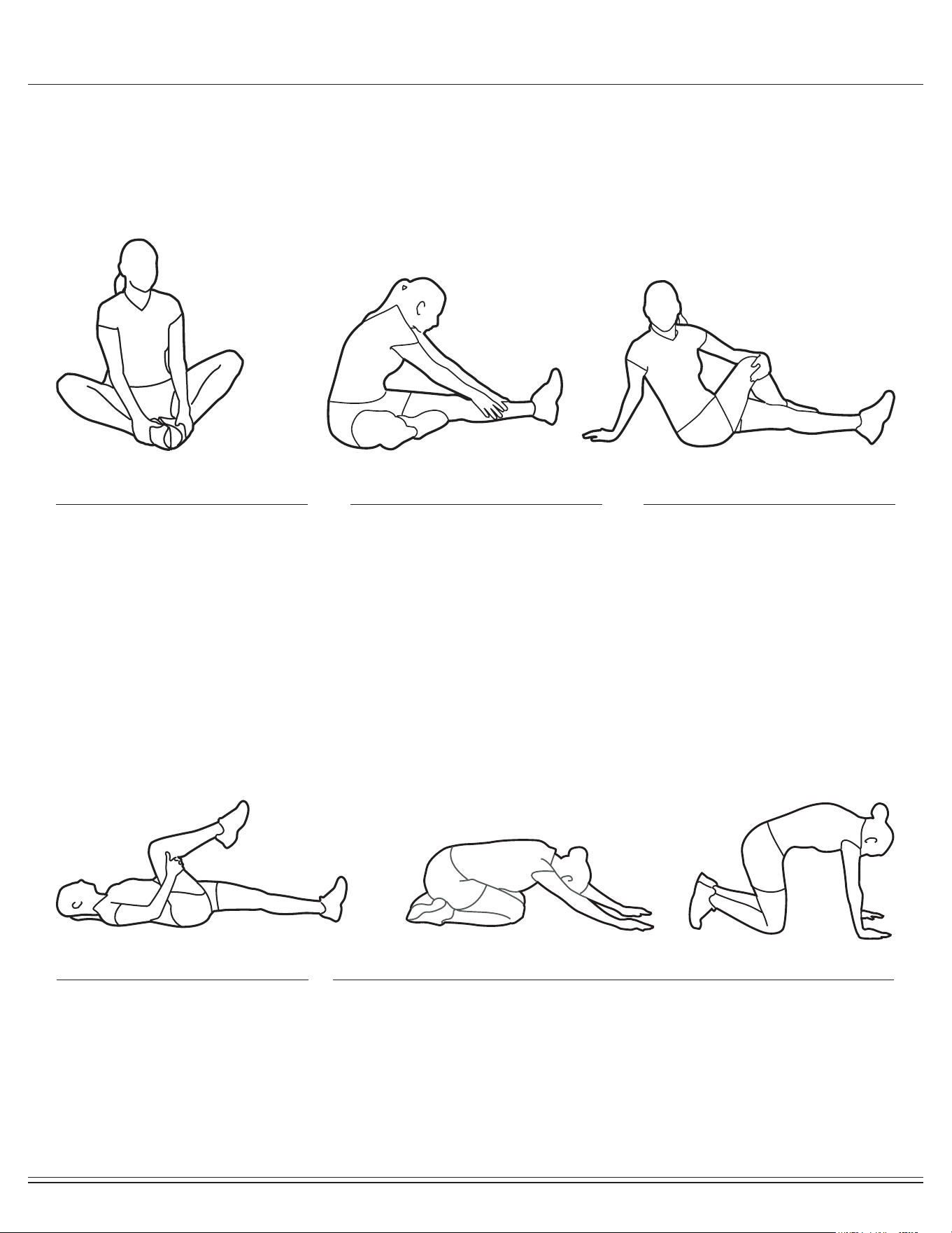
Warm-Up Instructions
1. Sit with your knees exed and
soles of feet together.
2. Hold your ankles and bend
at your hips (keep your back
straight) as you press your
knees toward the oor with your
elbows.
1. Lie on your back and raise
your right leg as you clasp both
hands under the back of the
knee. Keep your left leg straight.
2. Gently pull your right leg toward
your trunk without
raising your upper body. Switch
leg positions and repeat.
1. Sit with your left leg extended
and bend your right leg at the
knee as you place the sole of
your right foot against the inner
thigh of your extended leg.
2. Flex the foot of your extended
leg (toes pointed toward
ceiling) and gently bend forward
from your hips; keep your back
straight.
3. Reach your hands on your
extended leg as far as possible
and then switch legs and repeat.
1. Assume the depicted position on your hands and knees. Stretch your
hands out in front of you and then slowly start to pull them back in toward
your body as you tuck your chin and arch your back upward.
2. Return to the starting position slowly.
1. Sit with your leg extended and
bend your right knee as you
cross your right leg over your
left leg. Your right foot of your
extended leg foot should be at
on the oor alongside your left
knee.
2. Place your left arm on the
outside of your right leg and pull
against that leg while twisting
your trunk as far as possible to
the right. Place your right hand
on the oor behind your but-
tocks. Reverse leg positions and
repeat.
Before use, you must read and understand all instructions & warnings stated in this Owner’s Manual as well as posted
on the equipment. Before beginning any exercise program including the following exibility exercises, please consult with
your physician.
The following exibility exercises are provided to you as a means to prevent injury while you are exercising. A proper
warm-up routine decreases the chance of injuring your muscles while you are exercising. Please take the time to do these
exibility exercises before and after each time you exercise.
Groin Stretch
Groin Stretch
Hamstring Stretch
Trunk Flexion, Prone
Trunk Twister
ERG8000/ERG9080
Page
17
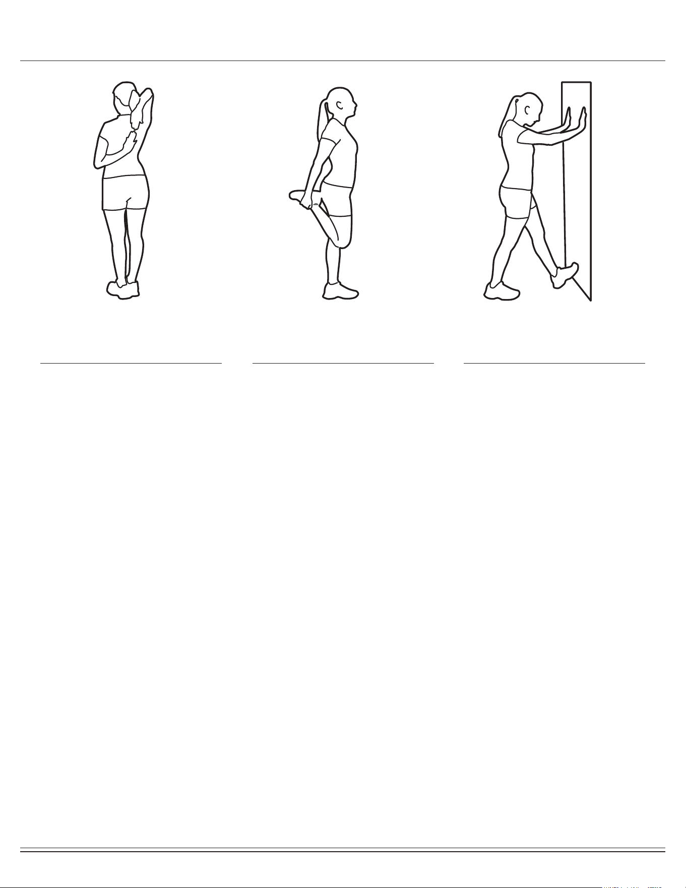
Warm-Up Instructions
1. Bring your right hand over your
right shoulder to the
upper back and bring your left
hand under your left shoulder to
the upper back.
2. Try to reach your ngertips. If
you are not able to reach your
ngertips, use a towel as an
extension of your hands and
gently pull one hand toward the
other.
Reverse arm positions and
1. Stand on your left leg and hold
onto a support with your left
hand.
2. Flex your right leg behind you,
grasp your ankle or foot with
your right hand and pull your
foot toward your buttocks. Keep
your back straight and right
knee pointed down.
Repeat on the other leg.
1. Place both hands against a wall
to aid your balance. Press the
ball of your left foot against the
wall and keep the heel of the
same foot rested on the oor
(make sure your left knee is
bent).
2. Slowly start to straighten your
left knee and you will feel the
muscles in your left calf stretch.
Switch leg positions and repeat.
Shoulder Stretch Quadriceps Stretch Calf Twister

THANK YOU FOR YOUR PURCHASE
MODEL NO.: ERG8000/ERG9080
Please ll in the information below and keep this manual
along with your sales receipt as proof of purchase.
Serial Number :
Date of Purchase :
Retailer :
Body Flex Sports, Inc.
21717 Ferrero Parkway
Walnut, CA 91789
Phone : 1 (888) 266-6789
Fax : 1 (909) 598-6707
Email : info@bodyexsports.com
Ver. 06/20/2019 Printed in China