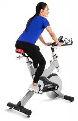

XIC600 Indoor Cycle
OWNER’S MANUAL

3
TABLE OF CONTENTS
5 IMPORTANT SAFETY INSTRUCTIONS
6 IMPORTANT OPERATION INSTRUCTIONS
7 PRODUCT REGISTRATION
8 XIC600 ASSEMBLY INSTRUCTIONS
15 BIKE ADJUSTMENTS
18 CONSOLE OPERATION
20 FE ATURES
24 TROUBLESHOOTING
25 GENERAL MAINTENANCE
26 MANUFACTURER’S LIMITED WARRANTY
Thank you for purchasing our product, please save these instructions. Please do not perform or attempt any
customizing, adjustments, repair or maintenance that is not described in this manual.
4
Congratulations on your new Indoor Cycle and welcome to the Spirit Fitness family!
Thank you for your purchase of this quality Indoor Cycle from Spirit Fitness. Your new Indoor Cycle was manufactured by
one of the leading tness manufacturers in the world and is backed by one of the most comprehensive warranties available.
Through your dealer, Spirit Fitness will do all we can to make your ownership experience as pleasant as possible for many
years to come. If not purchased direct from Spirit Fitness, the local dealership where you purchased this Indoor Bike is
your administrator for all Spirit Fitness warranty and service needs. Their responsibility is to provide you with the technical
knowledge and service personnel to make your experience more informed and any difculties easier to remedy.
Please take a moment at this time to record the name of the dealer, their telephone number, and the date of purchase below
to make any future, needed contact easy. We appreciate your support and we will always remember that you are the reason
that we are in business.
Yours in Health,
Spirit Fitness
NAME OF DEALER _____________________________________
DEALER PHONE # _____________________________________
PURCHASE DATE _____________________________________

5
Important Safety Instructions
WARNING
Read all instructions before using this appliance.
WARNING - To reduce the risk of injury to persons, install
the Indoor Bike on a at level surface.
• Use this equipment only for its intended use as
described in this manual. Do not attempt to ride this
bike at high pedal speeds until you have ridden the bike
for some time and are comfortable riding at slower
pedal speeds.
• In a home setting, keep children away from the bike
when it is not in use. Keep children and pets away from
the unit while it is in use.
• Keep hands away from all moving parts.
• The bike is NOT equipped with a freewheel system
which means that when the ywheel is in motion, the
pedals will be in motion. Do not attempt to stop the
unit by applying backward pressure to pedals while they
are turning as knee injury may occur. Do not attempt to
remove your feet from pedals while they are moving.
• Wait for ywheel to coast to a stop before dismounting
the bike. If you want to stop the ywheel, push down
on the brake knob.
• Serious injury or death may occur from over-training.
Consult a medical doctor or qualied tness instructor
to determine an exercise program appropriate for your
level of tness.
• Do not attempt to turn the pedal cranks by hand. Do
not touch any driving mechanism while it is in motion
as possible injury could occur.
• Do not attempt to perform dip movements on
handlebars
• Never drop or insert any object into any openings.
• Follow instructions for safe use of the equipment
including proper seat position, handlebar position,
and use of foot positioning system of pedals. Do not
attempt to pull up handlebar post and seat post over
the ‘MAX.’ graduation.
• For safe operation, allow for at least 1foot (30cm) of
free space to either side of the unit and 2 feet (60cm)
of free space to the rear of the unit.
• Do not attempt to use your Indoor Cycle for any
purpose other than for the purpose it is intended.
• Use of a chest strap transmitter (sold separately) is an
accurate method of heart rate analysis. Various factors,
including the user’s movement, may affect the accuracy
of heart rate readings.
• Wear proper shoes. High heels, dress shoes, sandals or
bare feet are not suitable for use on your Indoor Bike.
Quality athletic shoes are recommended to avoid
leg fatigue.
• This exercise equipment is not intended for use by
persons with reduced physical, sensory or mental
capabilities, or lack of experience and knowledge.
• Keep children under the age of 13 away from this
machine.
SAVE THESE INSTRUCTIONS - THINK SAFETY!
6
Important Operation Instructions
WARNING
AS THE OWNER OF THIS EXERCISE EQUIPMENT, YOU
SHOULD INSIST THAT ALL USERS FOLLOW THE SAME
GUIDELINES: YOU SHOULD MAKE THIS MANUAL
AVAILABLE TO ALL USERS.
1. Obtain a complete physical examination from your
medical doctor and enlist a health/tness professional’s
aid in developing an exercise program suitable for your
current health status.
2. When working out for the rst time, start out slowly
for a minimum of ve minutes. After your muscles are
warmed up, gradually increase the pedaling rate.
3. The speed and duration of your exercise program
should always be subject to how you feel. Never permit
peer pressure to exceed your personal judgment while
exercising.
4. Overweight or severely de-conditioned individuals
should be particularly cautious when using the
equipment for the rst time. Even thought such
individuals may not have histories of serious physical
problems, they may perceive the exercise to be far less
intense than it really is, resulting in the possibility of
overexertion or injury.
5. Proper installation and regular maintenance are
required to ensure user’s safety. Maintenance is the sole
responsibility of the owner.
6. Weight Limit: 300 lbs.
WARNING: This product can expose you to chemicals
including Toluene and Acrylamide which are known to the
State of California to cause cancer and birth defects or
other reproductive harm.
For more information go to www.P65Warnings.ca.gov
7
Important Operation Instructions
• NEVER operate this Indoor Cycle without reading and completely understanding the owner’s manual.
• Use caution while participating in other activities while pedaling on your Indoor Cycle; such as watching television,
reading, etc. These distractions may cause you to lose balance which may result in serious injury.
• Do not use excessive pressure on console control keys. They are precision set to function properly with little nger
pressure.
Record Your Serial Number
Please record the serial number of this tness product in the space provided below.
Serial Number:
Register Your Purchase
The self-addressed product registration card must be completed in full and
returned to Spirit Fitness. You can also go to https://www.spirittness.com
under the Support tab to register online.
Serial Number Location

8
XIC600 PRE ASSEMBLY
UNPACKING
1. Cut the straps, then lift the box over the unit and unpack.
2. Carefully remove all parts from the carton and inspect for any damage or missing parts.
If parts are damaged or missing, contact your dealer immediately.
3. Locate the hardware package. Remove the tools rst. Remove the hardware for
each step as needed to avoid confusion. The numbers in the instructions that are in
parenthesis (#) are the item number from the assembly drawing for reference.
TOOLS INCLUDED:
14/15mm Wrench (#85)
Combination Allen Wrench
& Phillips Head Screw Driver (#86)
PARTS INCLUDED:
1 Main Frame
1 Flywheel
1 Front Stabilizer
1 Rear Stabilizer
1 Console Mast
1 Console
2 Foot Pedals
1 Water Bottle Rack
1 Hardware Kit
9
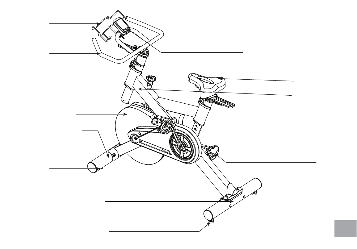
LEVELERS
HANDLE
BARS
WATER
BOTTLE
HOLDER
FLYWHEEL
FOOT PEDALS
LEVELERS
FRONT STABILIZER
REAR STABILIZER
MAIN FRAME
SEAT
CONSOLE
10
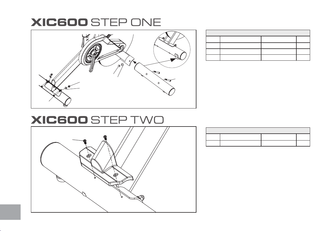
XIC600 STEP ONE
XIC600 STEP TWO
HARDWARE FOR STEP 1
PART TYPE DESCRIPTION QTY
81 CARRIAGE BOLTS
3/8”X3-1/2”
4
83 CURVED WASHERS
3/8”
4
82 CAP NUT
3/8”
4
HARDWARE FOR STEP 2
PART TYPE DESCRIPTION QTY
91 SCREWS
M5X10mm
2
1. Gather HARDWARE FOR STEP 1.
2. Install the FRONT AND REAR STABILIZERS
with four CARRIAGE BOLTS (81), four
CURVED WASHERS (83) and four CAP NUTS
(82). The front and rear stabilizer are different.
Be sure to assemble the stabilizer with the wheels
onto the front of the bike.
1. Gather HARDWARE FOR STEP 2.
2. Install the REAR STABILIZER COVER with two
SCREWS (91).
82
82
83
83
81
81
91
11
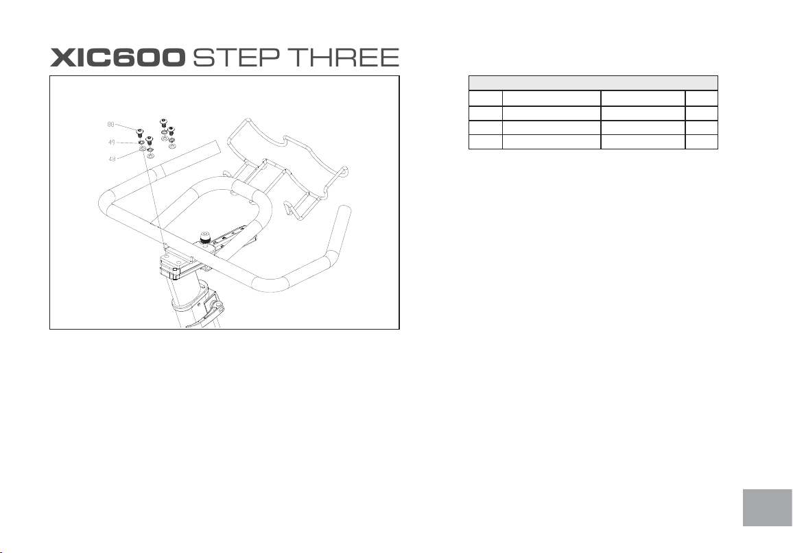
XIC600 STEP THREE
HARDWARE FOR STEP 3
PART TYPE DESCRIPTION QTY
88 BOLT
5/16”X15mm
4
49 SPLIT WASHERS
5/16”
4
48 FLAT WASHERS
5/16”
4
1. Gather HARDWARE FOR STEP 3.
2. Install the handlebars with four BOLTS (88),
SPLIT WASHERS (49) and four FLAT
WASHERS (48). Tighten the bolts securely.
3. Install the BOTTLE HOLDER to the handlebars
by loosening the thumb screw, clamp to the
handlebars and re-tightening the thumb screw.
8
STEP 3 Handlebar and Drink Holder
Install the handlebars with four 5/16" x 15mm bolts (88), 5/16" split washers (49) and four
5/16” flat washers (48). Tighten the bolts securely.
Install the drink holder to the handlebars by loosening the thumb screw, clamp to the
handlebars and re-tighten the thumb screw.
12
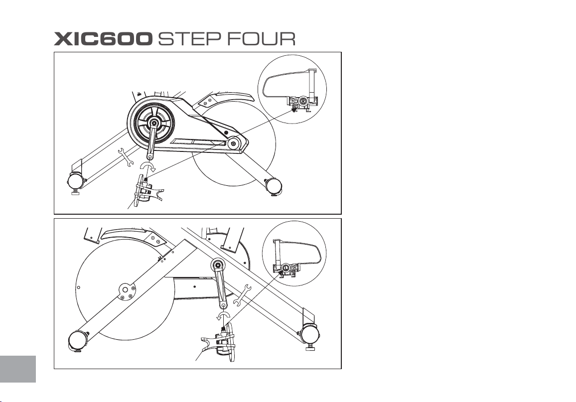
XIC600 STEP FOUR
1. Install the LEFT (25L) and Right (25R) pedals to
the crank arms.
Please note that the Left pedal has a reverse
threaded bolt and needs to be tightened in
a counterclockwise direction. The pedals are
identied by either an R or L stamped into the
end of the bolt.
25(R)
25(L)
13
XIC600 STEP FIVE
Cycling Console Battery Installation:
1. Remove the battery cover from the back of the computer.
2. Insert 2 AAA batteries into the battery compartment and reinstall
the battery cover.
3. When Battery working voltage is too low, The “Low battery”
indicator will show up on the console display indicating it is time to
change the batteries.
Speed Sensor Transmitter Battery Installation
1. Remove the battery cover from the transmitter.
2. Install 2 AAA batteries in the battery compartment and reinstall
the battery cover.
3. When new batteries are installed in the transmitter or console
you must perform the synchronizing procedure below for the
console to work properly
Synchronizing the transmitter to the console:
1. After installing the batteries, and before attaching the console and
transmitter to the bike, you must synchronize the two so they can
“talk” to each other.
2. Press and hold the two keys on the front of the console for about
3 seconds until the display shows ID - -
3. Now press and hold the blue button on the transmitter for 3
seconds and release. The console display should show ID 0. NOTE:
You must press the blue button within 10 seconds after the
console is showing ID - - otherwise the console will show: ID ER. If
the console shows this error then restart the procedure again.
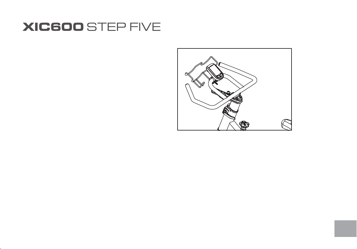
Installation of the cycling monitor
Console Installation:
1. Install the mounting clamp (2) to the back of the console (1) with
the clamp mounting screw (3).
2. Install and slightly tighten the thumb screw (4) then adjust the
console angle for optimal visibility. Once the console is adjusted,
continue to tighten the screw until it is securely attached to the
handle bar.
4. It may be necessary to remove and re-install the batteries in both
the console and transmitter if you continue to receive an error.
14
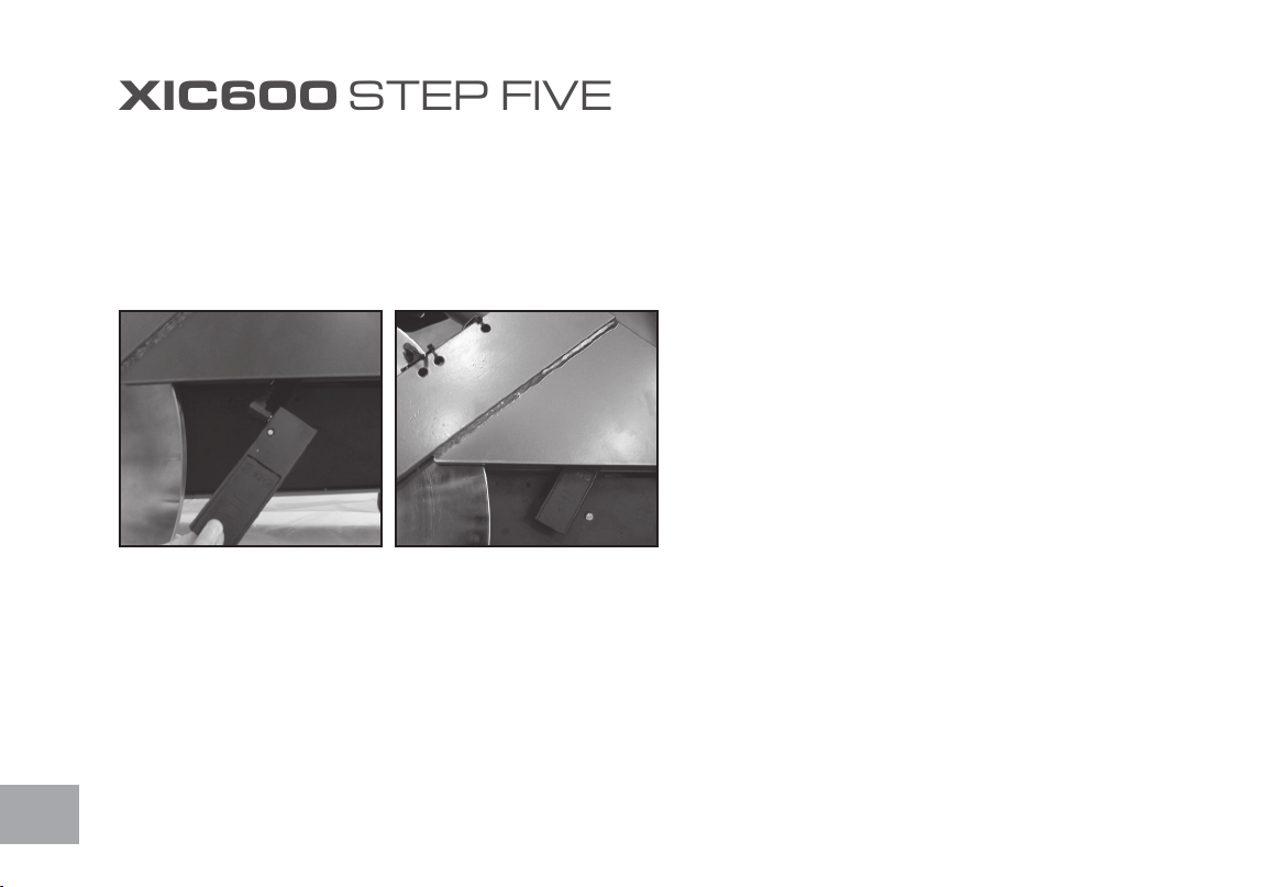
Installing the speed transmitter:
1. Plug the speed sensor wire into the transmitter (6) and then
attach the transmitter (with Velcro pre-attached to the back) to
the Velcro half that is pre-installed to the bike frame. The Velcro is
mounted to the back side of the chain cover, below the left crank.
XIC600 STEP FIVE
15
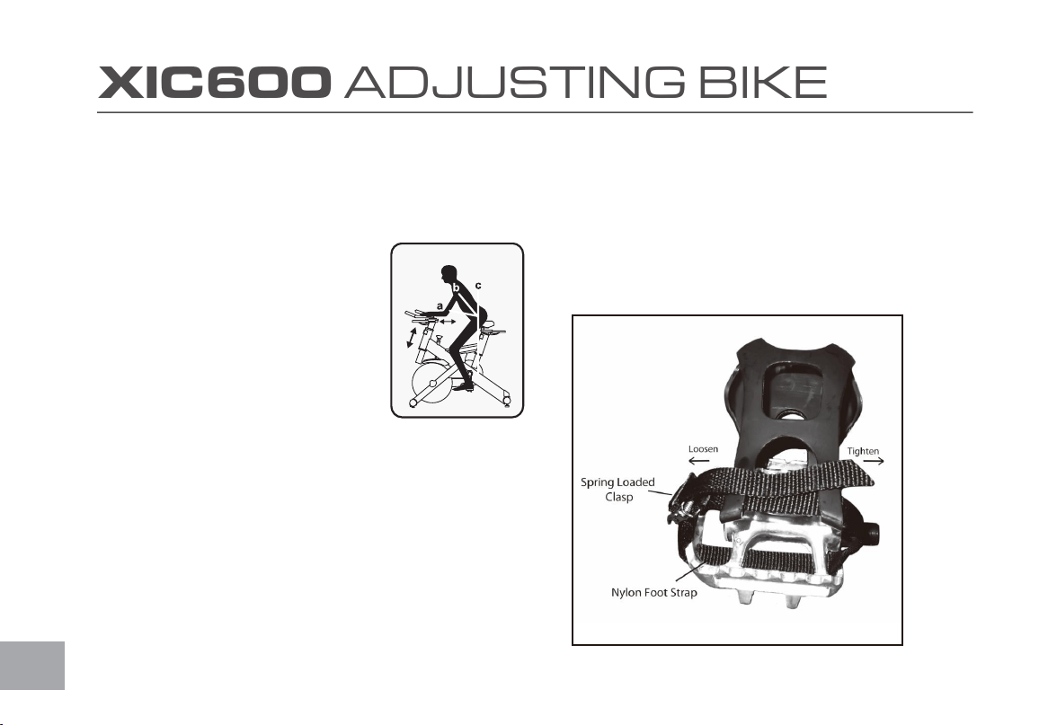
XIC600 ADJUSTING BIKE
Take some time to learn how to properly adjust the bike
to your body; it will make your workouts more pleasant
and a safer experience too. Riding the bike when it
is incorrectly adjusted can result in discomfort and
increase your risk of injury.
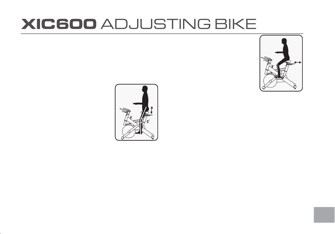
Adjustment of Seat Position
Seat Height Adjustment
1. Standing next to the bike, adjust seat until it
is about hip height.
2. Rotate crank arms until the pedals are in
the vertical position: 12 and 6 o’clock.
3. Place your foot in toe cage of pedal closest
to the oor and mount the bike. Ensure
that the ball of your foot is over the center
of pedal. Your leg should be slightly bent at
the knee, about 5 degrees.
4. If your leg is too straight or your foot cannot touch pedal you
will need to lower seat height. If your leg is bent too much
you will need to raise seat height.
5. Dismount the bike. Loosen the quick release lever on seat
post and adjust up or down as necessary.
6. When seat is in the desired position, tighten the quick release
to secure the seat post.
7. Note the nal position mark on the seat post for future
reference. Seat height can change when wearing different
shoes, always wear shoes when cycling.
Adjustment of Seat Position
Seat Forward /Aft Adjustment
1. Sit on bike with crank arms in the 3 and 9
o’clock positions. For road bike training, a
proper forward/aft position of the seat is
achieved when small bump at the top of
the shin is above pedal axle.
2. Dismount the bike. Loosen the quick
release under the seat and slide the seat
forward or backward as desired; then
tighten the quick release.
16
Handlebar Adjustment
Handlebar Height Adjustment
1. The Handlebar height is a matter of preference. Start with a
handlebar height that is the same as the seat’s height. Adjusting the
handlebar higher will give the rider a more upright position; lower
will result in a more crouched position.
2. Raise or lower the handlebar by loosening
quick release on handlebar post and adjust
by sliding the handlebar mount up or down
as desired. Then tighten the quick release to
secure the handlebar post. Note the nal
position mark on handlebar post for future
reference.
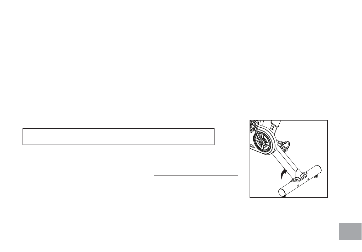
Adjusting the Pedal Straps
1. Place your feet in between the aluminum surface of the pedal and
the nylon foot strap that wraps around it. If the opening is too
narrow, depress the spring loaded clasp with one hand and pull on
the nylon strap with the other to increase the opening area. If it is
too loose or to tighten the strap, depress the spring loaded clasp,
then pull on the open end of the nylon strap until the strap is snug
around each foot.
Adjustment of Handlebar’s
Forward/Aft Position
1. Loosen the quick release under the handlebar and slide the
handlebar forward or backward as desired. Suitable forward/aft
position should allow the rider to comfortably grasp the handlebar
with a slight bend at the elbow.
2. Tighten the quick release to secure the handlebar assembly.
XIC600 ADJUSTING BIKE
11
DUAL FUNCTION PEDAL
ADJUSTING THE PEDAL STRAPS
Place your feet in between the aluminum surface of the pedal and the nylon foot strap that
wraps around it. If the opening is too narrow, depress the spring loaded clasp with one hand
and pull on the nylon strap with the other to increase the opening area. If it is too loose or to
tighten the strap, depress the spring loaded clasp, then pull on the open end of the nylon
strap until the strap is snug around each foot.

17
XIC600 BASIC OPERATION
Now that you have established a proper riding position, take a few minutes to ride the bike and determine that your position is comfortable. Start
pedaling at a slow pace with your toes and knees pointed directly forward. Hold the handlebar lightly and in a position that allows your shoulders
and upper body to relax. Pedal easily, at a low resistance until you feel condent that you could ride in that position for the duration of your
workout.
WARNING!
IF AT ANY TIME DURING YOUR WORKOUT, YOU FEEL CHEST PAIN, EXPERIENCE SEVERE MUSCULAR DISCOMFORT, FEEL FAINT,
OR ARE SHORT OF BREATH, STOP EXERCISING AT ONCE. IF THE CONDITION PERSISTS, YOU SHOULD CONSULT YOUR MEDICAL
DOCTOR IMMEDIATELY.
1. Pedaling resistance is controlled by the tension knob. Resistance can be changed at any time by turning tension knob: clock-wise for more
resistance; counterclockwise for less resistance.
2. To apply the brake, press down on the tension knob.
3. Before dismounting, apply the brake to stop ywheel, or increase resistance and let ywheel come to a stop.
4. Always follow the safety guidelines to minimize risk of injury.
18
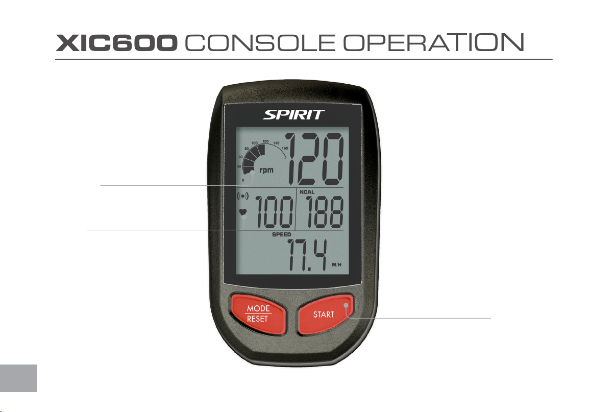
XIC600 CONSOLE OPERATION
Large LCD
Matrix Window
Easy-Touch
Control Buttons
Built-in Heart
Rate Receiver

19
XIC600 CONSOLE OPERATION
PLEASE NOTE:
1. The Cycling Monitor system is designed as sealed unit and not
meant to be opened other than for the sole purpose of installing
batteries. Any opened units will void the warranty.
2. To clean the Cycling Monitor use a clean damp cloth. Use of any
caustic cleaning solutions will void the warranty.
3. The Cycling Monitor system is NOT waterproof, only water
resistant. Any excessive exposure to water will void the warranty.
CONSOLE SPECIFICATION
CADENCE BAR GRAPH: 0~200rpm/10rpm per Bar
RPM : 0 ~ 240 RPM
SPEED : 0 ~ 96 KM/H (0 ~ 60 mph)
PULSE : 30 ~ 240 BPM
Time : Count down range 1~99 Minutes
Count up range 00:01~99:59
IMPORTANT SAFETY INSTRUCTIONS WARNING
BEFORE BEGINNING THIS OR ANY OTHER EXERCISE PROGRAM,
CONSULT A PHYSICIAN. THE PHYSICIAN CAN HELP YOU BETTER
DETERMINE WHAT ACTIVITIES OR PROGRAMS ARE MOST SUITED
FOR YOU. IF AT ANY TIME DURING THE WORKOUT YOU FEEL
FAINT, OR CHEST PAINS, OR SEVER SHORTNESS OF BREATH,
STOP EXERCISING IMMEDIATELY AND CONSULT A PHYSICIAN.
The Cycling Console carton consists of a computer console, speed
sensor transmitter. The transmitter counts the number of times the
magnet, which is mounted on the crank assembly, passes the sensor. The
speed sensor transmitter will then send a coded signal to the console
which contains the measured value (Speed and Cadence ).
Both the computer console and the speed sensor transmitter use AAA
type batteries. Please install the supplied AAA batteries in the computer
console and speed sensor transmitter before using.
20
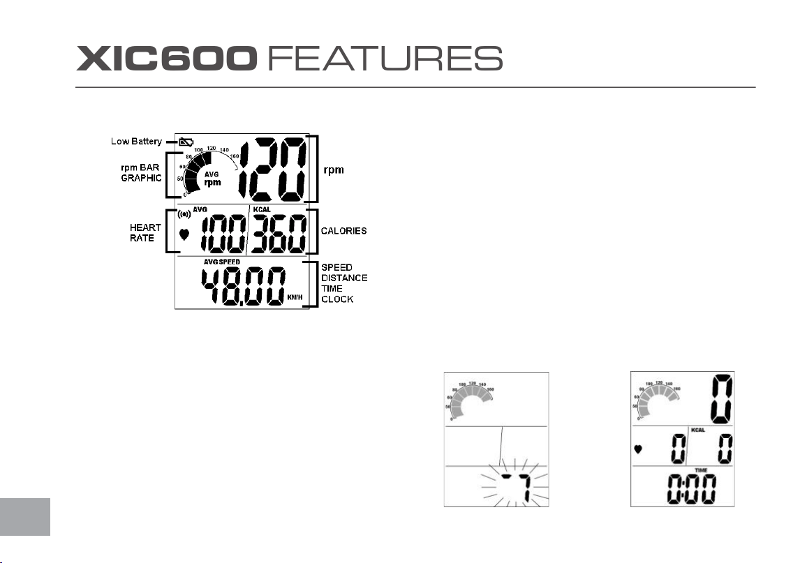
XIC600 F E AT U R ES
TIME
Time is measured in min:sec
There is a time of day clock and a workout timer clock. The workout
time will count up or count down during pedaling. If pedaling stops, the
time will stop counting after 3sec.
RPM/CADENCE
Cadence is the measurement of how fast the cranks are rotating in
RPM. The approximate speed of the bike can also be display in MPH
or KPH. In addition to the MPH/KPH, the RPM section of the display
also has a bar graph that allows the rider to visually keep track of the
approximate RPM.
5
6
4
3
2
1
1 – Console
2 – Mounting Clamp
3 – Clamp mounting screw
4 – Clamping thumb screw
5 – Velcro
6 – Speed transmitter
7
DISPLAY WINDOW
TIME
Time is measured in min:sec
There is a time of day clock and a workout timer clock.
The workout time will count up or count down during
pedaling. If pedaling stops, the time will stop counting
after 3sec.
RPM/CADENCE
Cadence is the measurement of how fast the cranks are
rotating in RPM. The approximate speed of the bike can
also be display in MPH or KPH.
In addition to the MPH/KPH, the RPM section of the
display also has a bar graph that allows the rider to
visually keep track of the approximate RPM.
8
DISTANCE
Distance is the measurement of the virtual distance traveled on the
bike. This distance is based on the user riding a bike with tires that are
the same size as the group bike’s ywheel.
KCAL
Kcal is the approximation of calories burned during your work out. The
calories are an estimate only.
HEART RATE
This the approximation of heart rate detected from the chest belt
during your work out. (Heart-Rate Strap sold separately.)
QUICK Start
When the console is in Power Saving Mode, hold down any key to
wake up the console and go to the start-up screen, also called “QUICK
START” active state.
DISTANCE
Distance is the measurement of the virtual distance
traveled on the bike. This distance is based on the user
riding a bike with tires that are the same size as the
group bike‟s flywheel.
KCAL
Kcal is the approximation of calories burned during your
work out. The calories are an estimate only.
HEART RATE
This the approximation of heart rate detected from the
chest belt during your work out.
QUICK Start
When the console is in Power Saving Mode, hold down
any key to wake up the console and go to the start-up
screen, also called “QUICK Start” active state.
Power Saving Mode QUICK START Mode
9
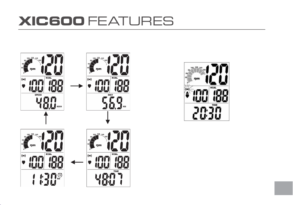
MODE SELECT
Press the left hand key to select the SPEED, DIST, TIME
or CLOCK at the bottom of the display.
10
21
XIC600 F E AT U R ES
MODE SELECT
Press the left hand key to select the SPEED, DIST, TIME, or CLOCK
at the bottom of the display.
DISTANCE
Distance is the measurement of the virtual distance
traveled on the bike. This distance is based on the user
riding a bike with tires that are the same size as the
group bike‟s flywheel.
KCAL
Kcal is the approximation of calories burned during your
work out. The calories are an estimate only.
HEART RATE
This the approximation of heart rate detected from the
chest belt during your work out.
QUICK Start
When the console is in Power Saving Mode, hold down
any key to wake up the console and go to the start-up
screen, also called “QUICK Start” active state.
Power Saving Mode QUICK START Mode
9
MODE SELECT
Press the left hand key to select the SPEED, DIST, TIME
or CLOCK at the bottom of the display.
10
RESET/HEART RATE ALARM SELECT
Press the right hand key to activate the heart rate alarm. If the alarm is
on, the alarm icon will ash and a beep will sound to indicate that your
heart rate is either above or below the selected target zone.
RESET: Press and hold the right hand key for 3 seconds. All the
accumulated values for AVG SPEED, AVG PULSE, TIME, DIST, KCAL will
return to zero.
TIME OF DAY
1. If you want to change the time of day settings at any time press
the left hand key until time of day is displayed then press the
right hand key for 3 seconds. The display will ash an indication of
whether the clock is set for 12H clock or 24H military time clock.
Press the right hand key to change.
RESET/HEART RATE ALARM SELECT
1. Press the right hand key to activate the heart rate
alarm. If the alarm is on, the alarm icon will flash and a
beep will sound to indicate that your heart rate is either
above or below the selected target zone.
2. RESET: Press and hold the right hand key for 3
seconds. All the accumulated values for AVG SPEED,
AVG PULSE, TIME, DIST, KCAL will return to zero.
TIME OF DAY
1. If you want to change the time of day settings at any
time press the left hand key until time of day is displayed
then press the right hand key for 3 seconds. The display
will flash an indication of whether the clock is set for 12H
clock or 24H military time clock. Press the right hand key
to change.
11
2. Press the left hand key to switch to the hour setting,
use the right hand key to change hours.
3. Press the left hand key again to switch to minutes and
use the right hand key to change the minutes.
4. When you are finished, wait a few seconds for the
display to return to the start-up screen.
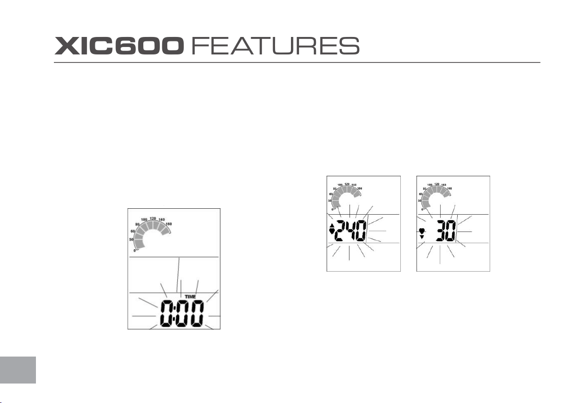
Setting Workout Time
1. Press and hold the right hand key when the bottom
section of the display is showing SPEED; the Minutes
will now be flashing. Press the right hand key to
increase Minutes setting.
2. To clear the exercise Time press the left hand key until
the time is displayed then hold the right hand key for
three seconds.
12
22
XIC600 F E AT U R ES
2. Press the left hand key to switch to the hour setting, use the right
hand key to change hours.
3. Press the left hand key again to switch to minutes and use the
right hand key to change the minutes.
4. When you are nished, wait a few seconds for the display to
return to the start-up screen.
Setting Workout Time
Press and hold the right hand key when the bottom section of the
display is showing SPEED; the Minutes will now be ashing. Press the
right hand key to increase Minutes setting.
2. To clear the exercise Time press the left hand key until the time is
displayed then hold the right hand key for three seconds.
RESET/HEART RATE ALARM SELECT
1. Press the right hand key to activate the heart rate
alarm. If the alarm is on, the alarm icon will flash and a
beep will sound to indicate that your heart rate is either
above or below the selected target zone.
2. RESET: Press and hold the right hand key for 3
seconds. All the accumulated values for AVG SPEED,
AVG PULSE, TIME, DIST, KCAL will return to zero.
TIME OF DAY
1. If you want to change the time of day settings at any
time press the left hand key until time of day is displayed
then press the right hand key for 3 seconds. The display
will flash an indication of whether the clock is set for 12H
clock or 24H military time clock. Press the right hand key
to change.
11
2. Press the left hand key to switch to the hour setting,
use the right hand key to change hours.
3. Press the left hand key again to switch to minutes and
use the right hand key to change the minutes.
4. When you are finished, wait a few seconds for the
display to return to the start-up screen.
Setting Workout Time
1. Press and hold the right hand key when the bottom
section of the display is showing SPEED; the Minutes
will now be flashing. Press the right hand key to
increase Minutes setting.
2. To clear the exercise Time press the left hand key until
the time is displayed then hold the right hand key for
three seconds.
12
HEART RATE TARGET ZONES
Press the left hand key until “SPEED” is displayed then hold the right
hand key for 3 seconds. The TIME will be ashing; press the left hand key
to select the heart rate target zone settings.
Press the right hand key to increase maximum heart rate limit. After
setting the maximum heart rate, press the left hand key to adjust the
minimum heart rate limit.
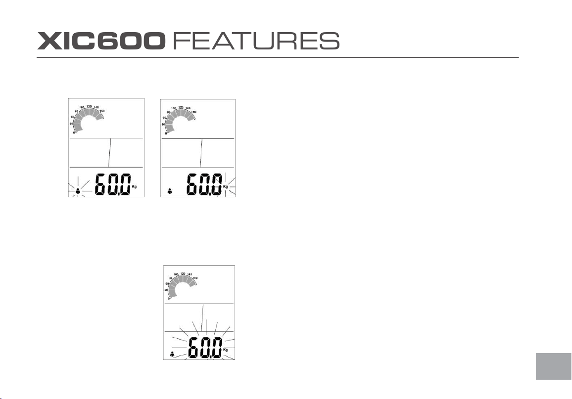
PERSONAL DATA SETTING
1. GENDER: Press the left hand key until SPEED is displayed then,
press the right hand key for 3 seconds. The TIME will be ashing,
press the left hand key until the gender icon is blinking. Press the
right hand key to select the gender
HEART RATE TARGET ZONES
Press the left hand key until „SPEED‟ is displayed then
hold the right hand key for 3 seconds. The TIME will be
flashing; press the left hand key to select the heart rate
target zone settings.
Press the right hand key to increase maximum heart rate
limit. After setting the maximum heart rate, press the left
hand key to adjust the minimum heart rate limit.
PERSONAL DATA SETTING
1. GENDER: Press the left hand key until SPEED is
displayed then, press the right hand key for 3 seconds.
The TIME will be flashing, press the left hand key until
the gender icon is blinking. Press the right hand key to
select the gender.
13
2. Press the left hand key to set the measuring value for
weight (Lb or Kg), press the right hand key to select.
3. BODYWEIGHT: Press the left hand key to set the
bodyweight, press the right hand key to increase the
weight. Press and hold the right hand key for rapid
advance.
14
23
XIC600 F E AT U R ES
2. Press the left hand key to set the measuring value for weight (Lb
or Kg), press the right hand key to select.
3. BODYWEIGHT: Press the left hand key to set the bodyweight,
press the right hand key to increase the weight. Press and hold the
right hand key for rapid advance.
HEART RATE TARGET ZONES
Press the left hand key until „SPEED‟ is displayed then
hold the right hand key for 3 seconds. The TIME will be
flashing; press the left hand key to select the heart rate
target zone settings.
Press the right hand key to increase maximum heart rate
limit. After setting the maximum heart rate, press the left
hand key to adjust the minimum heart rate limit.
PERSONAL DATA SETTING
1. GENDER: Press the left hand key until SPEED is
displayed then, press the right hand key for 3 seconds.
The TIME will be flashing, press the left hand key until
the gender icon is blinking. Press the right hand key to
select the gender.
13
2. Press the left hand key to set the measuring value for
weight (Lb or Kg), press the right hand key to select.
3. BODYWEIGHT: Press the left hand key to set the
bodyweight, press the right hand key to increase the
weight. Press and hold the right hand key for rapid
advance.
14

24
TROUBLESHOOTING
No Display on Console
Hold down any key to bring the console to “Quick Start” mode.
Ensure that the batteries are installed properly in the console and transmitter. If they are, install fresh batteries.
No Heart Rate signal displayed
Ensure that your chest strap (sold separately) is worn correctly and that there is moisture under the electrodes.
Relocate the bike away from any equipment that could potentially interrupt the radio frequency signal, such as a DVD player
or television, etc.
Cadence number jumps high or low
Separate bikes that may be set to the same console code and are cross-talking, or re-synchronize the transmitter and
console (see page 5). Relocate the bike to a different part of the room, away from any RF interference areas.
Heart Rate signal gets interrupted or drops out
Ensure that there is a minimum distance of 36 inches between bikes. Verify that your chest strap (sold separately) is secure
and that the electrodes are making contact with your chest at all times.
CAUTION
EXTERNAL INTERFERENCE MAY BE CAUSED BY OTHER ELECTRONIC DEVICES, SUCH AS: NEARBY TELEVISIONS, STEREO EQUIPMENT,
SPEAKERS, ELECTRICAL WIRE CABLING, ETC. IF YOU EXPERIENCE DISTURBANCES IN THE CONSOLE DISPLAY TRY MOVING YOUR BIKE(S)
AWAY FROM POTENTIAL RF INTERFERENCE AREAS.
Notice of FCC Compliance
This equipment has been tested and found to comply with the limits for a Class C Low Power Communication Device Transmitter,
pursuant to Part 15 of the FCC rules. Operation is subject to the following conditions: (1) This device may not cause harmful
interference, and (2) this device must accept any interference received, including interference that may cause undesired operation.
There is no guarantee that interference will not occur in a particular installation. If this equipment experiences interference from a
radio, television, or other RF signal, the user is encouraged to try and correct the interference by increasing the separation between
the equipment and the apparatus emitting the interfering RF signal.

25
GENERAL MAINTENANCE
1. Do not service internal parts of pedals. If they are found to be worn internally, we recommend replacing the pedal.
2. Use of lubricants or cleaning solutions other than those specied will result in diminished performance and a shorter
life span for that part.
3. Wipe down all areas in the sweat path with a damp cloth after each workout.
4. If a squeak, thump, clicking or rough feeling develops the main cause is most likely one of three reasons:
I. The hardware was not sufciently tightened during assembly. All bolts that were installed during assembly need to
be tightened as much as possible. It may be necessary to use a larger wrench than the one provided if you cannot
tighten the bolts sufciently. We cannot stress this point enough; 90% of calls to the service department for noise
issues can be traced to loose hardware.
II. The crank arm nut needs to be retightened.
III. If squeaks or other noises persist, check that the unit is properly leveled. There are 2 leveling pads on the bottom
of the rear stabilizer, use a 14mm wrench (or adjustable wrench) to adjust the levelers.
Part Recommended Action Frequency Cleaner Lubricant
Pedals
Ensure that pedals are tight in crank arms; that all
screws on pedals are tight; and that the pedal straps
are not frayed
Before each
Use
N/A N/A
Frame Wipe down by using a soft damp clean cloth Daily Water N/A
Flywheel
Wipe down by spraying on a rag and applying a light
coat to sides of the ywheel
Weekly
WD-40
Spray
N/A
Brake Pad Inspect for excessive wear or a dry leather brake pad Weekly N/A
3-IN-ONE Oil or
10W Oil.
Do not use
Silicone-based
Lubricants

26
Indoor Cycle Warranty - Effective August 22, 2018
Spirit Fitness, Inc. (Spirit Fitness) warrants all its Indoor Cycle parts for a period of time listed below from the date of retail sale, as determined by sale
receipt, or in the absence of a sales receipt eighteen (18) months from the original factory shipping date. Spirit Fitness’ responsibilities include providing
new or remanufactured parts, at Spirit Fitness’ option, and technical support to our independent dealers and servicing organizations. In the absence of a
dealer or service organization, these warranties will be administered by Spirit Fitness directly to a consumer. The warranty period applies to the following
components:
NORMAL RESPONSIBILITIES OF THE CONSUMER
This warranty applies only to products in ordinary household (see restrictions above), and the consumer/facility is responsible for the items listed below:
1. The warranty registration card must be completed and returned to the address listed on the card within 10 days of the original purchase to validate
the manufacturer’s limited warranty.
2. Proper use of the Indoor Bike in accordance with the instructions provided in this manual
3. Proper installation in accordance with instructions provided with the Indoor Bike and with all local electric codes.
4. Expenses for making the Indoor Bike accessible for servicing, including any item that was not part of the Indoor Bike at the time it was shipped from
the factory.
5. Damages to the Indoor Bike nish during shipping, installation or following installation.
6. Routine maintenance of this unit as specied in this manual.
EXCLUSIONS
This warranty does not cover the following:
1. CONSEQUENTIAL, COLLATERAL, OR INCIDENTAL DAMAGES SUCH AS PROPERTY DAMAGE AND INCIDENTAL EXPENSES
RESULTING FROM ANY BREACH OF THIS WRITTEN OR ANY IMPLIED WARRANTY.
Note: Some states do not allow the exclusion or limitation of incidental or consequential damages, so this limitation or exclusion may not apply to
you.
2. Service call reimbursement to the consumer. Service call reimbursement to the dealer that does not involve malfunction or defects in workman-
ship or material, for units that are beyond the warranty period, for units that are beyond the service call reimbursement period, for Indoor Bike not
requiring component replacement, or Indoor Bike not in ordinary household or light commercial use.
3. Damages caused by services performed by persons other than authorized Spirit Fitness service companies; use of parts other than original Spirit
Fitness parts; or external causes such as corrosion, discoloration of paint or plastic, alterations, modications, abuse, misuse, accident, improper mainte-
nance, inadequate power supply, or acts of God.
4. Products with original serial numbers that have been removed or altered.
5. Products that have been: sold, transferred, bartered, or given to a third party.
Warranty
Residential
Frame
Lifetime
Parts
3 Years
Labor
1 Year

27
6. Products that do not have a warranty registration card on le at Spirit Fitness. Spirit Fitness reserves the right to request proof of
purchase if no warranty record exists for the product.
7. THIS WARRANTY IS EXPRESSLY IN LIEU OF ALL OTHER WARRANTIES EXPRESSED OR IMPLIED, INCLUDING THE WARRANTIES OF
MERCHANTABILITY AND/OR FITNESS FOR A PARTICULAR PURPOSE.
8. Product use in any environment other than a residential setting or non-dues paying facility with 5 hours use or less per day.
9. Warranties outside of the United States may vary. Please contact your local dealer for details.
SERVICE
Keep your bill of sale. Twelve (12) months from the date on the bill of sale or eighteen (18) months from the date of factory shipping as
determined by the serial number establishes the labor warranty period should service be required. If service is performed, it is in your best
interest to obtain and keep all receipts. This written warranty gives you specic legal rights. You may also have other rights that vary from
state to state. Service under this warranty must be obtained by following these steps, in order:
1. Contact your selling authorized Spirit Fitness dealer. OR
2. Contact your local authorized Spirit Fitness service organization.
3. If there is a question as to where to obtain service, contact our service department at (870) 935-1107.
4. Spirit Fitness’ obligation under this warranty is limited to repairing or replacing, at Spirit Fitness’ option, the product through one of our authorized
service centers. All repairs must be preauthorized by Spirit Fitness. If the product is shipped to a service center freight charges to and from the
service
center will be the customer’s responsibility. For replacement parts shipped while the product is under warranty, the customer will be
responsible for shipping and handling charges. For in-home service, the customer will be responsible for a trip charge. There will be an
additional trip charge if the customer is located over 100 miles from the nearest service center.
5. The owner is responsible for adequate packaging upon return to Spirit Fitness. Spirit Fitness is not responsible for damages in shipping. Make all freight
damage claims with the appropriate freight carrier. DO NOT SHIP ANY UNIT TO OUR FACTORY WITHOUT A RETURN AUTHORIZATION
NUMBER. All units arriving without a return authorization number will be refused.
6. For any further information, or to contact our service department by mail, send your correspondence to:
Spirit Fitness, Inc.
P.O. Box 2037
Jonesboro, AR 72402-2037
Product features or specications as described or illustrated are subject to change without notice. All warranties are made by Spirit Fitness, Inc. This
warranty applies only in the 48 contiguous United States. NOTE: This does not apply to Alaska or Hawaii.

28

800.258-8511
spiritservice@spirittness.com
www.spirittness.com
Spirit Fitness
3000 Nestle Road
Jonesboro, AR 72401
XIC600 Owners Manual
© 2018 All Rights Reserved
Revision: 08.22.2018