Cybex 771A/771AT, 772A/772AT Arc Trainer
®
Owner's Manual
Part Number 5771-4 K
www.cybexintl.com

Table of Contents
Safety
Safety Guidelines and Practices.........................4
Power Cord Information......................................4
Important Safety Instructions..............................5
Warnings and Cautions......................................6
Label Placement.................................................8
Assembly
Specifications - 771A/772A..............................10
Specifications - 771AT/772AT...........................11
Choosing and Preparing Site............................12
Environment.....................................................13
Electrical Power Requirements........................13
Assembly Procedure 771A/772A......................14
Assembly Procedure 771AT/772AT..................27
Setup................................................................43
Testing Operation.............................................45
Operation
Intended Use....................................................47
Individual human power versus mechanical
power...........................................................47
Terms Used......................................................47
Console Display................................................48
User Control Symbols Used.............................49
CardioTouch Symbols Used.............................50
CardioTouch Screen and User Controls...........52
Muscle Map and Incline Meter..........................53
Mount and Dismount........................................54
Range of Motion...............................................54
Quick Operation Guide.....................................55
Detailed Operation Guide.................................56
Workout Selection............................................57
Data Readouts - LED display...........................58
E3 View Monitor Screen Options......................59
Heart Rate Indicator.........................................59
Fan Control.......................................................60
How power input versus displayed value is
calculated.....................................................60
Testing Parameters...........................................60
Maintenance
Warnings...........................................................62
Clean Unit.........................................................62
Drive Belts........................................................64
Rechargeable Battery.......................................65
E3 View Monitor................................................65
Service Schedule..............................................66
Statistics...........................................................67
Customer Service
Product Registration.........................................69
Contacting Service...........................................69
Ordering Parts..................................................69
Return Material Authorization (RMA)................70
Damaged Parts.................................................70
Appendix - Workout Overviews
Weight Loss - Hill Climb...................................71
Weight Loss - Speed Bump..............................73
Strength - High Low..........................................75
Strength - Bursts...............................................77
Strength - Interval.............................................79
Fitness (Mens) , Shaping (Womens) - Total
Leg...............................................................81
Fitness (Mens) - Target: Hip, Shaping
(Womens) - Glute Camp..............................83
Cardio - Wave...................................................85
Cardio - Interval................................................87
Cardio - Hill Interval..........................................89
Cardio - Heart Rate Control..............................91
Power - Constant Power...................................93
Power - Adaptive Power...................................94
Cybex
®
and the Cybex logo are registered trademarks of Cybex International, Inc. Polar
®
is a registered trademark of Polar Electro Inc.
DISCLAIMER: Cybex International, Inc. makes no representations or warranties regarding the contents of this manual. We reserve the right to
revise this document at any time or to make changes to the product described within it without notice or obligation to notify any person of such
revisions or changes.
©
Copyright 2016, Cybex International, Inc.
10 Trotter Drive, Medway, MA 02053 • 888-462-9239 • 508-533-4300 • FAX 508-533-5183
www.cybexintl.com • 5771-4 K • September 2016
Page 2 of 95
Cybex 771A/771AT, 772A/772AT Arc Trainer Part Number 5771-4 K

FCC Compliance Information
Changes or modifications to this unit not expressly approved by the party responsible for compliance
could void the user’s authority to operate the equipment.
This equipment has been tested and found to comply with the limits for a Class A digital device, pursuant
to part 15 of the FCC Rules. These limits are designed to provide reasonable protection against harmful
interference when the equipment is operated in a commercial environment. This equipment generates,
uses, and can radiate radio frequency energy and, if not installed and used in accordance with the
instruction manual, may cause harmful interference to radio communications. Operation of this equipment
in a residential area is likely to cause harmful interference in which case the user will be required to
correct the interference at his own expense.
Modifications not expressly approved by the manufacturer could void the user’s authority to operate the
equipment under FCC rules.
Page 3 of 95
Cybex 771A/771AT, 772A/772AT Arc Trainer Part Number 5771-4 K
Safety
Safety Guidelines and Practices
Read the Owner’s Manual carefully before assembling, servicing, or using the equipment. Owner
must comply with all safety guidelines in this manual. It is also the owner’s responsibility to instruct
users on the safe and proper operation of the equipment and to properly display any and all
warning labels and instructional placards. All users should read these labels and placards before
using equipment.
Serious injury or death could occur if the following safety precautions and
instructions are not followed.
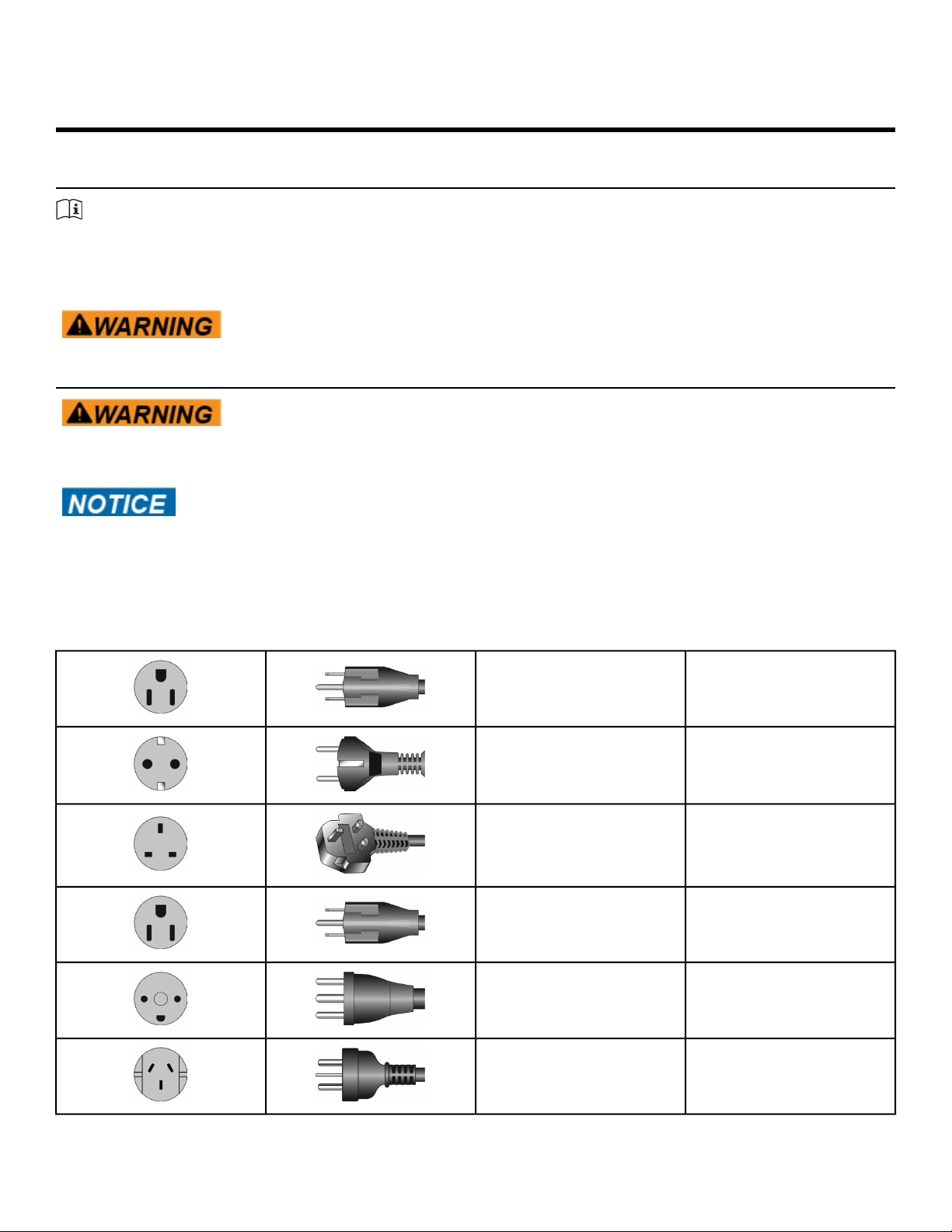
Power Cord Information
Shock and electrocution hazard.
• Connect unit to a grounded outlet.
• Do not use voltage adapter or extension cord.
Cybex is not responsible for injuries or damages as a result of cord or plug
modification.
• Verify voltage requirements of unit match local voltage requirements.
• Verify unit outlet is the same configuration as the plug.
Power cord configuration
NEMA 5-15115 VAC
CEE 7/7Euro Plug
BS 1363UK 230 VAC
JIS 8303Japanese
107-2-D1Danish
AS/NZS 3112Australia
Page 4 of 95
Cybex 771A/771AT, 772A/772AT Arc Trainer Part Number 5771-4 K
GB 2099-1 and GB
1002-1
Chinese
IEC-60320-C13Brazil
Important Safety Instructions
(Save These Instructions)
Shock and electrocution hazard.
• Unplug unit and let sit 10 minutes before cleaning or performing
maintenance.
• Electrical charge can remain in unit after unplugging.
• Keep water and liquids away from electrical parts.
User Safety Precautions
Prior to use:
• Obtain a medical exam before beginning any exercise program.
• Obtain instruction before using.
•
Read and understand warning labels.
• Keep foot plate surface clean and dry.
• Maximum user weight is 400 lbs. (180 kg).
• Inspect unit. If damaged, notify floor staff. DO NOT USE.
• Do not remove this label. Replace if damaged or illegible.
During use
• Do not use for stretching and do not attach straps or other devices.
• Do not allow children 12 or younger to be on or near machine.
• Stop exercise if feeling faint, dizzy, or have pain.
• Use the handrails for support and to maintain balance.
• Keep all body parts, clothing, and accessories, clear of moving parts.
• Wait until foot plates come to a complete stop before getting off.
Facility Safety Precautions
It is the sole responsibility of the user/owner or facility operator to ensure that regular maintenance is
performed.
• Enforce all user and safety precautions.
• Read and understand the Owner’s Manual completely before assembling, servicing or using unit.
• Verify all users are properly trained on using the equipment.
• Do not use unit outdoors.
Page 5 of 95
Cybex 771A/771AT, 772A/772AT Arc Trainer Part Number 5771-4 K

• Verify that each unit is setup, leveled and operated on a solid level surface. Do not install equipment
on an uneven surface.
• Verify there is enough room for safe access and operation of unit.
• Use Cybex AC power adapters only.
• Do not use the optional power adapter in damp or wet locations.
• Do not use the unit if: (1) the unit is plugged into an optional power adapter that has a damaged cord;
(2) the unit is not working properly or (3) if the unit has been dropped or damaged. Seek service from
a qualified technician.
• EQUIPMENT is not suitable for use in the presence of aerosol (spray), FLAMMABLE ANAESTHETIC
MIXTURE WITH AIR or WITH OXYGEN or NITROUS OXIDE.
• Perform regular maintenance checks on unit. Performance level can be maintained only if examined
regularly. Pay close attention to all areas most susceptible to wear, including (but not limited to)
cables, pulleys, belts and grips.
• Replace any warning labels if damaged, worn, or illegible.
• Immediately replace worn or damaged components. If unable to immediately replace worn or damaged
components, then remove unit from service until repair is made.
• Do not attempt electrical or mechanical repairs.
Seek qualified repair personnel when servicing. If you live in the USA, contact Cybex Customer
Service at 888-462-9239. If you live outside the USA, contact Cybex Customer Service at
508-533-4300.
• Use only Cybex supplied components to maintain/repair unit.
• Keep a repair log of all maintenance activities.
• Disconnect the optional power adapter before servicing unit.
• Do not use attachments unless recommended for the unit by Cybex.
• The unit may generate electromagnetic or other forms of interference, or it may be affected by
interference from other equipment nearby. If this is suspected, take precautions by separating the
equipment or otherwise shielding it to avoid such interference.
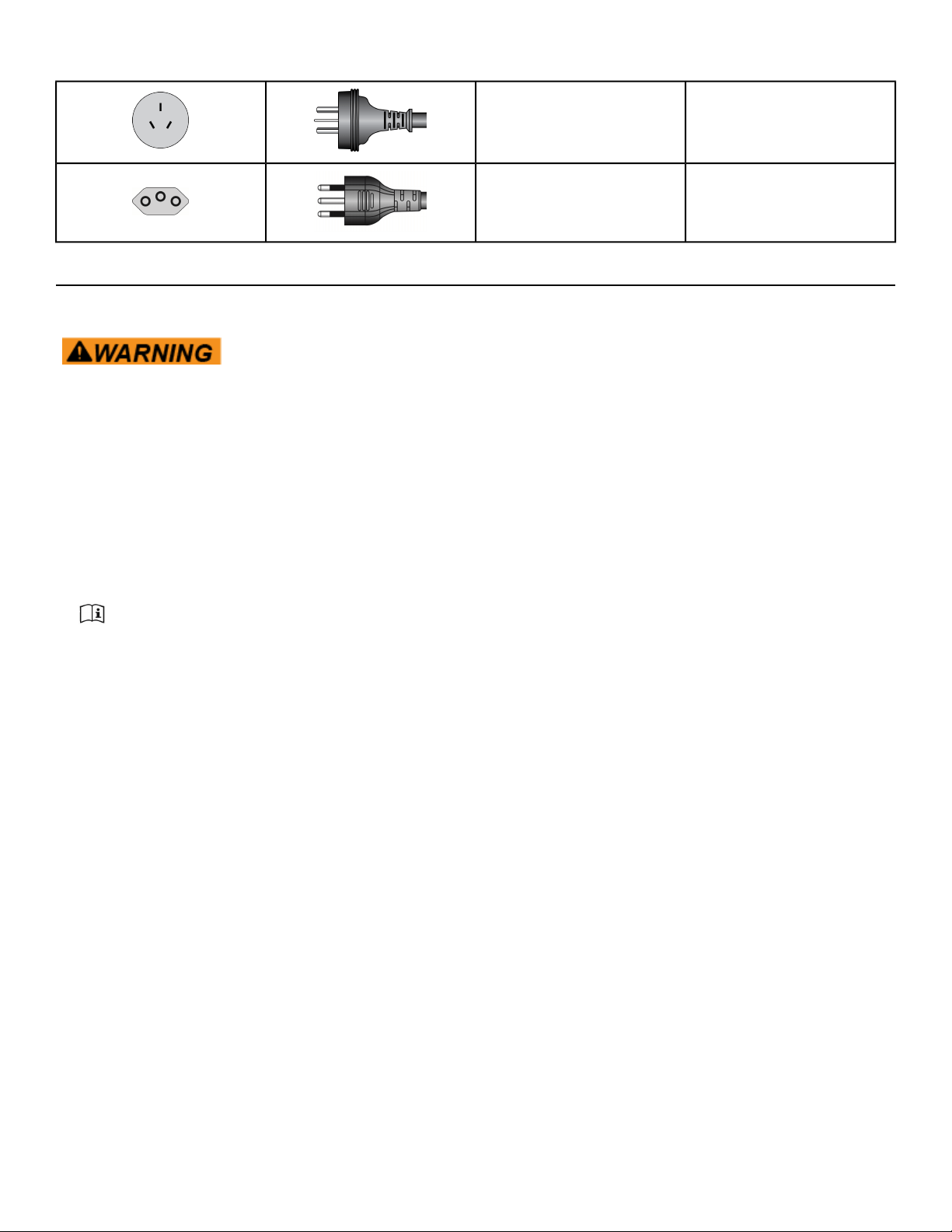
Warnings and Cautions
Warning labels indicate a potentially hazardous situation that could result in serious injury or death if
the precautions are not observed.
Caution labels indicate a potentially hazardous situation that could result in serious injury or damage to
machine if the precautions are not observed.
Contact Cybex Customer Service to replace any worn or damaged labels.
Page 6 of 95
Cybex 771A/771AT, 772A/772AT Arc Trainer Part Number 5771-4 K
Canadian
Page 7 of 95
Cybex 771A/771AT, 772A/772AT Arc Trainer Part Number 5771-4 K
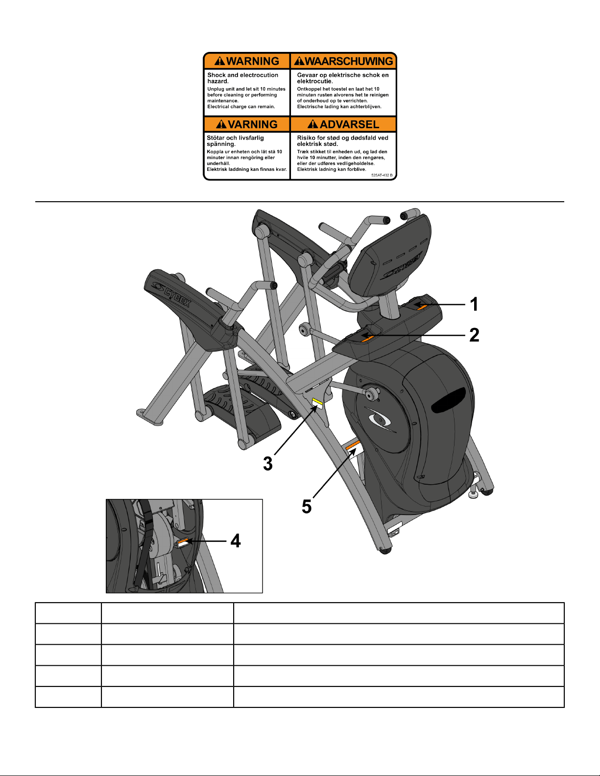
Label Placement
Label, Warning, Access tray, Left770A-331-X1
Label, Warning, Access tray, Left, Canadian770A-331-E1
Label, Warning, Access tray, Right770A-332-X2
Label, Warning, Access tray, Right, Canadian770A-332-E2
Decal, Caution moving partsDE000004-X3
Page 8 of 95
Cybex 771A/771AT, 772A/772AT Arc Trainer Part Number 5771-4 K

Label, Warning, Hot flywheelDE-17155-X4
Label, Warning, Disconnect Power525AT-4005
Label, Warning, Disconnect Power525AT-4015
Label, Warning, Disconnect Power525AT-4025
Label, Warning, Disconnect Power525AT-4185
Page 9 of 95
Cybex 771A/771AT, 772A/772AT Arc Trainer Part Number 5771-4 K

Assembly
Specifications - 771A/772A
S (Studio)Classification
AAccuracy
76.25” (194 cm)Assembled Length
32” (81 cm)Assembled Width
62.5”(159 cm)Assembled Height
404 lbs (183 kg)Weight of Product
429 lbs (195 kg)Shipping Weight
0-20 % gradeIncline Levels
0-100Resistance Levels
24” (61 cm) fixed lengthStride Length
Quick Start, five workout groups, seven workouts, four heart rate workouts,
and two power workouts
Workouts
Upper console: LED or E3 View Monitor. Displays Cal/Hr, Distance,
Strides per Minute, Calories, Watts, METs and BPM. Lower console: Two
numeric displays for incline, time, resistance and level. Fan, CardioTouch
screen, accessory trays and water bottle holder.
Console Features
Built-in 5 KHz wireless heart rate receiver (transmitter not included) and
contact heart rate monitoring.
Heart Rate Features
0 to 900 watts.Resistance Range
400 lbs. (180 kg).Maximum User Weight
Self powered or 100 - 240 VAC~, 50/60 Hz, 1.8A, 1-phase.Power Rating
AC Power Adapter, Set Top Box wiring (to support CAB and MYE using
Coax or HDMI).
Options
Page 10 of 95
Cybex 771A/771AT, 772A/772AT Arc Trainer Part Number 5771-4 K
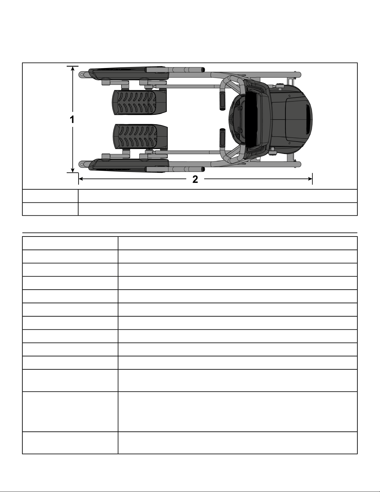
Top View 771A/772A
Dimensions
32” (81 cm)
1
62.5” (159 cm)2
Specifications - 771AT/772AT
S (Studio)Classification
AAccuracy
76.25” (194 cm)Assembled Length
36.28” (92 cm)Assembled Width
62.5”(159 cm)Assembled Height
412 lbs. (187 kg.)Weight of Product
437 lbs. (198 kg.)Shipping Weight
0-20 % gradeIncline Levels
0-100Resistance Levels
24” (61 cm) fixed lengthStride Length
Quick Start, five workout groups, seven workouts, four heart rate workouts,
and two power workouts
Workouts
Upper console: LED or E3 View Monitor. Displays Cal/Hr, Distance,
Strides per Minute, Calories, Watts, METs and BPM. Lower console: Two
numeric displays for incline, time, resistance and level. Fan, CardioTouch
screen, accessory trays and water bottle holder.
Console Features
Built-in 5 KHz wireless heart rate receiver (transmitter not included) and
contact heart rate monitoring.
Heart Rate Features
Page 11 of 95
Cybex 771A/771AT, 772A/772AT Arc Trainer Part Number 5771-4 K
0 to 900 watts.Resistance Range
400 lbs. (180 kg).Maximum User Weight
Self powered or 100 - 240 VAC~, 50/60 Hz, 1.8A, 1-phase.Power Rating
AC Power Adapter, Set Top Box wiring (to support CAB and MYE using
Coax or HDMI).
Options
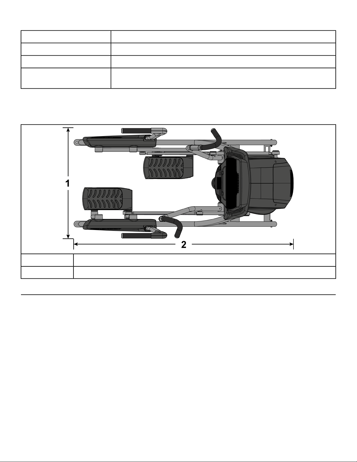
Top View 771AT/772AT
Dimensions
36.28” (92 cm)
1
76.25” (194 cm)2
Choosing and Preparing Site
Before assembling the unit, verify the chosen site meets the following criteria:
• Area is well lit and well ventilated.
• Surface is structurally sound and properly leveled.
• Free area for access to unit and emergency dismount. Minimum clearance is 23.6 inches (0.6 meters).
• Adjacent units may share the free area.
Page 12 of 95
Cybex 771A/771AT, 772A/772AT Arc Trainer Part Number 5771-4 K
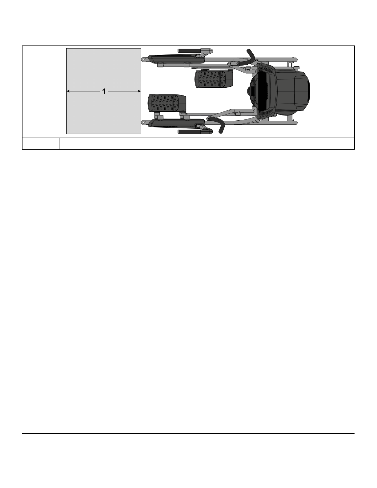
Free Area
23.6”, 0.6m
1
It is the responsibility of the facility owner/owner of the equipment to ensure that there is appropriate
clearance around each machine to allow for safe use and passage.
In compliance with the ADA (American Disabilities Act) there must be clear floor space of at least 30 by
48 inches and be served by an accessible route for at least one of each type of exercise equipment. If
the clear space is enclosed on three sides (e.g., by walls or the equipment itself), the clear space must
be 36 by 48 inches.
All other machines must have a clear floor space of 23" for all access point on the machine.
The dimensions stated in the assembly instructions of this manual include the maximum foot print (in
use) dimensions.
Minimum clearance of 12” (30 cm) between units for proper wireless heart rate signal operation.
Environment
Humidity and Static Electricity
The unit is designed to function normally in an environment with a relative humidity range of 30% to
75%. The unit can be shipped and stored in a relative humidity range of 10% to 90%.
Climatic dry air may cause static electricity. During workout, user may experience a shock due to build
up of static electricity on the body and the discharge path of the unit. If static electricity is experienced,
increase humidity to a comfortable level through the use of a humidifier.
Do not install, use or store the unit in an area of high humidity, such as in the vicinity of a steam room,
sauna, indoor pool or outdoors. Exposure to extensive water vapor, chlorine and/or bromine could
adversely affect the electronics as well as other parts of the unit.
Temperature
The unit is designed to function normally in an environment with an ambient temperature range of 50°
F (10° C) to 104° F (40° C). The unit can be shipped and stored in an environment with an ambient
temperature range of 32° F (0° C) to 140° F (60° C).
Electrical Power Requirements
The AC power kit is optional.
Page 13 of 95
Cybex 771A/771AT, 772A/772AT Arc Trainer Part Number 5771-4 K

The E3 View Monitor is supplied with a power cord,
Use Cybex supplied AC power kit only. Consult an electrician with any questions.
Verify the unit is connected to an outlet having the same configuration as the plug.
Verify connection is a grounded circuit. Do not use a ground-plug adapter to adapt the 3-prong power
cord to a non-grounded electrical outlet.
Verify power supply is compliant with local building codes.
Assembly Procedure 771A/772A
Two people will be required for this procedure.
Read and understand all instructions thoroughly before assembling this unit. Check all items
carefully. If there is damage, see the Customer Service section of this manual for proper procedure
to return, replace, or reorder parts.
The words "left" and "right" denote the user's orientation.
Verify you have received the correct package
1. Read box label to verify the model number and voltage (optional) match what was ordered.
2. Verify paint color matches what was ordered.
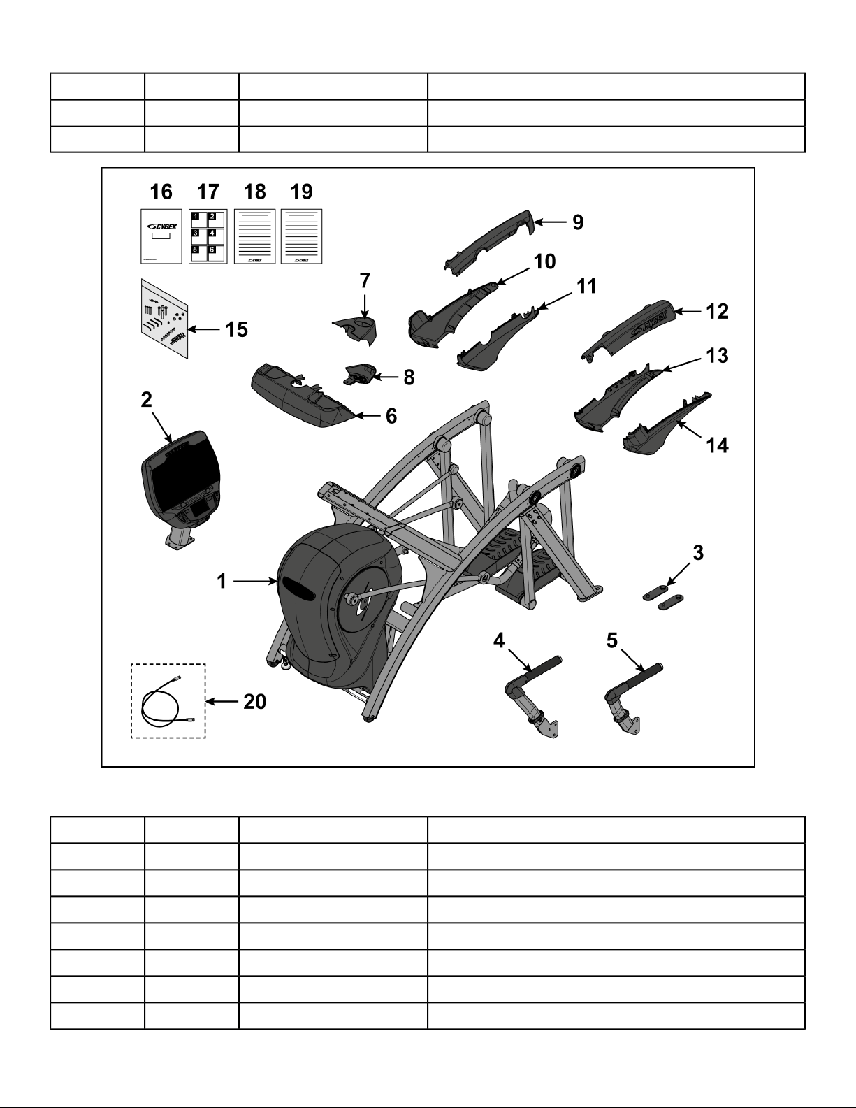
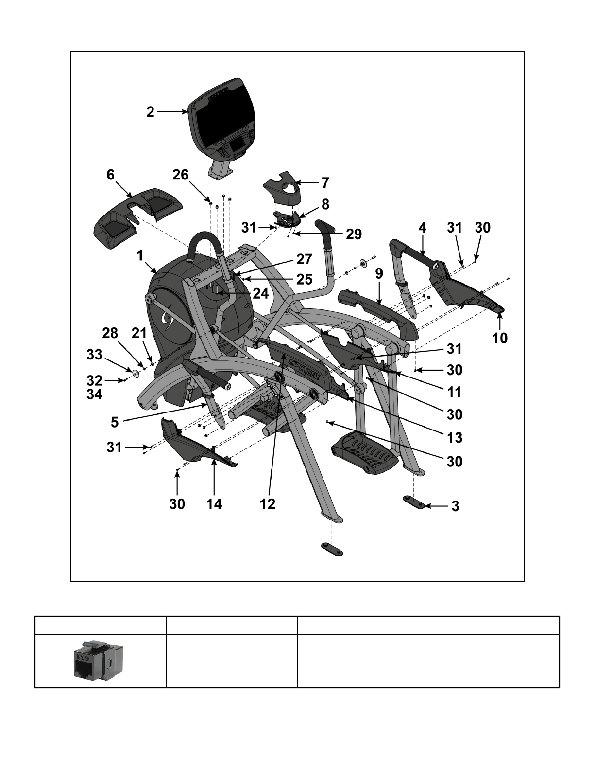
Verify parts list shown below
DescriptionPart NumberQuantityItem
Base assemblyVaries11
Console assemblyVaries12
Foot pad12090-32223
Handle, Right-14
Handle, Left-15
Base, Accessory tray770A-31616
Cover, Top, Accessory tray770A-31717
Cover, Bottom, Accessory tray770A-31818
Cover, Rear, Top, Right770A-32219
Cover, Rear, Outer, Right770A-323110
Cover, Rear, Inner, Right770A-324111
Cover, Rear, Top, Left770A-319112
Cover, Rear, Inner, Left770A-321113
Cover, Rear, Outer, Left770A-320114
Hardware pack-115
Owner’s Manual5771-X116
Page 14 of 95
Cybex 771A/771AT, 772A/772AT Arc Trainer Part Number 5771-4 K
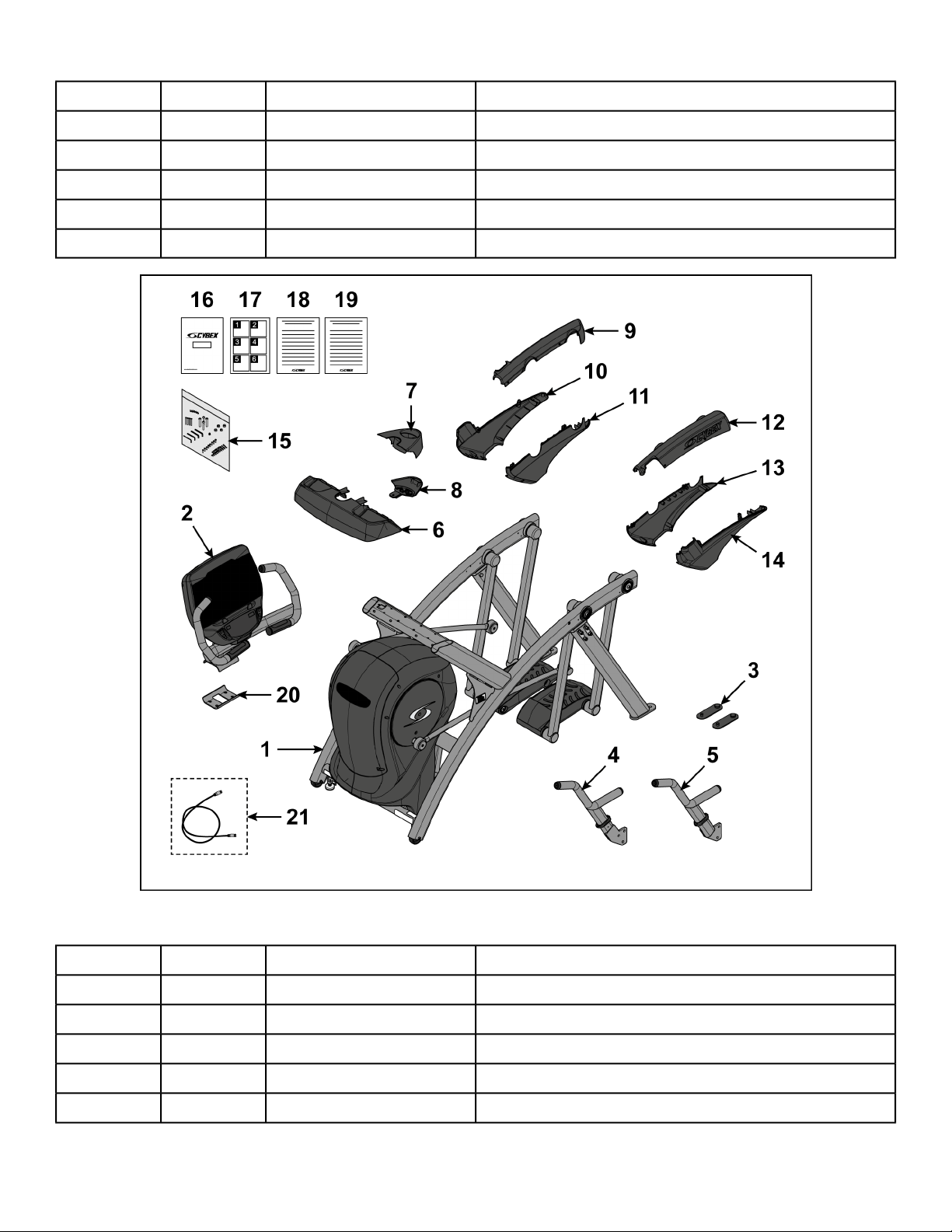
DescriptionPart NumberQuantityItem
Assembly poster771A-404117
Commercial Arc warranty sheet770A-415118
Consumer Arc warranty sheet770A-416119
Bracket, Lower, Display mount770A-310120
Cable, 6’, Coax (E3 View Monitor option)770A-427121
Hardware
DescriptionPart NumberQuantityItem
7/32” Allen WrenchBK030204122
BHSCS .375-16 × 2.50”HC700430423
Grommet, NylonHF540200124
Locknut, .375-16 NylonHN704901425
Tap Sc 10-12 × 2.00 Pn Hd PhilHT592526426
Page 15 of 95
Cybex 771A/771AT, 772A/772AT Arc Trainer Part Number 5771-4 K
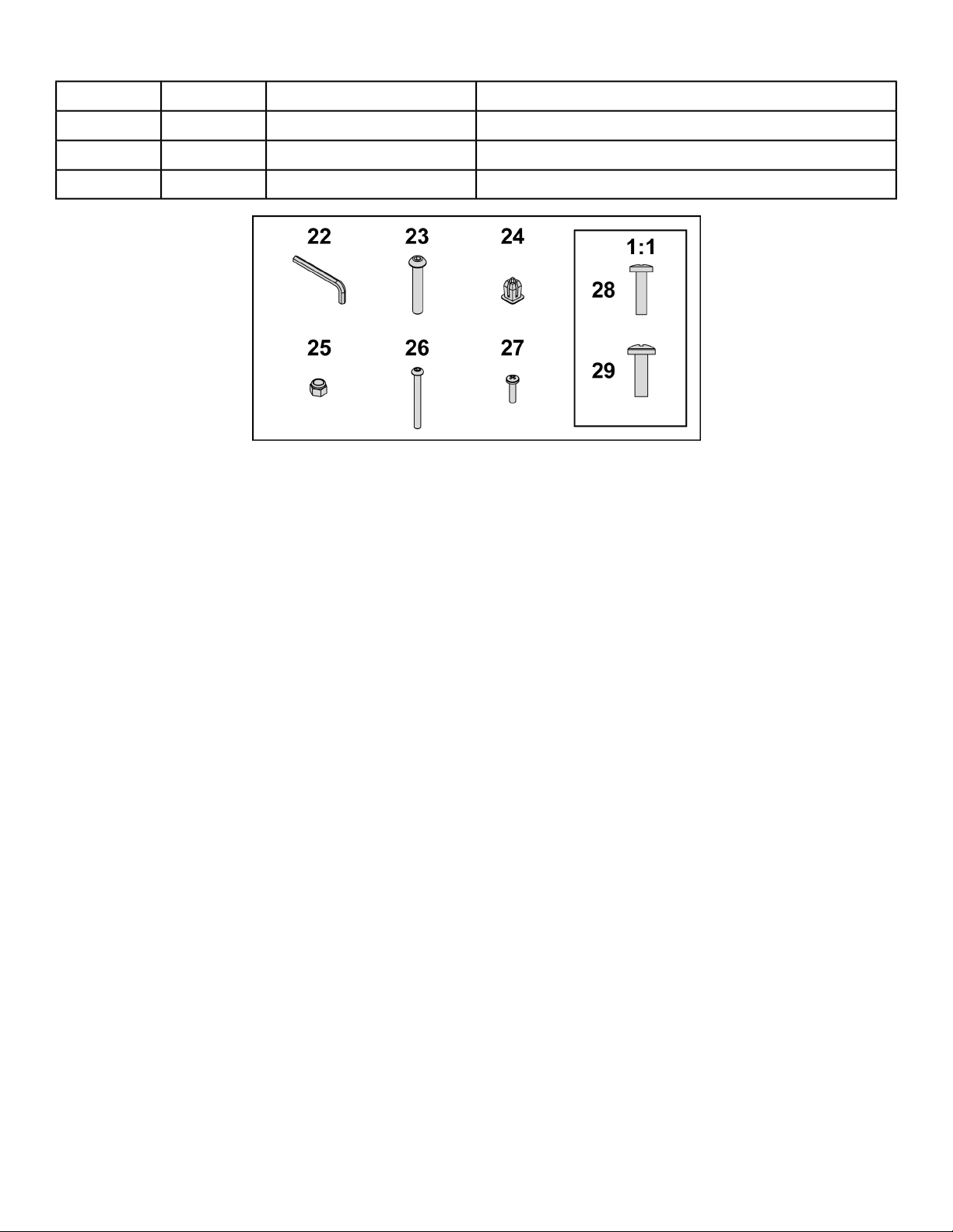
DescriptionPart NumberQuantityItem
Screw, Pan Head Phillips, #6 × .50”HT532512227
Screw, Pan Head Phillips, 8-16 × .50”HT5525121928
Screw, Pan Head Phillips, 10-24 × .75”HT572515829
Page 16 of 95
Cybex 771A/771AT, 772A/772AT Arc Trainer Part Number 5771-4 K
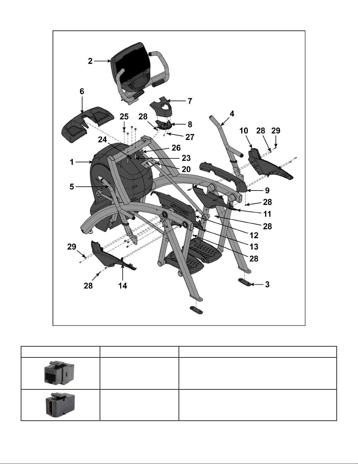
Optional audio visual components
DescriptionPart NumberCoupler
Ethernet CouplerOCN-22747
HDMI CouplerOCN-25816
Page 17 of 95
Cybex 771A/771AT, 772A/772AT Arc Trainer Part Number 5771-4 K
Tools Required
• Phillips screwdriver
• Stubby Phillips screwdriver
• 3/16” Allen wrench (included)
• 7/32” Allen wrench (included)
• 9/16” Open end wrench (2)
Lift and move unit
1. Remove large bolts and shipping supports. Keep package material on linkage arms at this time.
This will protect the paint from scratching during assembly.
2. Grasp each rear support leg firmly and lift with one person on each side.
3. Lift the lower rear support legs so the front transport wheels are able to roll on floor.
Use proper lifting methods.
4. Move unit to intended location.
5. Lower rear support legs.
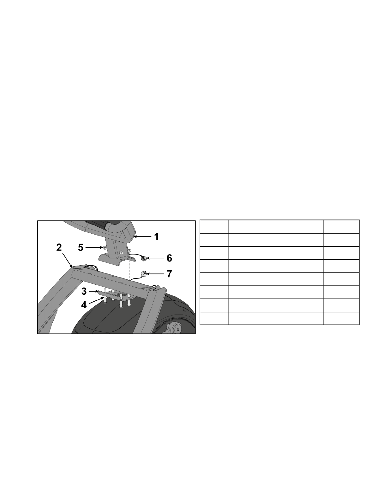
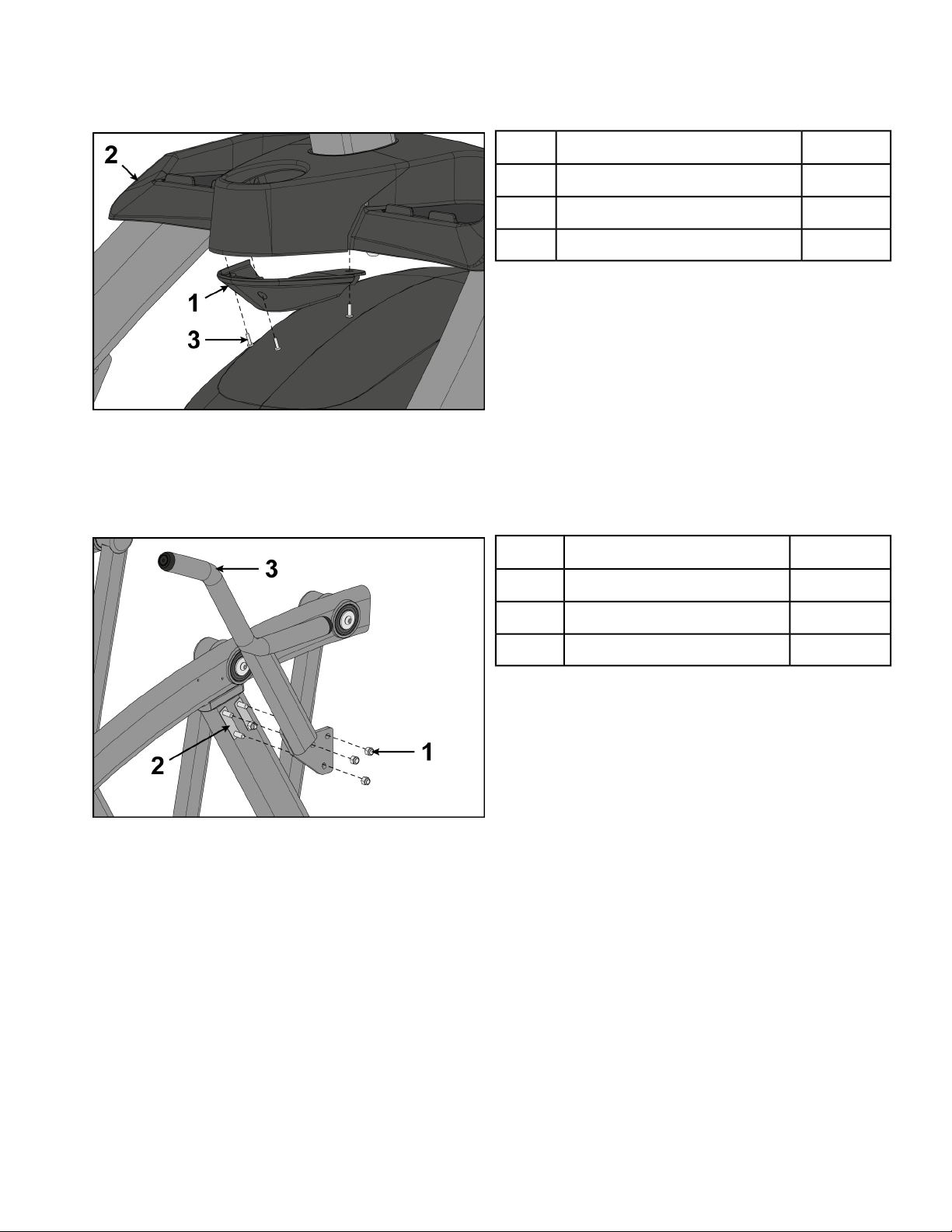
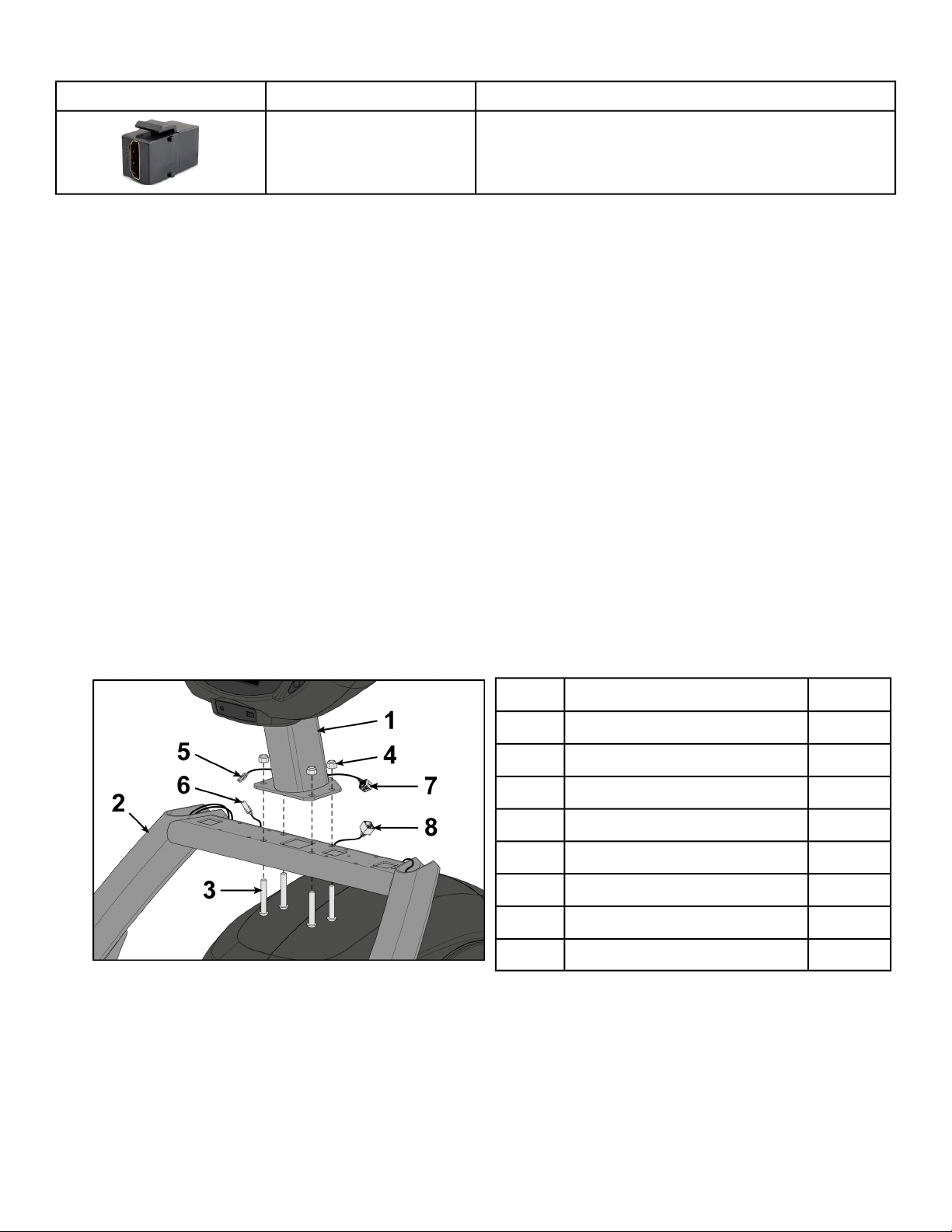
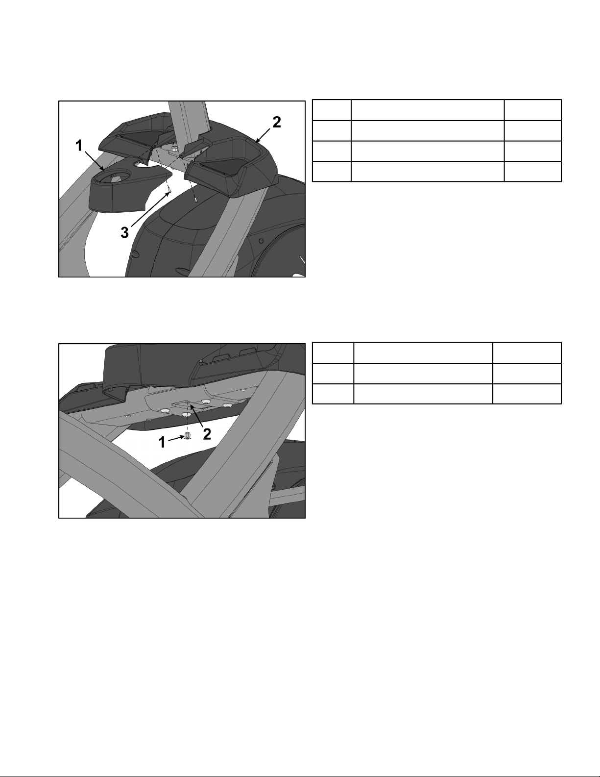
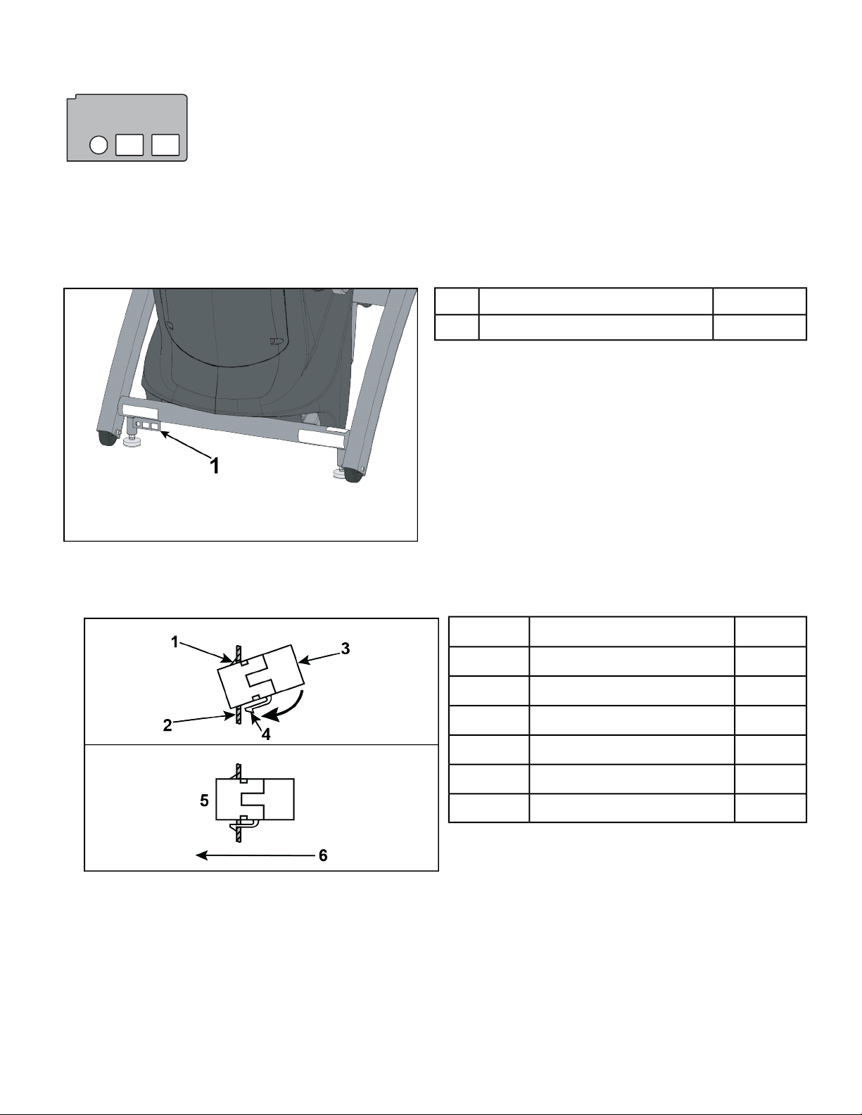
Install console assembly
1. Place the console into position on the frame. Do not pinch cables while lowering the console.
QtyDescription
1Console1
1Frame2
1Lower bracket3
4Bolts4
4Locknuts5
1Upper display cable6
1Lower display cable7
2. Insert (from underneath) the lower bracket and four bolts into the frame and console.
3. Thread the four locknuts onto the bolts by hand.
4. Tighten the four bolts and locknuts with a 7/32” Allen wrench and a 9/16” open-end wrench.
5. Plug the upper display cable into the lower display cable.
Page 18 of 95
Cybex 771A/771AT, 772A/772AT Arc Trainer Part Number 5771-4 K
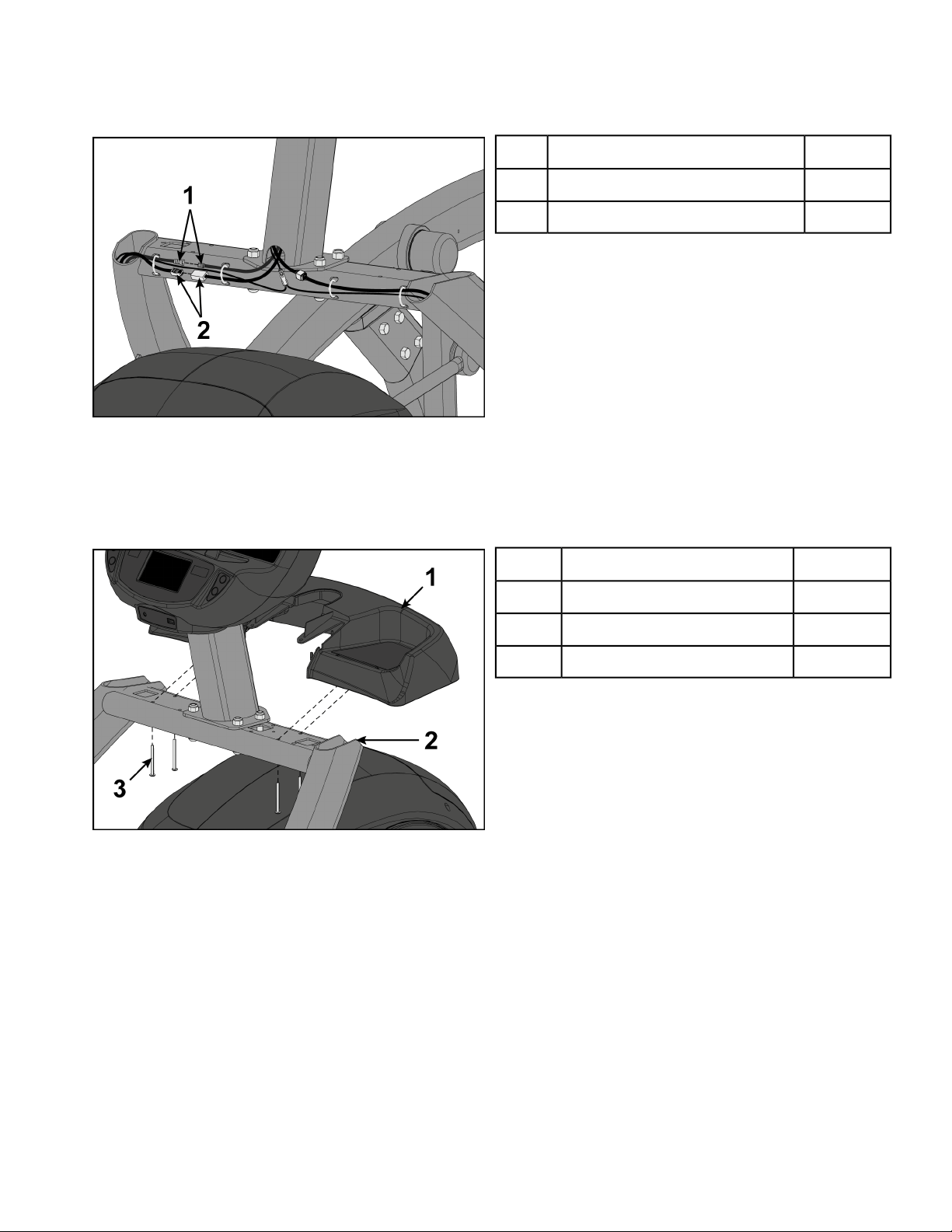
Install optional coax and ethernet cables
1. Plug the coax cable connectors into each other and tighten threaded connector.
Qty.Description
1Coax cable connectors1
1Ethernet cable connectors2
2. Plug the ethernet cable connectors into each other.
Install accessory tray base
Install the four screws securing accessory tray base to frame using a stubby Phillips screwdriver.
QtyDescription
1Accessory tray base1
1Frame2
4Screws3
Page 19 of 95
Cybex 771A/771AT, 772A/772AT Arc Trainer Part Number 5771-4 K

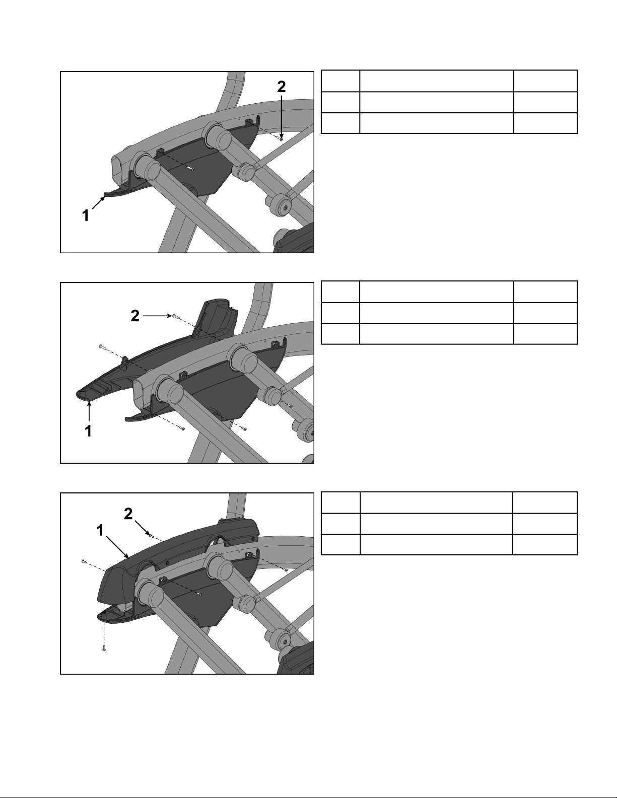
Install accessory tray top
Install the two screws securing accessory tray top to accessory tray base using a stubby Phillips
screwdriver.
QtyDescription
1Accessory tray top1
1Accessory tray base2
2Screws3
Install accessory tray bottom
1. Install the grommet to the frame.
QtyDescription
1Grommet1
1Frame2
Page 20 of 95
Cybex 771A/771AT, 772A/772AT Arc Trainer Part Number 5771-4 K
2. Install the accessory tray bottom to the accessory tray base with three screws using a Phillips
screwdriver.
QtyDescription
1Accessory tray bottom1
1Accessory tray base2
3Screws3
Install handrails
1. Remove three locknuts from the left support leg using two 9/16" open end wrenches. Keep the two
spacers in place.
QtyDescription
3Locknuts1
2Spacers2
1Left handle3
2. Install the left handle and three locknuts using two 9/16" open end wrenches.
Page 21 of 95
Cybex 771A/771AT, 772A/772AT Arc Trainer Part Number 5771-4 K
3. Install the left inner rear cover with two screws using a Phillips screwdriver.
QtyDescription
1Left inner rear cover1
2Screws2
4. Install the left outer rear cover with five screws using a Phillips screwdriver.
QtyDescription
1Left outer rear cover1
5Screws2
5. Install the left top rear cover with five screws using a Phillips screwdriver.
QtyDescription
1Left top rear cover1
5Screws2
Page 22 of 95
Cybex 771A/771AT, 772A/772AT Arc Trainer Part Number 5771-4 K
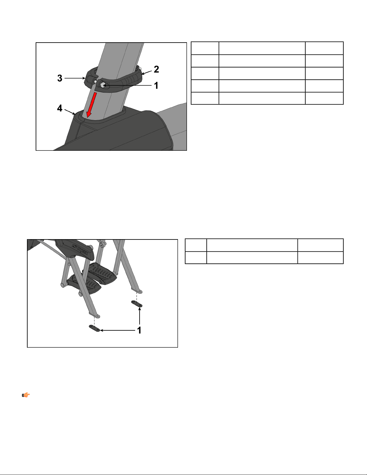
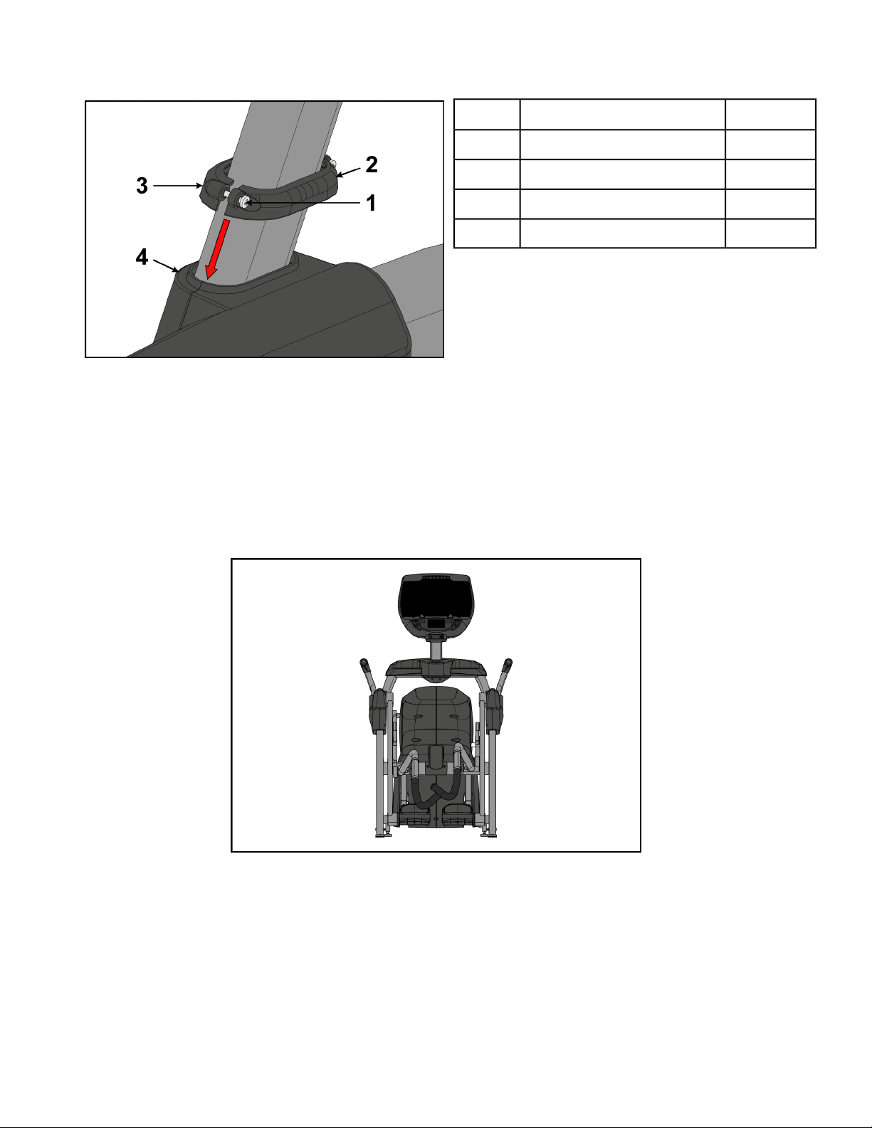
6. Loosen the two screws in the left inner and outer collars using a Phillips screwdriver.
QtyDescription
2Screws1
1Inner collar2
1Outer collar3
1Cover4
7. Slide the inner and outer collars onto the left cover.
8. Insert the tabs of the collars into the slots of the cover.
9. Tighten the two screws using a Phillips screwdriver.
10. Repeat steps 1 through 9 for the right side.
Install foot pads
Have one person lift the unit while a second person places a foot pad under each of the two back feet.
Qty.Description
2Foot pads1
Level unit
This procedure will level the unit by evenly adjusting the weight on the rear feet. Leveling the unit will
eliminate rocking during use.
Note: References to left and right are from the users perspective during use.
1. Verify foot plates are completely stopped.
Page 23 of 95
Cybex 771A/771AT, 772A/772AT Arc Trainer Part Number 5771-4 K
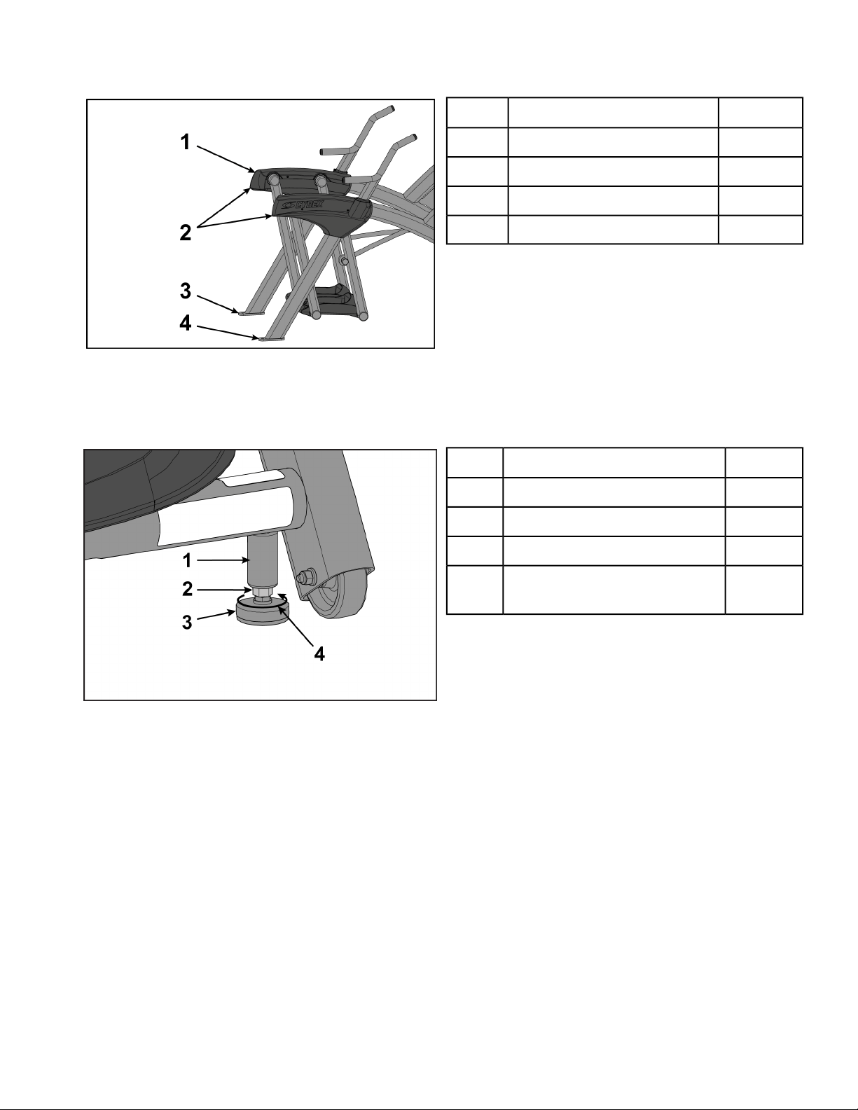
2. Grasp one of the rear covers and slowly lift the rear foot off the floor. Lower rear foot to the floor.
Qty.Description
2Rear cover1
2Lift here2
1Left rear foot3
1Right rear foot4
3. Grasp the other rear cover and slowly lift the rear foot off the floor. Lower rear foot to the floor.
Make note of either rear foot lifting off the floor easier than the other.
If both rear feet lift off the floor evenly, secure both leveling foot jam nuts against the frame post
using a 9/16” open-end wrench. Unit is leveled.
Qty.Description
1Frame post1
1Jam nut2
1Leveling foot3
1
Turn counter-clockwise to
secure
4
Left leveling foot shown
Page 24 of 95
Cybex 771A/771AT, 772A/772AT Arc Trainer Part Number 5771-4 K
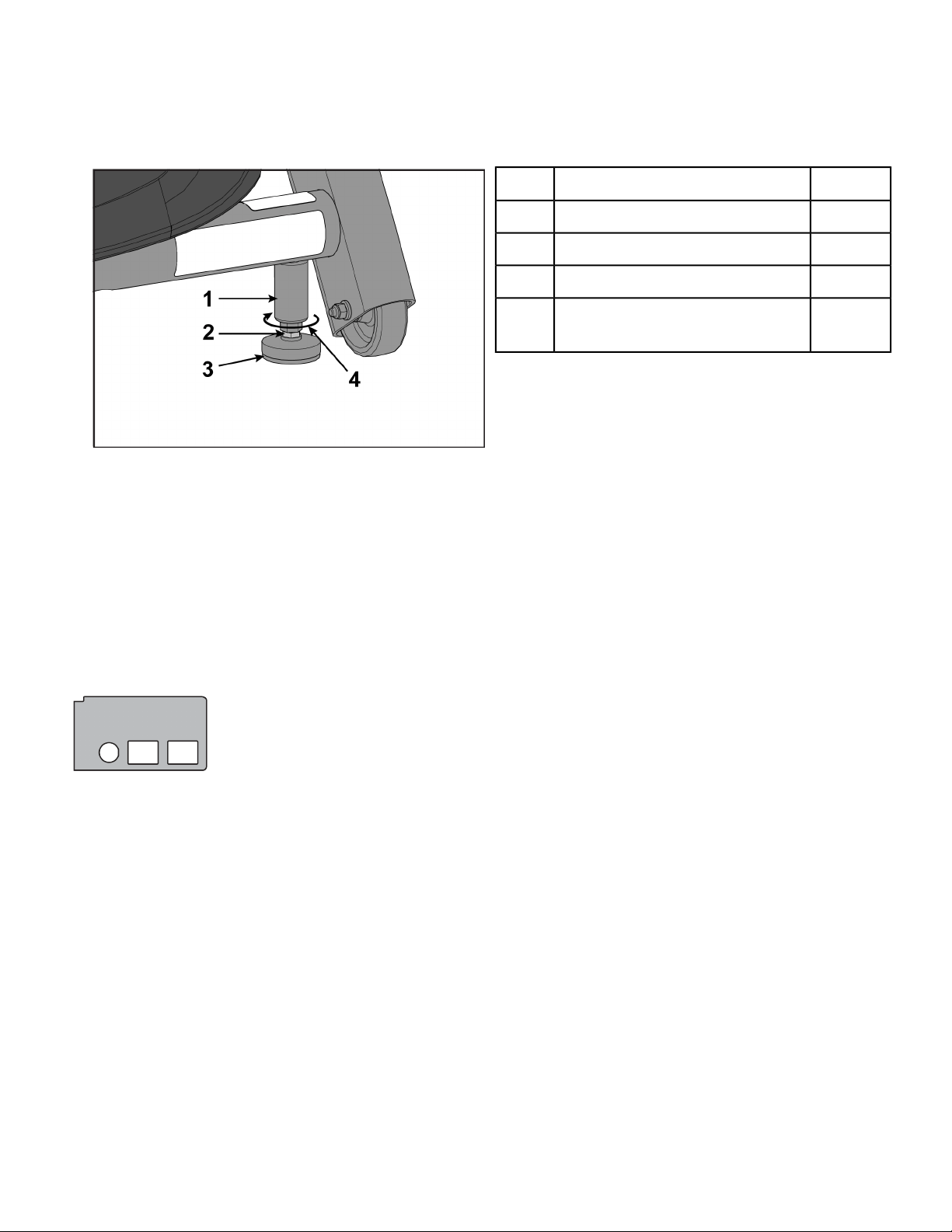
4. Adjust the weight of the rear feet using a 1/2” open-end wrench.
• If the left rear foot lifts up easier, Adjust the right leveling foot nut down.
• If the right rear foot lifts up easier, Adjust the left leveling foot nut down.
Qty.Description
1Frame post1
1Leveling foot nut2
1Leveling foot3
1
Turn clockwise to adjust level-
ing foot down
4
Left leveling foot shown
5. Test the unit again for uneven weight on the rear feet. Adjust leveling foot nuts until each rear foot
lifts with even force.
6. Secure both jam nuts using a 9/16” open-end wrench. Unit is leveled.
Install optional Audio Visual cables
The optional audio visual cables can include combinations of Coax, Ethernet, or HDMI cables.Mounting
plate has three holes for all configuration options:
• Coax Only (EPEM Tuner or MYE CableSAT w/coax)
• Coax and Ethernet (Cybex GO or BV CAB w/coax)
• Ethernet Only (BV CAB TV on a stand)
• HDMI Only (MYE CableSAT w/HDMI)
• Ethernet and HDMI (BV CAB)
Page 25 of 95
Cybex 771A/771AT, 772A/772AT Arc Trainer Part Number 5771-4 K
Qty.Description
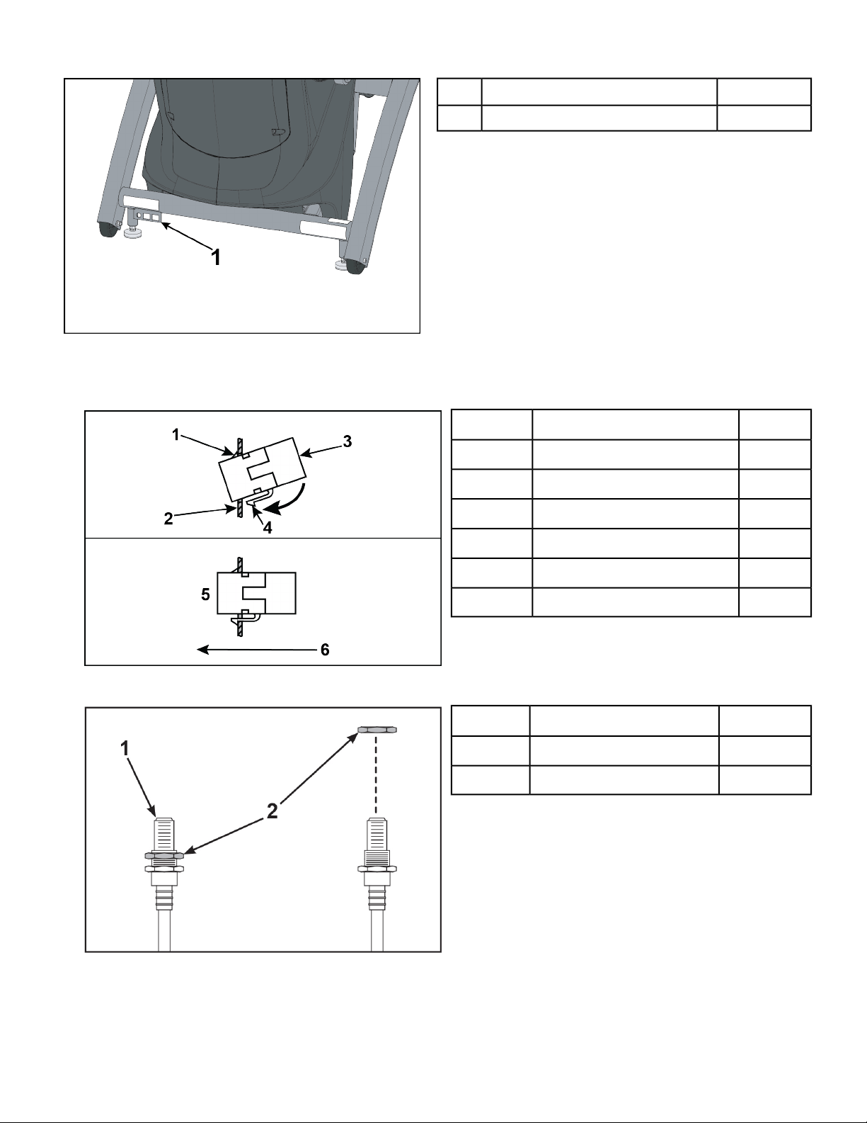
1Mounting plate location1
1. Insert the optional couplers into the mounting plate by hooking the upper tab into the mounting plate
and snapping in the lower tab.
Qty.Description
1Upper tab1
1Mounting plate2
1Ethernet or HDMI coupler3
1Lower tab4
1Installed5
1Front of unit6
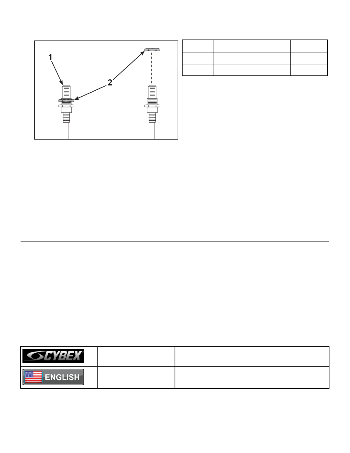
2. Remove the nut at the end of the coax cable.
Qty.Description
1Coax cable1
1Nut2
3. Insert the coax cable into the D-shaped hole in the mounting plate on the front of the unit.
4. Thread the nut removed in step 2 onto the coax cable.
Page 26 of 95
Cybex 771A/771AT, 772A/772AT Arc Trainer Part Number 5771-4 K

5. Install the coax cable to the mounting plate on the front of the unit using a 14 mm open end wrench.
6. Plug the Ethernet or HDMI cable into the coupler on the front of the unit.
Visually inspect unit
1. Remove any packing material from unit.
2. Examine the unit to ensure that the assembly is correct and complete.
Assembly Procedure 771AT/772AT
Two people will be required for this procedure.
Read and understand all instructions thoroughly before assembling this unit. Check all items
carefully. If there is damage, see the Customer Service section of this manual for proper procedure
to return, replace, or reorder parts.
The words "left" and "right" denote the user's orientation.
Verify you have received the correct package
1. Read box label to verify the model number and voltage (optional) match what was ordered.
2. Verify paint color matches what was ordered.
Verify parts list shown below
DescriptionPart NumberQuantityItem
Base assemblyVaries11
Console assemblyVaries12
Foot pad12090-32223
Handle, RightNA14
Handle, LeftNA15
Base, Accessory tray770A-31616
Cover, Top, Accessory tray770A-31717
Cover, Bottom, Accessory tray770A-31818
Cover, Rear, Top, Right770A-32219
Cover, Rear, Outer, Right770A-323110
Cover, Rear, Inner, Right770A-324111
Cover, Rear, Top, Left770A-319112
Cover, Rear, Inner, Left770A-321113
Cover, Rear, Outer, Left770A-320114
Hardware packNA115
Owner’s Manual5771-X116
Assembly poster771AT-316117
Commercial Arc warranty sheet770A-415118
Page 27 of 95
Cybex 771A/771AT, 772A/772AT Arc Trainer Part Number 5771-4 K
DescriptionPart NumberQuantityItem
Consumer Arc warranty sheet770A-416119
Cable, 6’, Coax (E3 View Monitor option)770A-427120
Hardware
DescriptionPart NumberQuantityItem
Flange Spacer600A-311221
3/16” Allen WrenchBK030201122
7/32” Allen WrenchBK030204223
BHSCS .375-16 × 2.25”HC700428424
Grommet, NylonHF540200125
Locknut, .375-16 NylonHN704901426
Tap Sc 10-12 × 2.00 Pn Hd PhilHT592526427
Page 28 of 95
Cybex 771A/771AT, 772A/772AT Arc Trainer Part Number 5771-4 K
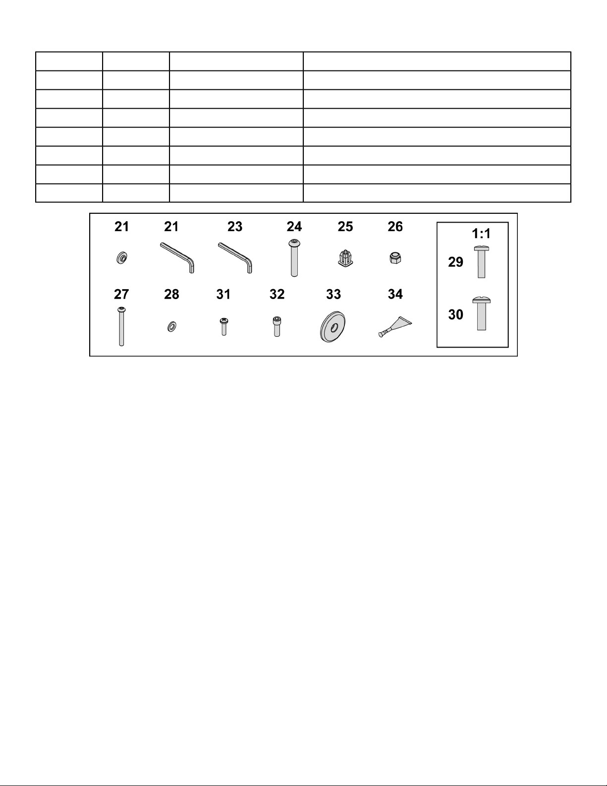
DescriptionPart NumberQuantityItem
Washer, Flat .281 ID × .500 OD × .062”HS307601228
Screw, Pan Head Phillips, #6 × .50”HT532512229
Screw, Pan Head Phillips, 8-16 × .50”HT5525121930
Screw, Pan Head Phillips, 10-24 × .75”HT572515831
SHCS .250-20 UNC-3A SSHX622815232
Linkage Rod Cap 2.00 OD (1 extra)PL-16535333
LoctiteYA000201134
Page 29 of 95
Cybex 771A/771AT, 772A/772AT Arc Trainer Part Number 5771-4 K
Optional audio visual components
DescriptionPart NumberCoupler
Ethernet CouplerOCN-22747
Page 30 of 95
Cybex 771A/771AT, 772A/772AT Arc Trainer Part Number 5771-4 K
DescriptionPart NumberCoupler
HDMI CouplerOCN-25816
Tools Required
• Phillips screwdriver
• Stubby Phillips screwdriver
• 3/16” Allen wrench (included)
• 7/32” Allen wrench (2) (included)
• 9/16” Open end wrench (2)
Lift and move unit
1. Remove large bolts and shipping supports. Keep package material on linkage arms at this time.
This will protect the paint from scratching during assembly.
2. Grasp each rear support leg firmly and lift with one person on each side.
3. Lift the lower rear support legs so the front transport wheels are able to roll on floor.
Use proper lifting methods.
4. Move unit to intended location.
5. Lower rear support legs.
Install console assembly
1. Place the console into position on the frame. Do not pinch cables while lowering the console.
QtyDescription
1Console1
1Frame2
4Bolts3
4Locknuts4
1Upper heart rate cable5
1Lower heart rate cable6
1Upper display cable7
1Lower display cable8
2. Insert (from underneath) the four bolts into the frame and console.
3. Thread the four locknuts onto the bolts by hand.
4. Tighten the four bolts and locknuts with a 7/32” Allen wrench and a 9/16” open-end wrench.
5. Plug the upper heart rate cable into the lower heart rate cable.
6. Plug the upper display cable into the lower display cable.
Page 31 of 95
Cybex 771A/771AT, 772A/772AT Arc Trainer Part Number 5771-4 K
Install optional coax and ethernet cables
1. Plug the coax cable connectors into each other and tighten threaded connector.
Qty.Description
1Coax cable connectors1
1Ethernet cable connectors2
2. Plug the ethernet cable connectors into each other.
Install accessory tray base
Install the four screws securing accessory tray base to frame using a Phillips screwdriver.
QtyDescription
1Accessory tray base1
1Frame2
4Screws3
Page 32 of 95
Cybex 771A/771AT, 772A/772AT Arc Trainer Part Number 5771-4 K
Install accessory tray top
Install the two screws securing accessory tray top to accessory tray base using a stubby Phillips
screwdriver.
QtyDescription
1Accessory tray top1
1Accessory tray base2
2Screws3
Install accessory tray bottom
1. Install the grommet to the frame.
QtyDescription
1Grommet1
1Frame2
Page 33 of 95
Cybex 771A/771AT, 772A/772AT Arc Trainer Part Number 5771-4 K

2. Install the accessory tray bottom to the accessory tray base with three screws using a Phillips
screwdriver.
QtyDescription
1Accessory tray bottom1
1Accessory tray base2
3Screws3
Install handrails
1. Remove three locknuts from the left support leg using two 9/16" open end wrenches. Keep the two
spacers in place.
QtyDescription
3Locknuts1
2Spacers2
1Left handle3
2. Install the left handle and three locknuts using two 9/16" open end wrenches.
Page 34 of 95
Cybex 771A/771AT, 772A/772AT Arc Trainer Part Number 5771-4 K
3. Install the left inner rear cover with two screws using a Phillips screwdriver.
QtyDescription
1Left inner rear cover1
2Screws2
4. Install the left outer rear cover with five screws using a Phillips screwdriver.
QtyDescription
1Left outer rear cover1
5Screws2
5. Install the left top rear cover with five screws using a Phillips screwdriver.
QtyDescription
1Left top rear cover1
5Screws2
Page 35 of 95
Cybex 771A/771AT, 772A/772AT Arc Trainer Part Number 5771-4 K
6. Loosen the two screws in the right inner and outer collars using a Phillips screwdriver.
QtyDescription
2Screws1
1Inner collar2
1Outer collar3
1Cover4
7. Slide the inner and outer collars onto the right covers.
8. Insert the tabs of the collars into the slots of the cover.
9. Tighten the two screws using a Phillips screwdriver.
10. Repeat steps 1 through 9 for the right side.
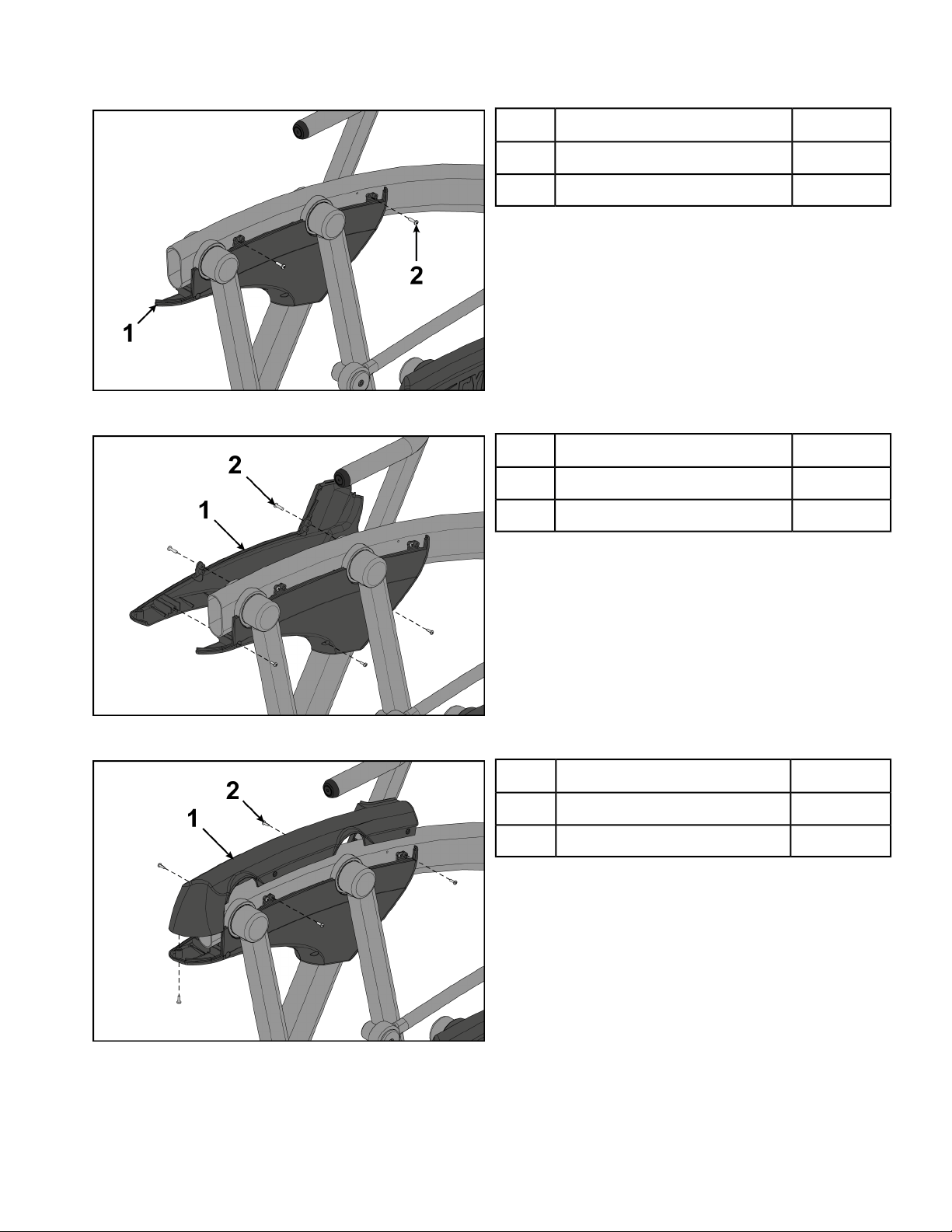
Remove left and right handle assembly
The left and right handle assemblies are shipped in rotated positions. The handle assemblies must be
removed and rotated 180 degrees for proper setup and assembly.
Page 36 of 95
Cybex 771A/771AT, 772A/772AT Arc Trainer Part Number 5771-4 K
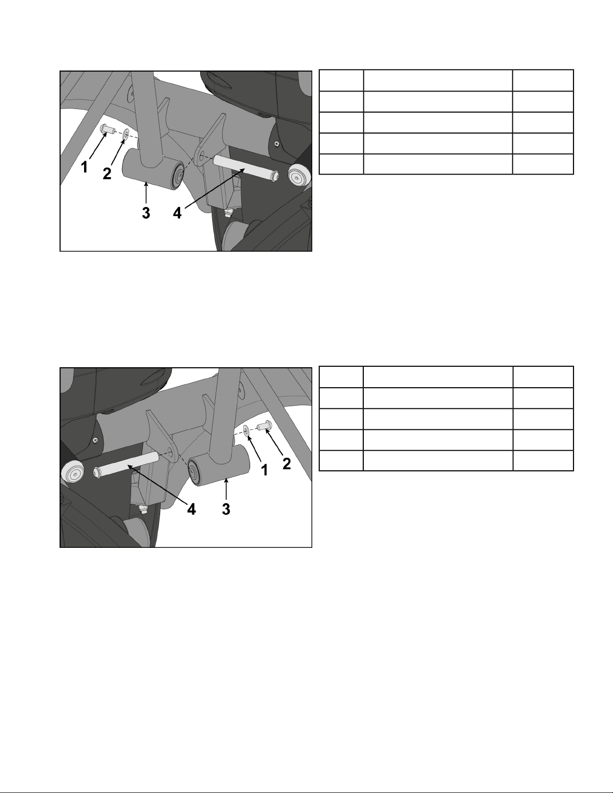
1. Remove a screw and washer from the left handle assembly using two 7/32” Allen wrenches.
Qty.Description
1Screw1
1Washer2
1Left handle3
1Pivot pin assembly4
2. Slide pivot pin assembly out and remove left handle assembly.
3. Rotate left handle assembly 180 degrees.
4. Apply Loctite to threads inside the pivot pin and screw.
5. Place left handle assembly in position and slide pivot pin assembly back in place.
6. Install the screw and washer to the left handle assembly using two 7/32” Allen wrenches.
7. Remove a screw and washer from the right handle assembly using two 7/32” Allen wrenches.
Qty.Description
1Washer1
1Screw2
1Right handle3
1Pivot pin assembly4
8. Slide pivot pin assembly out and remove right handle assembly.
9. Rotate right handle assembly 180 degrees.
10. Apply Loctite to threads inside the pivot pin and screw.
11. Place right handle assembly in position and slide pivot pin assembly back in place.
12. Install the screw and washer to the right handle assembly using two 7/32” Allen wrenches.
Page 37 of 95
Cybex 771A/771AT, 772A/772AT Arc Trainer Part Number 5771-4 K
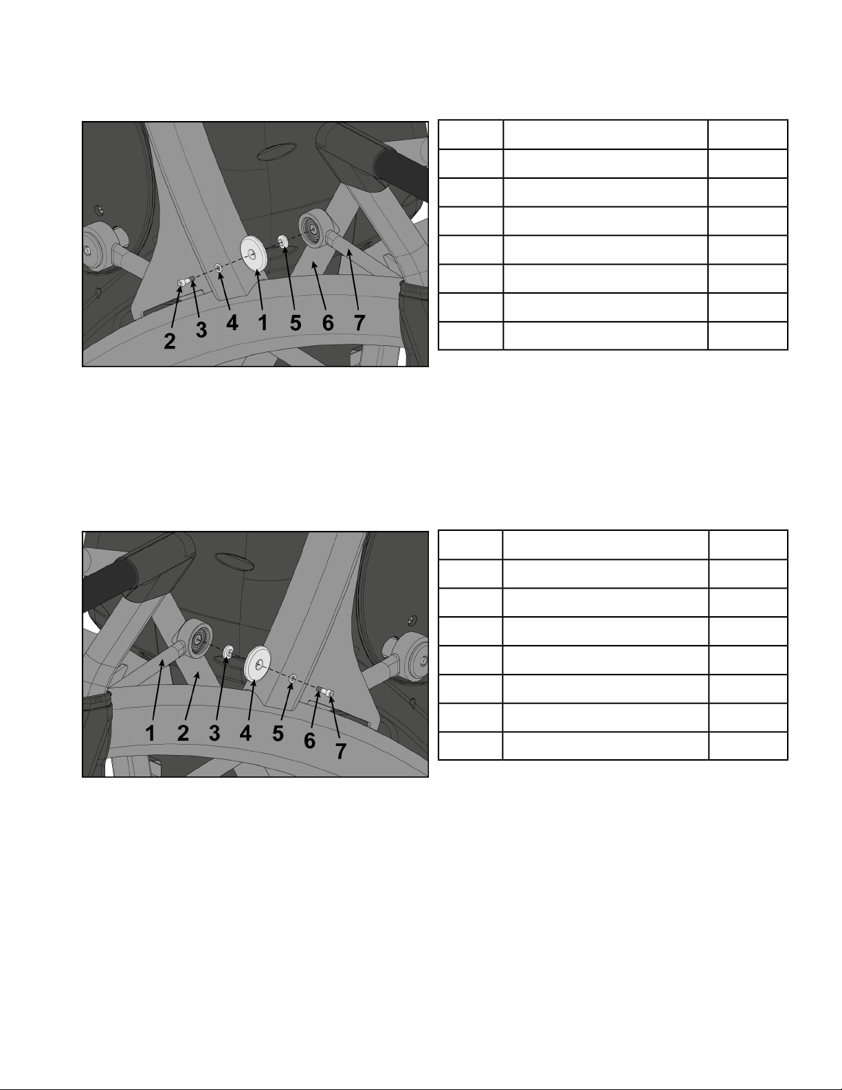
Install left linkage rod
1. Pivot left handle assembly up and slide left linkage rod onto left arm.
Qty.Description
1Linkage rod cap1
1Screw2
1Loctite3
1Washer4
1Flange spacer5
1Left arm6
1Left linkage rod7
2. Place a drop of Loctite onto the screw.
3. Install the screw, washer, linkage rod cap, and flange spacer using a 3/16” Allen wrench.
4. Tighten screw to a minimum of 90 in/lbs.
Install right linkage rod
1. Pivot right handle assembly up and slide left linkage rod onto left arm.
Qty.Description
1Right linkage rod1
1Right arm2
1Flange spacer3
1Linkage rod cap4
1Washer5
1Loctite6
1Screw7
2. Place a drop of Loctite onto the screw.
3. Install the screw, washer, linkage rod cap, and flange spacer using a 3/16” Allen wrench.
Page 38 of 95
Cybex 771A/771AT, 772A/772AT Arc Trainer Part Number 5771-4 K
4. Tighten screw to a minimum of 90 in/lbs.
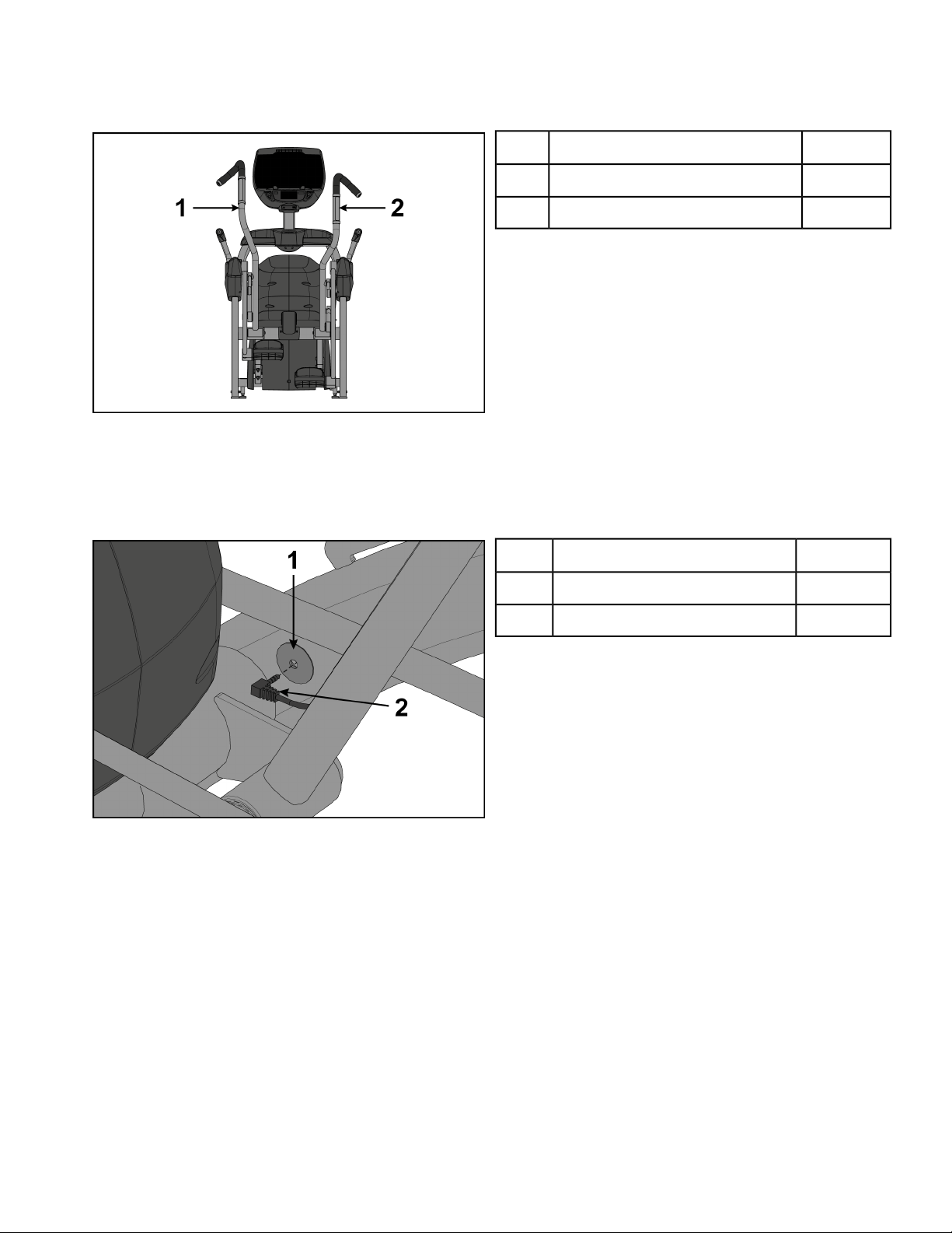
Verify handle assemblies are now installed in the correct position.
Qty.Description
1Left handle assembly1
1Right handle assembly2
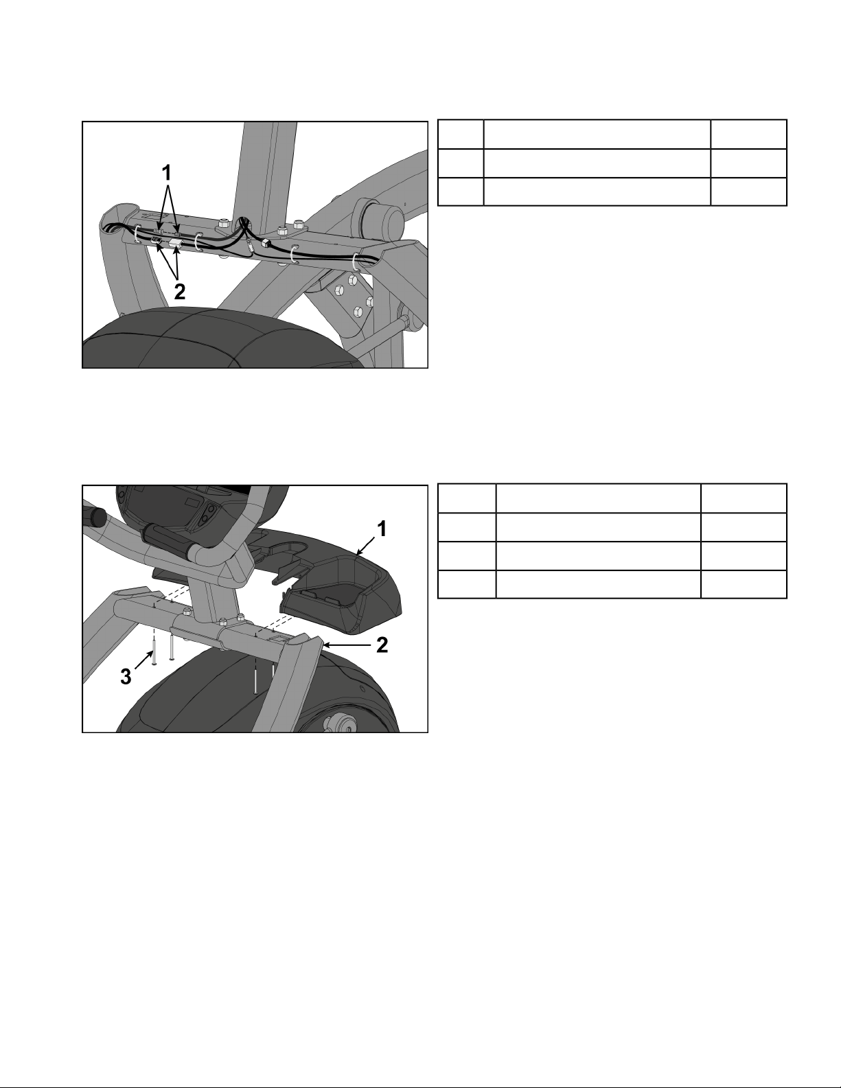
Install contact heart rate cable
1. Plug right heart rate cable into main frame socket.
Position plug so handle does not rub cable during operation.
Qty.Description
1Main frame socket1
1Heart rate wire2
2. Plug left heart rate cable into main frame socket.
Position plug so handle does not rub cable during operation.
Verify heart rate cables do not rub on handle during operation.
Install foot pads
Have one person lift the unit while a second person places a foot pad under each of the two back feet.
Page 39 of 95
Cybex 771A/771AT, 772A/772AT Arc Trainer Part Number 5771-4 K
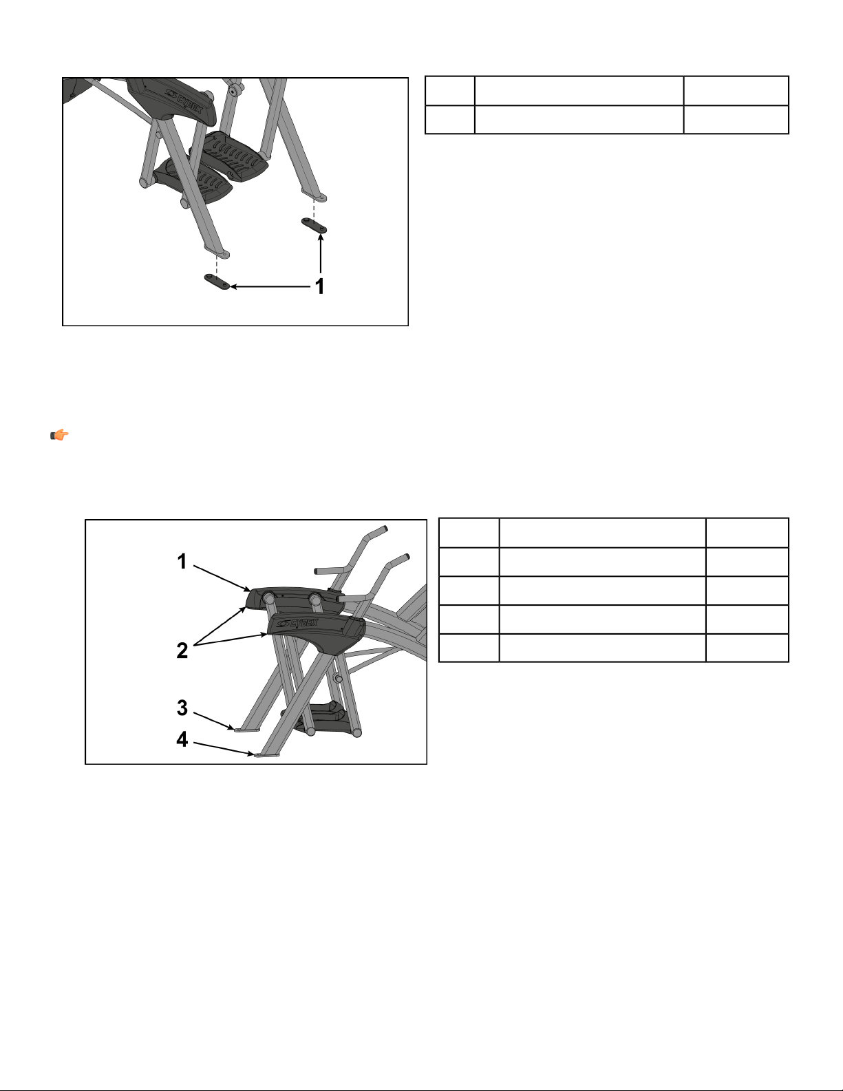
Qty.Description
2Foot pads1
Level unit
This procedure will level the unit by evenly adjusting the weight on the rear feet. Leveling the unit will
eliminate rocking during use.
Note: References to left and right are from the users perspective during use.
1. Verify foot plates are completely stopped.
2. Grasp one of the rear covers and slowly lift the rear foot off the floor. Lower rear foot to the floor.
Qty.Description
2Rear cover1
2Lift here2
1Left rear foot3
1Right rear foot4
Page 40 of 95
Cybex 771A/771AT, 772A/772AT Arc Trainer Part Number 5771-4 K
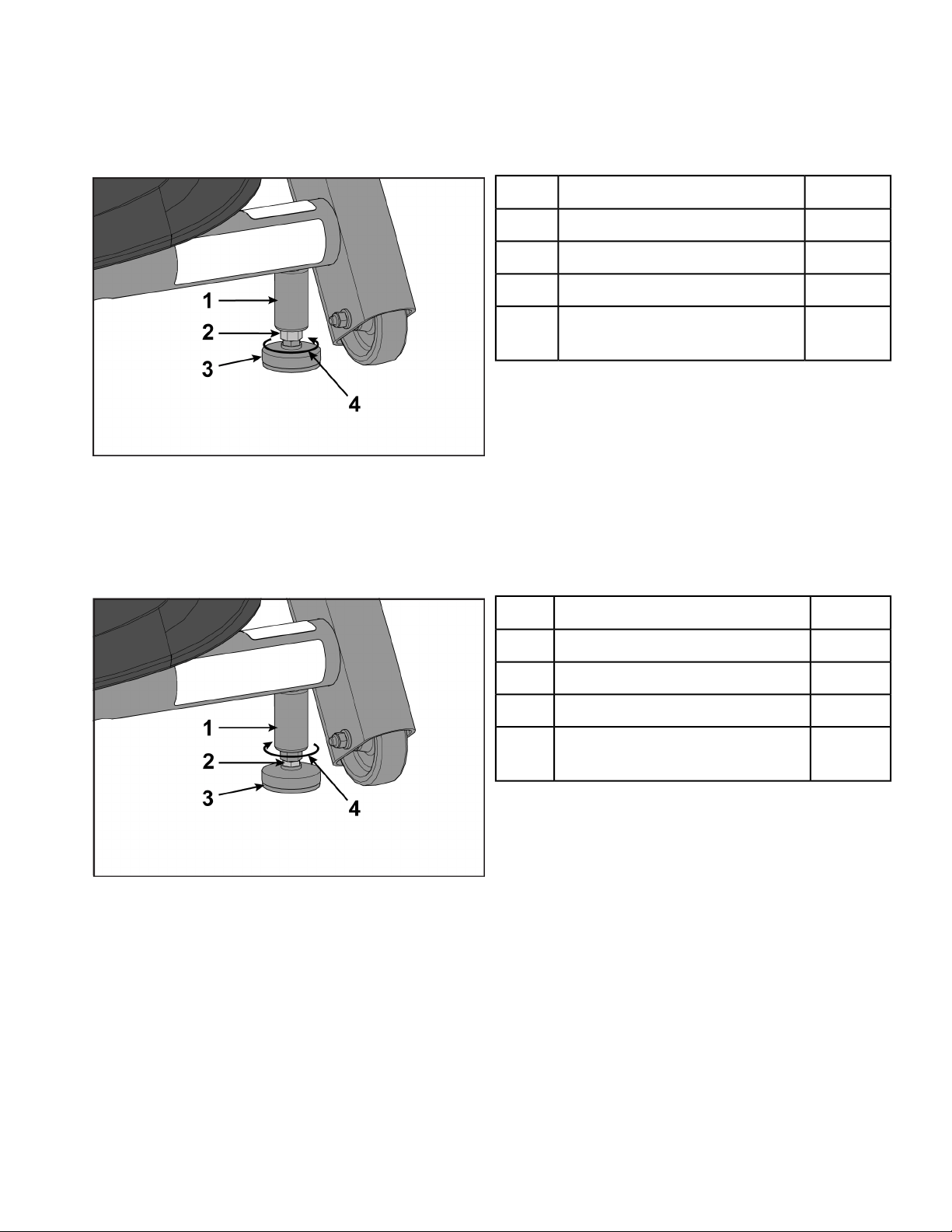
3. Grasp the other rear cover and slowly lift the rear foot off the floor. Lower rear foot to the floor.
Make note of either rear foot lifting off the floor easier than the other.
If both rear feet lift off the floor evenly, secure both leveling foot jam nuts against the frame post
using a 9/16” open-end wrench. Unit is leveled.
Qty.Description
1Frame post1
1Jam nut2
1Leveling foot3
1
Turn counter-clockwise to
secure
4
Left leveling foot shown
4. Adjust the weight of the rear feet using a 1/2” open-end wrench.
• If the left rear foot lifts up easier, Adjust the right leveling foot nut down.
• If the right rear foot lifts up easier, Adjust the left leveling foot nut down.
Qty.Description
1Frame post1
1Leveling foot nut2
1Leveling foot3
1
Turn clockwise to adjust level-
ing foot down
4
Left leveling foot shown
5. Test the unit again for uneven weight on the rear feet. Adjust leveling foot nuts until each rear foot
lifts with even force.
6. Secure both jam nuts using a 9/16” open-end wrench. Unit is leveled.
Install optional Audio Visual cables
The optional audio visual cables can include combinations of Coax, Ethernet, or HDMI cables.Mounting
plate has three holes for all configuration options:
Page 41 of 95
Cybex 771A/771AT, 772A/772AT Arc Trainer Part Number 5771-4 K
• Coax Only (EPEM Tuner or MYE CableSAT w/coax)
• Coax and Ethernet (Cybex GO or BV CAB w/coax)
• Ethernet Only (BV CAB TV on a stand)
• HDMI Only (MYE CableSAT w/HDMI)
• Ethernet and HDMI (BV CAB)
Qty.Description
1Mounting plate location1
1. Insert the optional couplers into the mounting plate by hooking the upper tab into the mounting plate
and snapping in the lower tab.
Qty.Description
1Upper tab1
1Mounting plate2
1Ethernet or HDMI coupler3
1Lower tab4
1Installed5
1Front of unit6
Page 42 of 95
Cybex 771A/771AT, 772A/772AT Arc Trainer Part Number 5771-4 K
2. Remove the nut at the end of the coax cable.
Qty.Description
1Coax cable1
1Nut2
3. Insert the coax cable into the D-shaped hole in the mounting plate on the front of the unit.
4. Thread the nut removed in step 2 onto the coax cable.
5. Install the coax cable to the mounting plate on the front of the unit using a 14 mm open end wrench.
6. Plug the Ethernet or HDMI cable into the coupler on the front of the unit.
Visually inspect unit
1. Remove any packing material from unit.
2. Examine the unit to ensure that the assembly is correct and complete.
Setup
Use the following instructions to setup the unit.
1. Plug the optional power cord or E3 View Monitor power cord (E3 View Monitor units only) into a
power outlet from a grounded circuit.
Coil up the remainder of the power cord and place it out of the way. The control panel will light up
and be in the Dormant Mode.
2. Hold the handrails to steady self while stepping into the foot plates.
3. Begin striding.
Initial setup
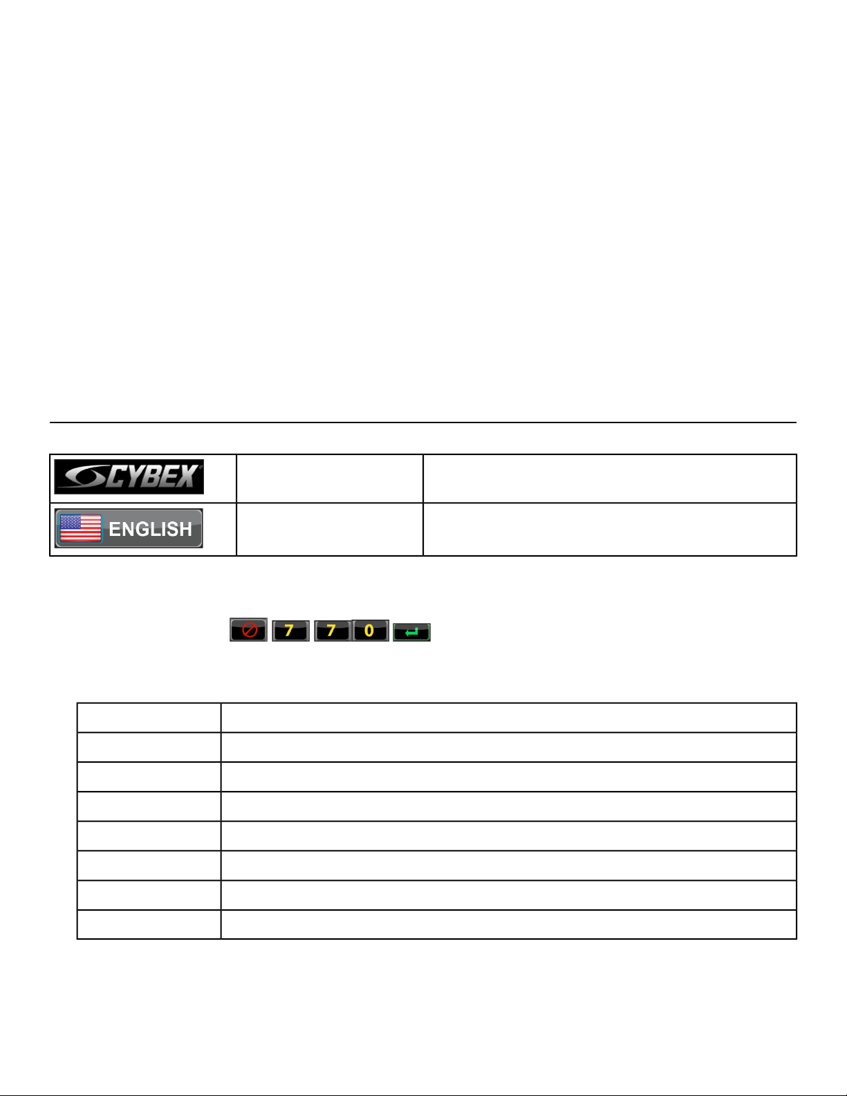
Perform this procedure during the installation of the unit. Once complete, refer to Setup Options below.
Press and hold Cybex logo for 6 seconds to access
Screen Lock and Toolbox.
CYBEX LOGO
Press and hold language logo for 6 seconds to ac-
cess Screen Lock and Toolbox.
LANGUAGE ICON
1. Tap the Access Toolbox icon to display the Access to Toolbox login screen.
Page 43 of 95
Cybex 771A/771AT, 772A/772AT Arc Trainer Part Number 5771-4 K
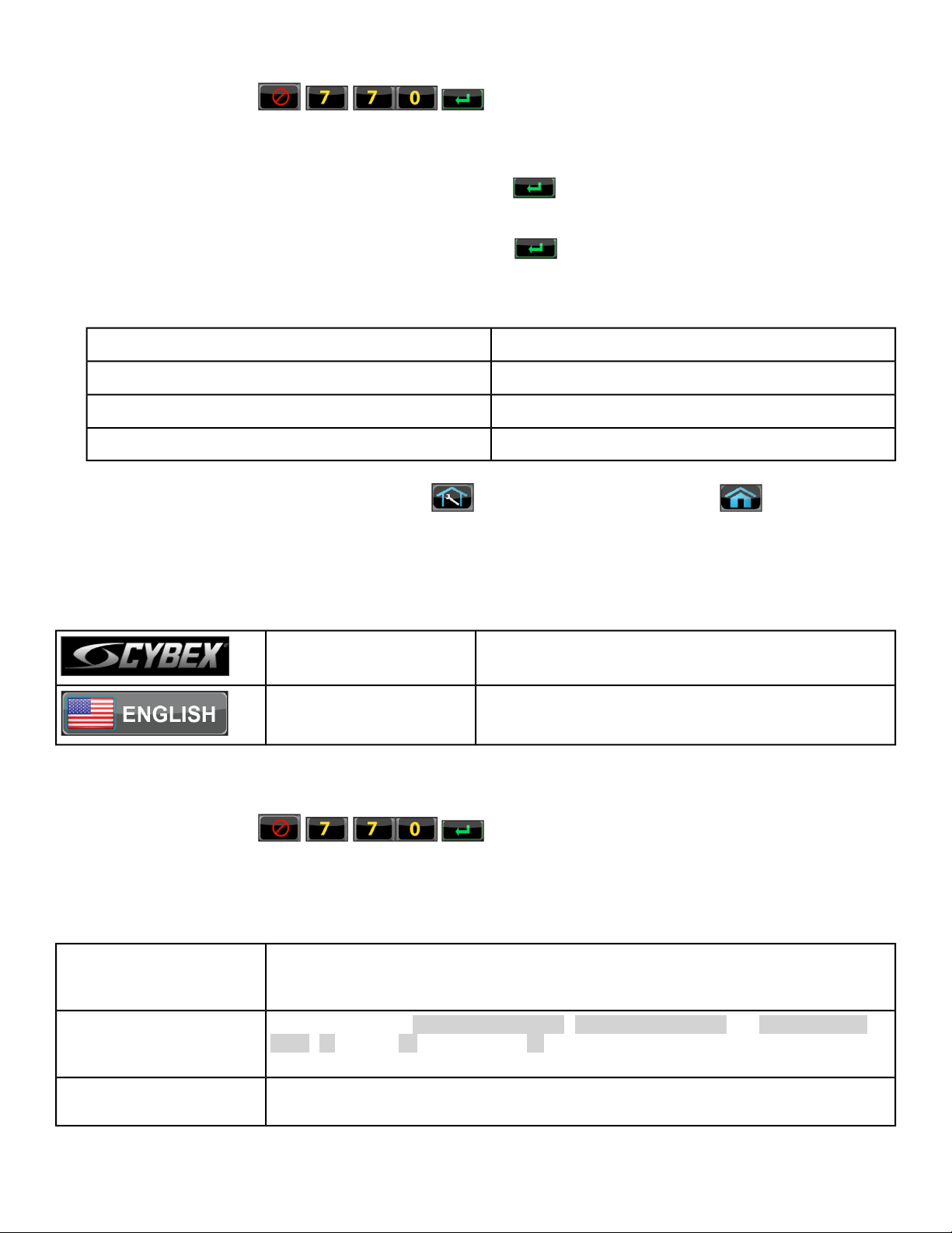
2.
Enter the sequence: .
3. Tap the Setup icon to display the Setup menu.
4. Tap the Time icon to advance to the Set the Time screen.
5.
Adjust the time if needed, then tap the ENTER icon .
6. Tap the Date icon to advance to the Set the Date screen.
7.
Adjust the date if needed, then tap the ENTER icon .
8. Tap the Units icon to select the Set units preference screen.
9. Select the unit preferences from the following options:
Weight UnitsDistance Units
Lbs.Miles
KgKm
Stone
10.
Exit Set Up Mode by tapping the Toolbox icon, then tap the Home icon . The screen will
refresh.
Setup options - LED, E3 View Monitor
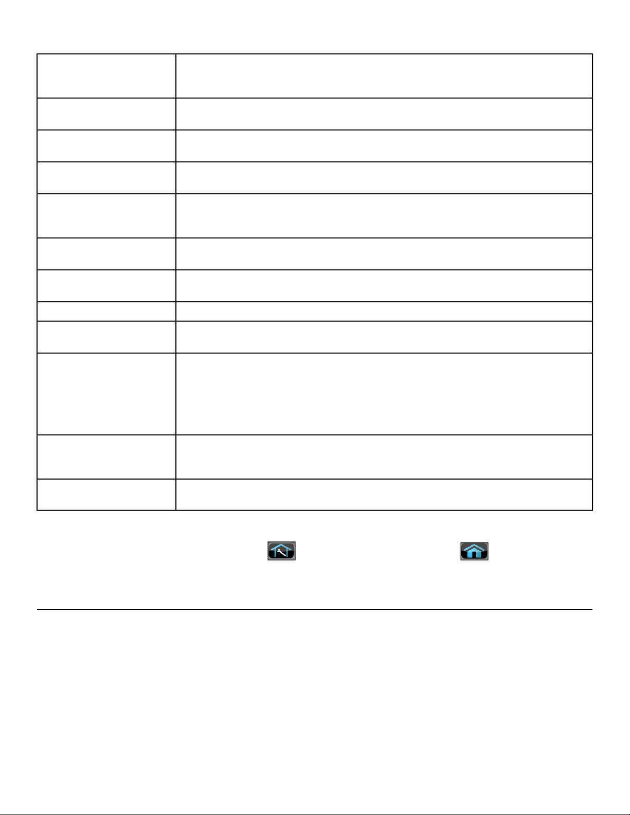
Enter setup options.
Press and hold Cybex logo for 6 seconds to access
Screen Lock and Toolbox.
CYBEX LOGO
Press and hold language logo for 6 seconds to ac-
cess Screen Lock and Toolbox.
LANGUAGE ICON
1. Tap the Access Toolbox icon to display the Access to Toolbox login screen.
2.
Enter the sequence: .
3. Tap the Setup icon to display the Setup menu.
Setup menu
Select Time Display option to On or Off. Add or subtract an hour. Select time
display as AM, PM, or 24 Hour display. Enter time using keypad, press Enter
to save.
Time
Select date style [MM] [DD] [YYYY], [DD] [MM] [YYYY], or [YYYY] [MM]
[DD]. Y - Year, M - Month and D - Day. Enter date using keypad, press
Enter to save.
Date
Select distance units. Miles or Km (Kilometers). Select weight units. Lbs.
(Pounds), Kg. (Kilograms) or Stone (Stones).
Units
Page 44 of 95
Cybex 771A/771AT, 772A/772AT Arc Trainer Part Number 5771-4 K
Select Device Installed. Choices are: No TV, Wireless TV, or C.A.B.
(Console Adapter Box for Broadcast Vision). Contact qualified service tech-
nician for audio visual setup.
TV Input (LED consoles)
Select Device Installed. Choices are: Tuner, STB + Tuner, or STB + HDMI.
Contact qualified service technician for audio visual setup.
TV Source (E3 View
Monitor)
Select No TV, Attached TV, or Wireless TV. Contact qualified service
technician for audio visual setup.
A/V Device (not shown
for E3 View Monitor)
Active when A/V Device is set to Wireless TV. Contact qualified service
technician for audio visual setup.
A/V Config (not shown
for E3 View Monitor)
Active when A/V Device is set to Wireless TV. Contact qualified service
technician for audio visual setup.
FM Radio Presets (not
shown for E3 View Moni-
tor)
Active when A/V Device is set to Embedded TV. Contact qualified service
technician for audio visual setup.
PEM Setup
Set Default and Max workout times. Default choices are 20, 30, or 60 minutes.
Max choices are 20, 30, 60, or OFF.
Workout times
Set Pause time. Choices are OFF, 0:30, 1:00, or 2:00 minutes.Pause
Select console beeper settings. Console Beeper - On or Off. Headphone
Beeper - Off, Some, or All. Default Volume - 1 to 30, default is 10.
Sound
Choose Default Resistance Mode.
Choices are: Arc (default resistance), Constant Power (default power), or
Adaptive Power (default level).
Set default resistance, power, or level.
Quick Start Mode
Select default language to display on CardioTouch screen. Toolbox is only
available in English. Include Optional Languages. Select optional languages
to display on CardioTouch screen. Choices are Include or Off.
Language
Restores all setup variables back to factory defaults. Does not affect Time
or Date.
Restore Factory De-
faults
Exit Set Up Mode
Exit Set Up Mode by tapping the Toolbox icon, then tap the Home icon . The screen will
refresh.
Testing Operation
Use the following instructions to test the full resistance and incline range of the unit:
1. Plug the optional power cord into a power outlet from a grounded circuit.
Coil up the remainder of the power cord and place it out of the way. If you do not have the optional
power supply, skip to step 3.
2. Verify the control panel will illuminate and is in Dormant Mode.
3. Hold the handrails to steady self while stepping into the foot plates.
4. Begin striding.
Page 45 of 95
Cybex 771A/771AT, 772A/772AT Arc Trainer Part Number 5771-4 K

5. Verify lower heart rate cable is not rubbing on handle during operation.
6. Press Quick Start.
7. Run unit through full resistance range.
First press the Resistance + key until unit reaches its highest load (the display will show 100). Then
press the Resistance - key until unit reaches its lowest load (the display will show 0).
When unit reaches the set incline and resistance, the displays will stop flashing and remain steadily
illuminated to indicate the desired settings have been reached.
8. Run unit through full incline range.
First press the Incline key until the unit reaches its highest incline (the display will show 20). Then
press the Incline key until unit reaches its lowest incline (the display will show 0).
Moving parts and fall hazard.
• To avoid serious injury wait until foot plates come to a complete stop
before getting off unit.
• The moving parts cannot be stopped immediately, the unit is not
equipped with a free wheel.
9. Press STOP twice to bring the incline back to its start position, end the workout review, and return
the display to Dormant Mode.
10. Wait until foot plates come to a complete stop before dismounting unit.
Hold handrails to steady self while stepping off unit.
Page 46 of 95
Cybex 771A/771AT, 772A/772AT Arc Trainer Part Number 5771-4 K

Operation
Intended Use
The intended commercial use of this machine is to aid exercise and improve general physical fitness.
Individual human power versus mechanical power
Power difference. The individual human power which is required to carry out
an exercise can be different than the mechanical power displayed.
Terms Used
This section lists some of the common terms and symbols used in this chapter. Other terms and symbols
are listed in this chapter as appropriate.
Any time the unit is controlling resistance and accumulating workout data. Active
Mode begins after tapping Quick Start icon during the initial count-down screen,
Active Mode
after completing the setup for a workout, or by default if the initial count-down
screen times out and enters Quick Start mode.
Display automatically cycles through workout data.Auto-Scan
The CardioTouch Screen is the touch screen located in the handset area.CardioTouch
Screen
A reduction of work load for a short duration allows user to gently reduce heart
rate. Cool Down occurs two minutes prior to completion of the workout-controlled
workout sessions.
Cool Down
Occurs when unit is plugged in and not in use.Dormant Mode
An anatomical representation of the human body with primary muscle groups lit
by multi-color LED’s. The color of the LED displays which muscle groups are tar-
geted and the relative intensity of the exercise.
Muscle Map
Occurs only if the Pause feature is enabled and user selects the STOP key from
Active Mode.
Pause Mode
A collection of workouts with a common theme.Workout Type
This begins by tapping the Quick Start icon. User has full control over the workout
as time counts up.
Quick Start
Review of the accumulated workout data will happen at the end of each workout
session.
Workout Review
Page 47 of 95
Cybex 771A/771AT, 772A/772AT Arc Trainer Part Number 5771-4 K
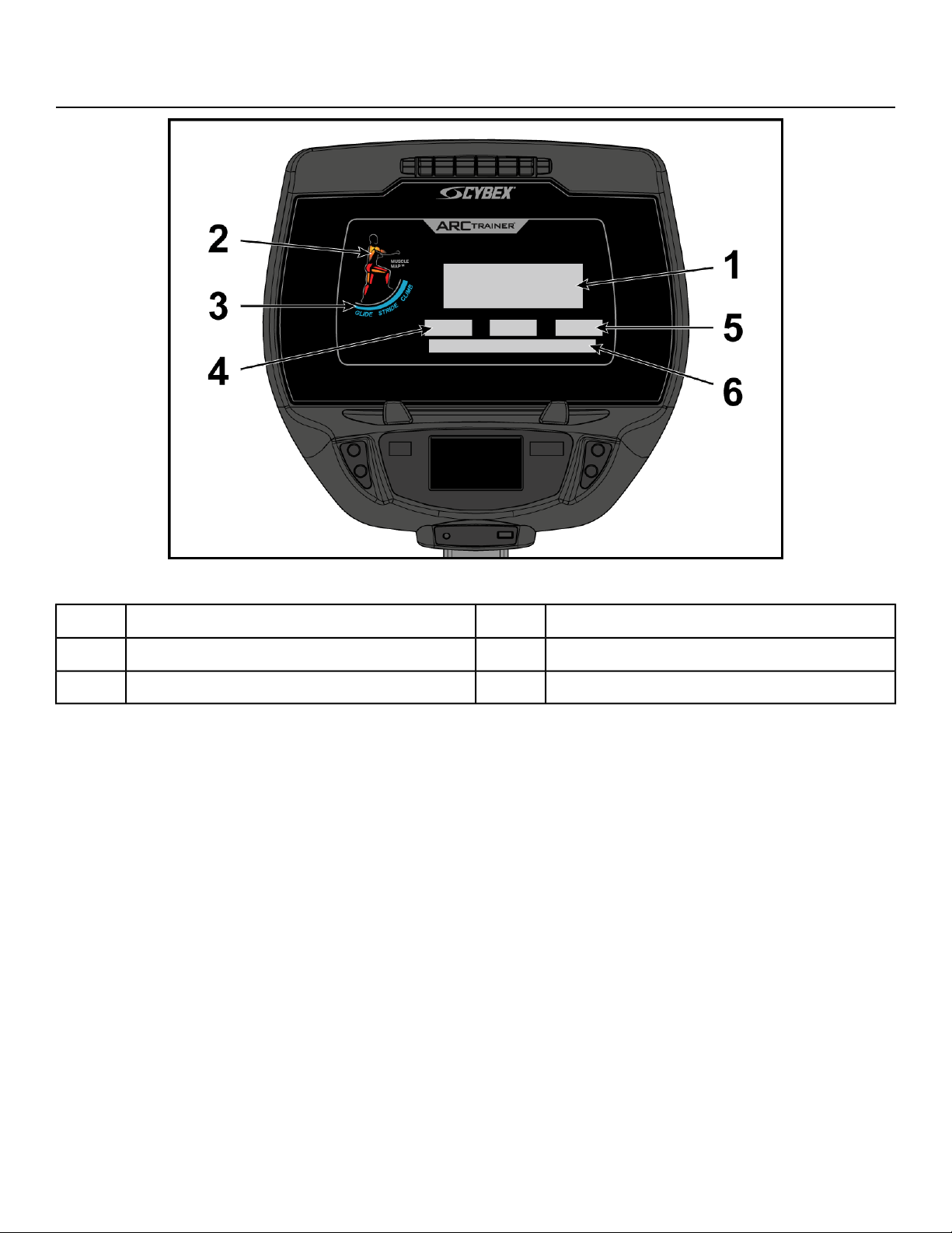
Console Display
LED Display
Data Readouts4Bar Graph1
Heart Rate Indicator5Muscle Map2
Enunciator6Incline Meter3
Page 48 of 95
Cybex 771A/771AT, 772A/772AT Arc Trainer Part Number 5771-4 K
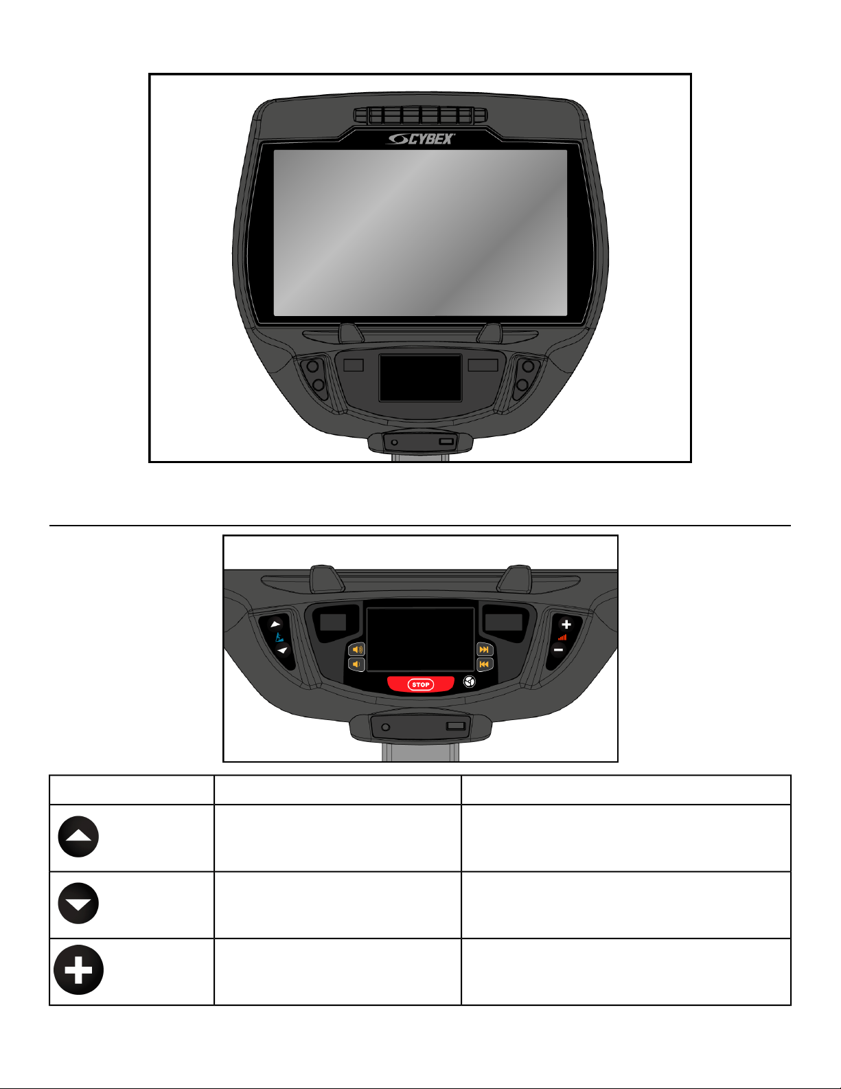
E3 View Monitor
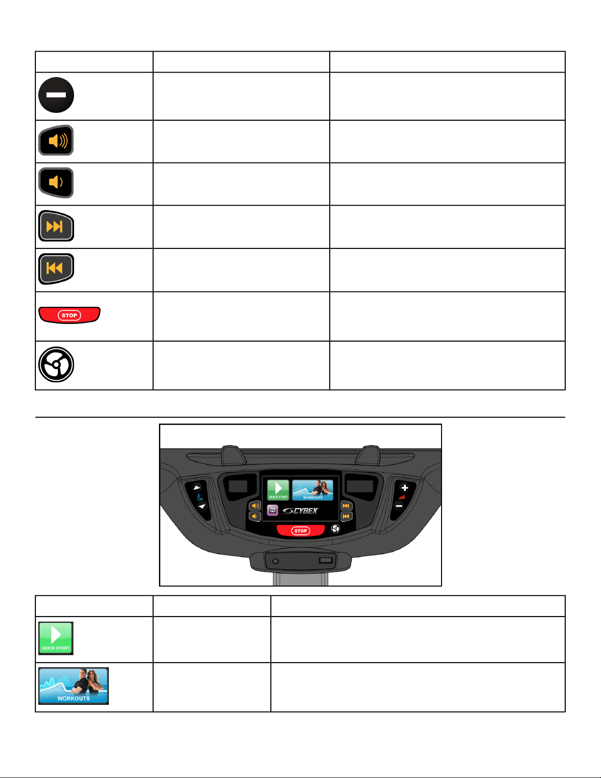
User Control Symbols Used
DescriptionControl NameControl
Adjust Incline up.INCLINE UP
Adjust Incline down.INCLINE DOWN
Adjust Resistance +up.RESISTANCE UP
Page 49 of 95
Cybex 771A/771AT, 772A/772AT Arc Trainer Part Number 5771-4 K
DescriptionControl NameControl
Adjust Resistance -down.RESISTANCE DOWN
Adjust Volume up.VOLUME UP
Adjust Volume down.VOLUME DOWN
A/V - Channel UPCHANNEL UP
A/V - Channel DOWNCHANNEL DOWN
Press STOP once to end the workout session
and start the Workout Review. Press STOP
again to exit to Dormant Mode.
STOP
Default speed is OFF during active mode.
Press the FAN key to control fan speed.
Choices are OFF, LOW and HI.
FAN
CardioTouch Symbols Used
DescriptionIcon NameIcon
Quick Start enters Active Mode at the default settings
with time counting up from 0:00.
Quick Start
Tap Workouts icon to enter workout group selection.WORKOUTS
Page 50 of 95
Cybex 771A/771AT, 772A/772AT Arc Trainer Part Number 5771-4 K
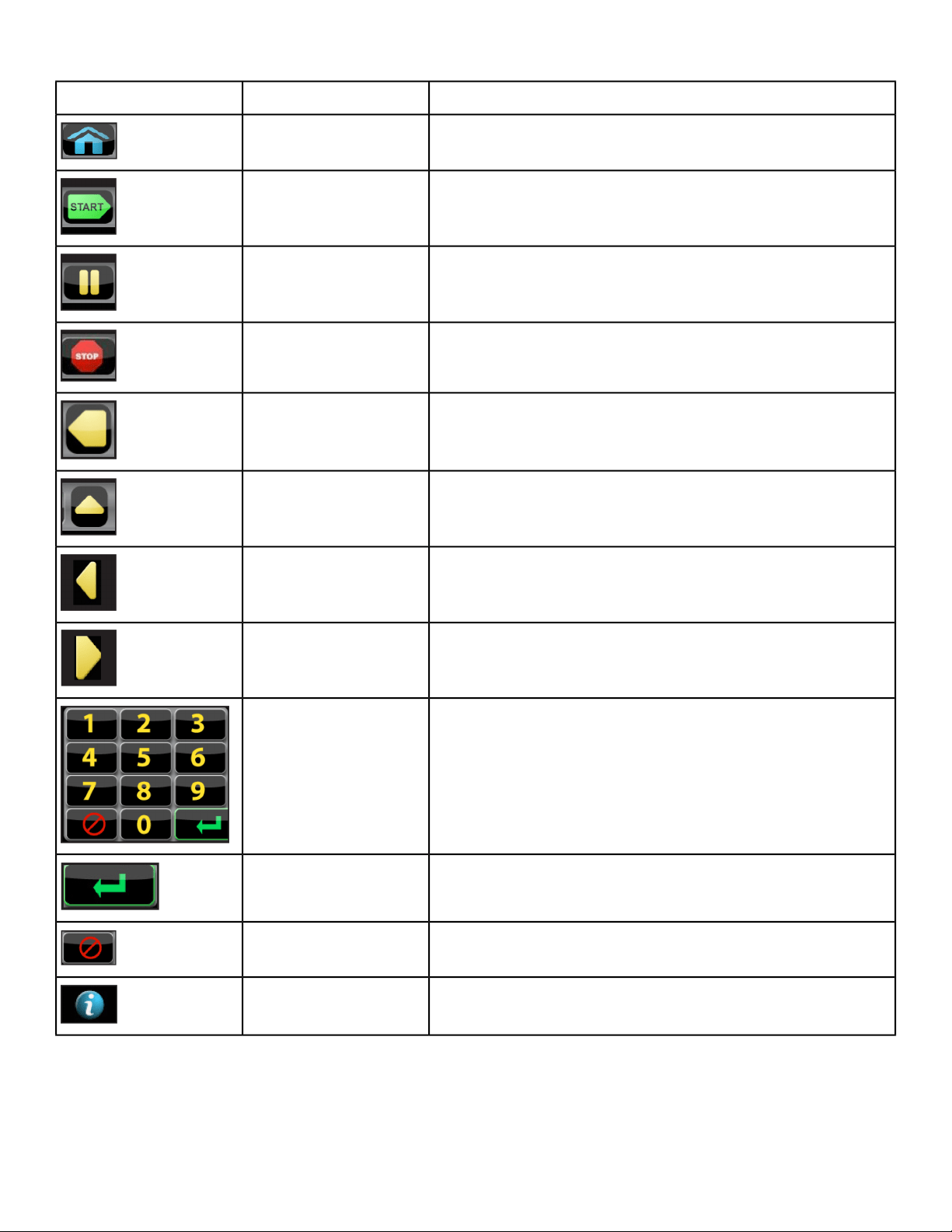
DescriptionIcon NameIcon
Return to opening screen.HOME
Enter Active Mode.START
If pause feature is enabled, pause icon is shown. Press
Pause icon once to enter pause mode.
PAUSE
If pause feature is disabled, stop icon is shown. Press
Stop icon or STOP button once to enter Workout review.
STOP
Return to previous or opening screen.BACK
Go up one level.UP LEVEL
Shift the screen left to view more options.SHIFT LEFT
Shift the screen right to view more options.SHIFT RIGHT
Numeric keypad for entering data.KEYPAD
Accepts the value shown.ENTER
Clear any values selected.CLEAR
Select to provide more information and details.INFO
Page 51 of 95
Cybex 771A/771AT, 772A/772AT Arc Trainer Part Number 5771-4 K
DescriptionIcon NameIcon
Displays current value in the minimum and maximum
range.
SCALE
Press and hold Cybex logo for 6 seconds to access
Screen Lock and Toolbox.
CYBEX LOGO
Press and hold language logo for 6 seconds to access
Screen Lock and Toolbox.
LANGUAGE ICON
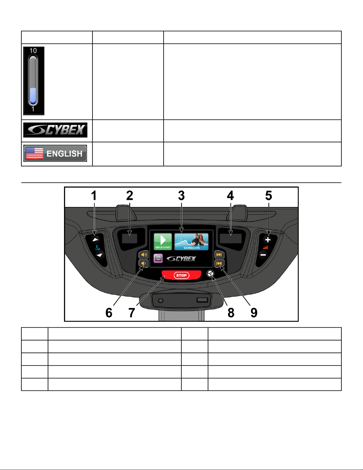
CardioTouch Screen and User Controls
Volume Keys6Incline Keys1
STOP Key7Incline Display2
Fan Key8CardioTouch Screen3
Channel Key9Resistance Display4
Resistance Keys5
Incline and Resistance are shown in the LED displays.Displays
User controls for Incline, Resistance, Volume, STOP, Fan and Channel.Keys
Page 52 of 95
Cybex 771A/771AT, 772A/772AT Arc Trainer Part Number 5771-4 K
Tap the icons to make selections.CardioTouch
screen
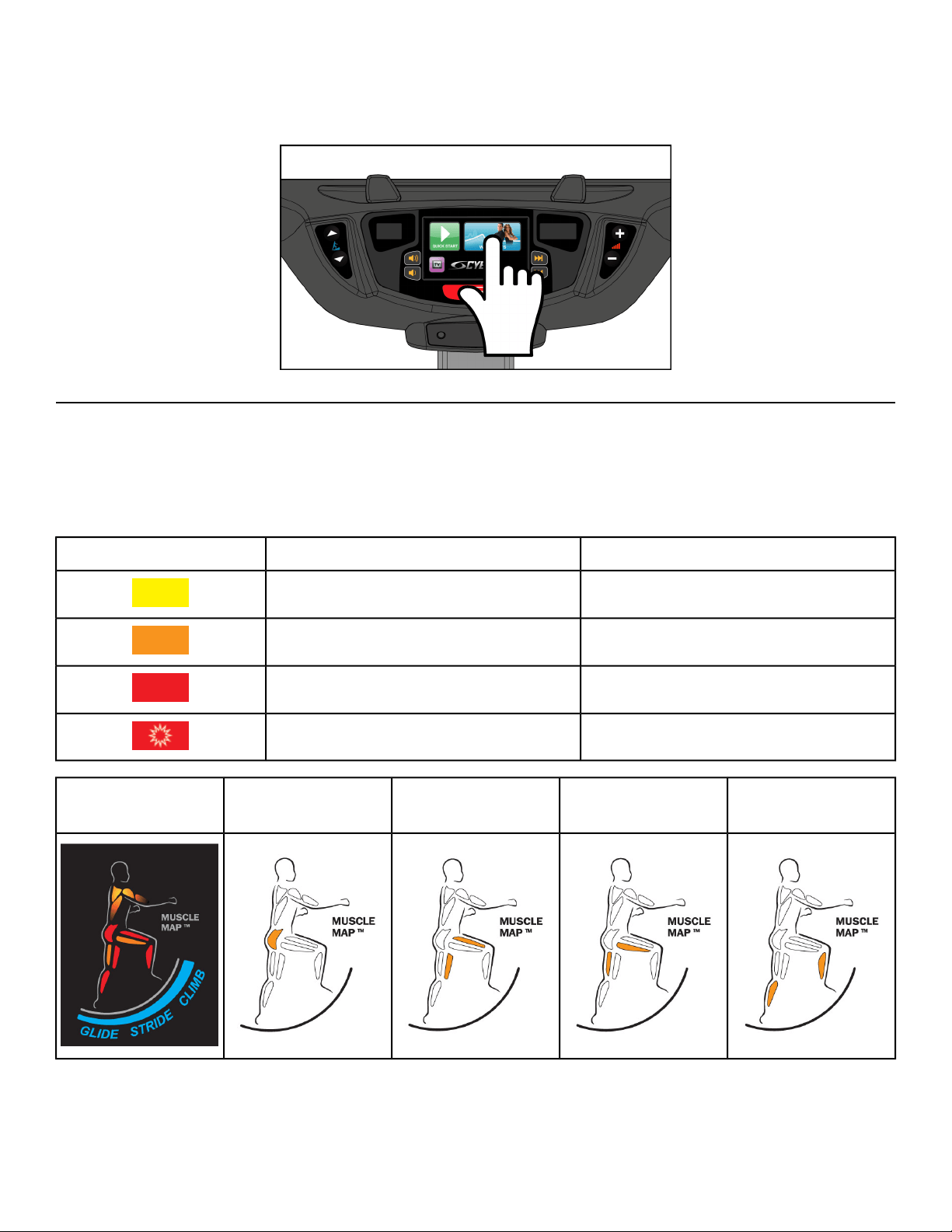
Muscle Map and Incline Meter
An anatomical representation of the human body with primary muscle groups lit
by multi-color LED’s. The color of the LED displays which muscle groups are tar-
geted and the relative intensity of the exercise.
Muscle Map
The LED colors display intensity level.
LevelColorLED
LowYellow
MediumAmber
HighRed
Very highBlinking Red
Calf MuscleHamstring MuscleQuadricep MuscleGlute MuscleMuscle Map and
Incline Meter
An LED meter displaying the incline setting. The meter increase or decreases as
the incline changes.
Incline Meter
Page 53 of 95
Cybex 771A/771AT, 772A/772AT Arc Trainer Part Number 5771-4 K

Mount and Dismount
Mount unit safely
1. Verify foot plates are completely stopped.
2. Grasp handrail and step carefully onto foot plates.
Dismount unit safely
Moving parts and fall hazard.
• To avoid serious injury wait until foot plates come to a complete stop before
getting off unit.
• The moving parts cannot be stopped immediately, the unit is not equipped
with a free wheel.
1. Grasp handrails for support.
2. Stop striding.
3. Wait until foot plates come to a complete stop.
4. Continue to hold handrails while carefully stepping off unit.
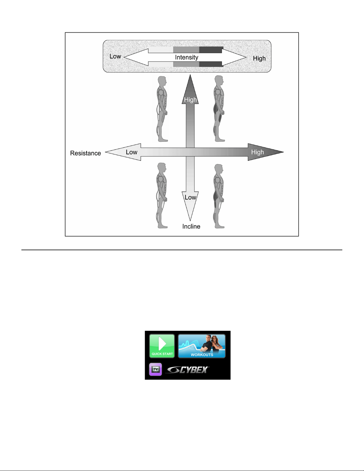
Range of Motion
The incline is adjustable up or down in the shape of an arc. The lowest setting of 0 equates to an arc
of 12 degrees, where the highest setting of 20 equates to an arc of 34.5 degrees. There is no difference
in muscles used between different incline positions. Differences exist in the intensity of muscle activity.
Page 54 of 95
Cybex 771A/771AT, 772A/772AT Arc Trainer Part Number 5771-4 K
Quick Operation Guide
Maximum user weight is 400 lbs. (181 kg).
The following is a quick overview of the operation of the unit.
1. Verify foot plates are completely stopped.
2. Grasp handrail and step carefully onto foot plates.
Begin striding.
3. Tap Quick Start on the CardioTouch screen.
The CardioTouch screen will display “Starting” and enter Active Mode.
4. Begin striding.
5. Press the Incline ▲▼ keys to change the incline at any time.
The left display will show incline.
6. Press the Resistance + – keys to change the resistance at any time.
The right display will show the current resistance.
Page 55 of 95
Cybex 771A/771AT, 772A/772AT Arc Trainer Part Number 5771-4 K
7. Press the STOP key at any time to pause.
Detailed Operation Guide
Maximum user weight is 400 lbs. (181 kg).
1. Plug the optional power cord and E3 View Monitor power cord (E3 View Monitor units only) into a
power outlet from a grounded circuit.
Coil up the remainder of the power cord and place it out of the way. The control panel will light up
and be in the Dormant Mode.
2. Verify foot plates are completely stopped.
3. Grasp handrail and step carefully onto foot plates.
Begin striding.
4. Select Quick Start or WORKOUTS.
To select a workout category, tap one of the workout category icons from the workout options screen.
To select a workout, tap one of the workout icons from the workouts screen.
Upon entering a workout the display will guide you through the appropriate settings. This is referred
to as Workout Setup Mode. If the Start icon is tapped now, all defaults for that workout will be
accepted. After 10 seconds, if no key has been pressed, the first default will be accepted. After
another 10 seconds the second default will be accepted and so on until the last default.
For the most accurate resistance and calorie count, you must set your correct weight before beginning
your workout (including clothing).
When selecting a workout you must tap the Enter icon after each adjustment of Time, Level or
Weight.
Page 56 of 95
Cybex 771A/771AT, 772A/772AT Arc Trainer Part Number 5771-4 K
5. Tap the Start icon.
The CardioTouch screen will display Starting and enter Active Mode.
6. Begin striding.
7. Observe the control panel.
The top center Bar Graph display shows a graphical representation of the relative incline changes,
and if in a workout, will show the relative intensity changes that are coming up. The Data Readouts
will start showing the workout data such as Distance, Calories, Heart rate (if available), METs and
Pace (Minutes per Mile or Minutes per Km). The data displays will start by automatically shifting
every 5 seconds.
Heart rate will be displayed in lieu of METs if a valid heart rate is available from a wireless chest
strap (not included) or by holding the contact heart rate grips.
When you adjust incline in a workout, the change will affect only the current segment. The workout
control will resume starting with the next segment. To increase or decrease overall intensity, adjust
the speed and/or the workout level.
8. Press the Incline ▲▼ keys to change the incline at any time.
The left display will show incline.
9. Press the Resistance + – keys to change the resistance at any time.
The right display will show the current resistance.
10. Press the STOP key at any time to pause.
a)
If pause feature is enabled, pause icon is shown.
Press pause icon or STOP button once to enter pause mode.
b)
If pause feature is disabled, stop icon is shown.
Press stop icon or STOP button once to enter Workout review. Workout review is displayed
and the incline returns to 6%.
When a workout is complete the unit begins a countdown, 3...2...1 and sounds a tone for each
count. Workout Review is displayed for the preset time or until you press the Home key. The
unit returns to Dormant Mode when using the optional AC adapter.
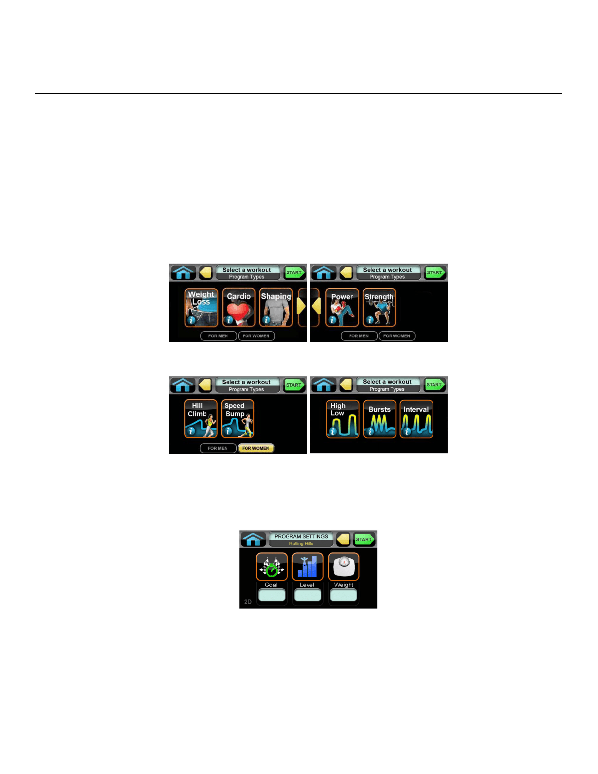
Workout Selection
You may choose from Quick Start or Workouts. Speed is never predetermined. Change speed by
changing stride.
Quick Start
Press Quick Start. Control incline and resistance
Page 57 of 95
Cybex 771A/771AT, 772A/772AT Arc Trainer Part Number 5771-4 K

Workouts
SettingsLevelsFor WomenFor Men
Weight Loss
Select time, level, and weight.
10Hill ClimbHill Climb
Select time, level, and weight.10Speed BumpSpeed Bump
Strength
Select time, level, and weight.10High LowHigh Low
Select time, level, and weight.10BurstsBursts
Select time, level, and weight.10IntervalInterval
ShapingFitness
Select time, level, and weight.10Total LegTotal Leg
Select time, level, and weight.10Glute CampTarget: Hip
Cardio
Select time, level, and weight.10Hill IntervalHill Interval
Select time, level, and weight.10WaveWave
Select time, level, and weight.10IntervalInterval
Select time, age, target heart rate, and weight.N/A
Heart Rate Con-
trol
Heart Rate Con-
trol
Power
Select time, level, and weight.10Constant PowerConstant Power
Select time, level, and weight.10Adaptive PowerAdaptive Power
See Appendix for Workout Overviews
Data Readouts - LED display
As you exercise, the unit keeps track of the following data:
Your current heart rate. Heart rate will appear when a signal is introduced. Use
the hand grips for Contact Heart rate or wear a Polar
®
compatible heart rate chest
strap.
BPM (Beats Per
Minute)
The total accumulated calories burned during your workout. Your weight must be
correctly set before beginning your workout for this measurement to be most ac-
curate.
Calories
Calculation of present workload's energy exertion in Calories per Hour.Calories Per Hour
The total accumulated distance during workout. Depending on the defaults chosen,
this measurement will show in English (miles) or Metric (kilometers). The unit uses
Distance
Page 58 of 95
Cybex 771A/771AT, 772A/772AT Arc Trainer Part Number 5771-4 K
a fixed 24” (61 cm) stroke, giving a travel distance of 48” (122 cm) per revolution.
Distance = Strides per Minute × 24” (61 cm) × Time
Relates to the user's energy expenditure. A MET is a basic unit of measurement
that is used to compare relative work between individuals and activities. 'One MET'
Metabolic Equiva-
lent (MET)
is the amount of oxygen consumed at rest. For example, two MET would be twice
that amount. If an individual were working at four MET he/she would be consuming
oxygen at a rate equal to four times their resting consumption. MET can be used
to compare walking on a grade with running or even to cycling and other activities.
The average number of strides per minute at current speed.SPM (Strides per
Minute)
Present workload energy exertion.Watt
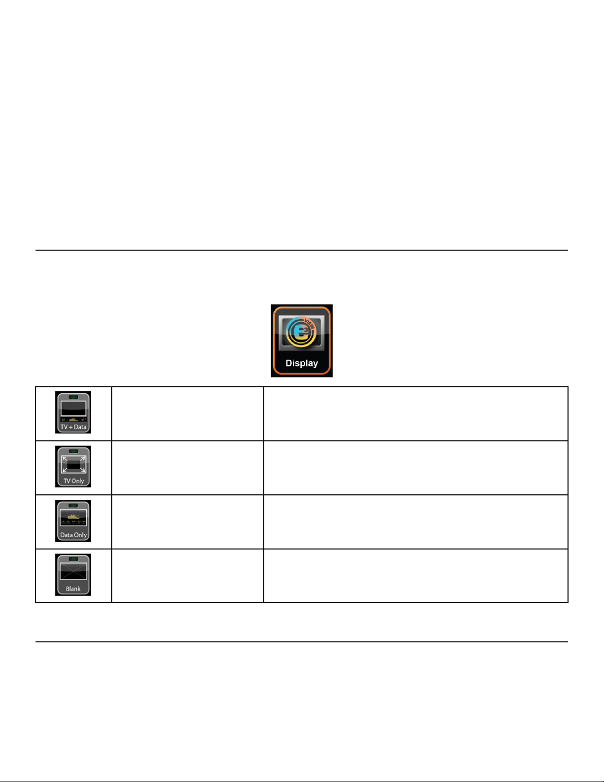
E3 View Monitor Screen Options
During operation four E3 View Monitor screen options are available.
Press E3 View Monitor icon to change screens.
Display video with data at bottom of screenTV + Data
Display video onlyTV Only
Display data onlyData Only
Screen is blank, video and data are not displayedBlank
Heart Rate Indicator
Lightly hold hand grips on the handlebar ensuring that hands are clean and contact
both the front and back sensors of each grip. A heart rate will display in typically
30 seconds or less.
Contact Heart
Rate
Page 59 of 95
Cybex 771A/771AT, 772A/772AT Arc Trainer Part Number 5771-4 K
Factors that interfere with heart rate signal:
• hand lotions
• oils or body powder
• excessive dirt
• excessive movement
• body composition
• hydration
• too loose grip
• too tight grip
• resting or leaning on grips
To use this feature, a 5 KHz Polar
®
compatible heart rate transmitter belt (not in-
cluded) must be worn.
Wireless Heart
Rate
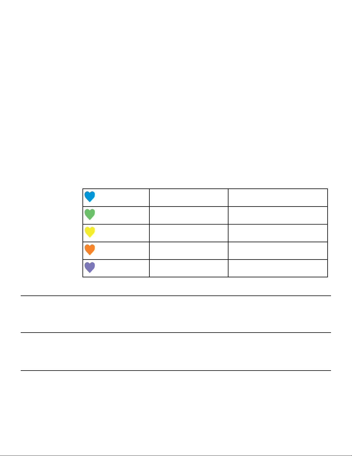
Once the actual heart rate is determined, the LED is blinking to the displayed BPM
and the Heart LED lights up. The color of the light represents a scale of low to
high target heart rate.
0 - 69 BPMBlue
70 - 93 BPMGreen
94 - 119 BPMYellow
120 - 169Dark Orange
170 and higherMagenta
Fan Control
The fan defaults to the "OFF" setting. The user can change to "Fan Low", "Fan High", or "Fan Off" setting
by pressing the appropriate control key.
How power input versus displayed value is calculated
Total power, as displayed in Watts on the console, is calculated from the measured speed of the Eddy
Current Brake Flywheel and the measured current powering the Eddy Current Brake.
Testing Parameters
Displayed power (Wattage) and speed (Strides Per Minute), were found to meet class A accuracy when
compared with measured power and speed, with adjustable braking positioned in its maximum position,
at the following accuracy test points:
• 25 W, 37 SPM
• 50 W, 52 SPM
Page 60 of 95
Cybex 771A/771AT, 772A/772AT Arc Trainer Part Number 5771-4 K

• 100 W, 72 SPM
• 150 W, 86 SPM
• 175 W, 92 SPM
• 200 W, 97 SPM
Page 61 of 95
Cybex 771A/771AT, 772A/772AT Arc Trainer Part Number 5771-4 K

Maintenance
All preventive maintenance activities must be performed on a regular basis. Performing routine preventive
maintenance actions can aid in providing safe, trouble-free operation of all Cybex equipment.
Cybex is not responsible for performing regular inspection and maintenance actions for your machines.
Instruct all personnel in equipment inspection and maintenance actions and also in accident reporting
and recording. Cybex representatives are available to answer any questions that you may have.
Warnings
Read all warnings in this chapter.
For maintenance, service and repair:
• Must be performed by trained service personnel only
• Use only Cybex replacement parts
• Unplug unit before working on it
• Keep water and liquids away from electrical parts.
Electrocution hazard. To avoid death or serious injury unplug unit when not
in use or when performing maintenance.
Equipment hazard. To avoid serious injury or death replace worn or damaged
components immediately and keep the equipment out of use until repair is
completed.
Clean Unit
Shock and electrocution hazard.
• Unplug unit and let sit 10 minutes before cleaning or performing
maintenance.
• Electrical charge can remain in unit after unplugging.
• Keep water and liquids away from electrical parts.
Tools Required
• Cleaning solution
• Rubbing alcohol
• Clean cloth
• Vacuum
After Each Use
Wipe up any liquid spills immediately. After each workout, use a cloth to wipe up any remaining
perspiration from the handrails and painted surfaces.
Be careful not to spill or get excessive moisture between the edge of the display panel and the console,
as this might create an electrical hazard or cause failure of the electronics.
Page 62 of 95
Cybex 771A/771AT, 772A/772AT Arc Trainer Part Number 5771-4 K

As Needed
Vacuum any dust or dirt that might accumulate under or around the unit. Cleaning this area should be
done as often as indicated in the Service Schedule.
Clean Console
Do not spray cleaning solution directly on the console. Direct spraying could
cause damage to the electronics and may void the warranty.
• Spray a mild cleaning agent on a clean cloth.
• Clean the console, accessory tray, and cup holder with a damp cloth.
Clean Base
• Spray a mild cleaning agent on a clean cloth.
• Clean the base of the unit with a damp cloth.
Contact Heart Rate Grips
Clean the grips using a cloth dampened with a cleaning solution containing rubbing alcohol.
Contaminants, such as hand lotions, oils or body powder, may come off on the contact heart rate grips.
These can reduce sensitivity and interfere with the heart rate signal. It is recommended that the user
have clean hands when using the contact heart rate.
CardioTouch Screen
While in Dormant Mode press the Cybex logo icon to access the Lock and Toolbox options. Press the
Lock screen for cleaning icon to lock the screen for 10 seconds. The CardioTouch screen will stay
locked for 10 seconds to prevent any key presses from being processed.
• Clean with a dust free cloth. For further cleaning, use a soft cloth or paper towel dampened with
water. To avoid damage to the surface of the monitor, do not use abrasive or chemical cleaning
agents.
• Disinfecting: to avoid damage to the surface, test a small portion of the monitor’s cabinet with any
disinfectant to verify that the disinfectant will not discolor or soften the enclosure.
Page 63 of 95
Cybex 771A/771AT, 772A/772AT Arc Trainer Part Number 5771-4 K

Drive Belts
Remove front access cover
1. Remove screws securing front access cover using a Phillips screwdriver.
Qty.Description
4Screw1
1Front access cover2
2. Remove access cover.
Burn hazard. Do not touch flywheel until cool.
Inspect drive belts
There are two drive belts that may become loose, worn or cracked.
Unless the belts have been removed and not replaced properly, it is unlikely the belts will come loose
or need to be re-tensioned.
Qty.Description
1Primary drive belt1
1Secondary drive belt2
If a belt has cracks or appears worn, it must be replaced immediately by a qualified service technician.
Primary Belt
The wider of the two belts. It has grooves that keep it aligned on the large upper pulley.
Page 64 of 95
Cybex 771A/771AT, 772A/772AT Arc Trainer Part Number 5771-4 K

Secondary Belt
The narrower of the two belts. It has grooves that keep it aligned on the flywheel's drive pulley.
Install access cover
Do not over tighten screws.
1.
Replace and tighten the two upper screws using a Phillips screwdriver.
2.
Replace and tighten the two lower screws using a Phillips screwdriver.
3. Test unit for proper operation.
Rechargeable Battery
The unit is designed with a 12 volt Lead-Acid rechargeable battery. The battery will recharge during
regular operation of unit or when the optional power adapter is plugged in.
The display will indicate dashes in the incline display if the battery fails to provide enough energy. The
unit will still function normally other than the disabling of the incline feature.
If the battery is completely discharged, the workout review will also be truncated if the user is not striding
during the time period. See Customer Service for contact information to replace the battery or purchase
the optional AC adapter kit.
Battery replacement must be performed only by qualified technician.
Remove battery and dispose of safely before unit disposal.
E3 View Monitor
Cleaning
• Clean with a dust free cloth. For further cleaning, use a soft cloth or paper towel dampened with
water. To avoid damage to the surface of the monitor, do not use abrasive or chemical cleaning
agents.
• Disinfecting: to avoid damage to the surface, test a small portion of the monitor’s cabinet with any
disinfectant to verify that the disinfectant will not discolor or soften the enclosure.
Storage or Long Non-Use Periods
When not using product for an extended period of time the product should be disconnected from the
Power Supply, TV/Cable Signal Feed, and any Peripheral Devices.
Pixels
Very small red, blue, white or green spots may be visible or may appear on the screen. This is a
characteristic of liquid crystal display panels and is not considered a defect for replacement. The liquid
crystal panel is built with very high precision technology giving fine picture details. Occasionally, a few
non-active pixels may appear on the screen as a fixed point. This does not affect the performance of
monitor or merit a warranty claim.
Page 65 of 95
Cybex 771A/771AT, 772A/772AT Arc Trainer Part Number 5771-4 K
Maintenance
• It is very important to have the unit regularly examined by a qualified technician to ensure the product
is fit for use.
• If the unit malfunctions, please refer to a qualified technician for repair or replacement of defective
parts immediately. Do not attempt to use the monitor until it has been inspected and repaired by a
qualified technician.
• For inspection, installation and servicing, please consult qualified technician.
• Failure to use a manufacturer approved repair technician may void any warranty claims.
Service Schedule
All maintenance activities shall be performed by qualified personnel. Failure to do so could result in
serious injury.
This is the minimum recommended service.
Determine distance
Press and hold Cybex logo for 6 seconds to access
Screen Lock and Toolbox.
CYBEX LOGO
Press and hold language logo for 6 seconds to ac-
cess Screen Lock and Toolbox.
LANGUAGE ICON
1. Tap the Access Toolbox icon to display the Access to Toolbox login screen.
2.
Enter the sequence: .
3. Press the Statistics icon to access the Recorded Statistics screen.
4. Locate and tap the icon for Arc Trainer Totals.
5. Record Distance.
6.
Exit Set Up Mode by tapping the Toolbox icon, then tap the Home icon . The screen will
refresh.
First 500 Miles (800 KM)
Follow this procedure to ensure the belts are tensioned properly and in good condition.
1.
Remove access cover. (See previous procedure Remove Access Cover)
2. Pull down and roll each belt to examine the condition. If a belt has cracks or appears worn, it must
be replaced immediately by a qualified service technician.
3.
Attach access cover. (See previous procedure Attach Access Cover)
Every 5000 Miles (8000 KM)
Check drive belts for tension and wear. (See procedure First 500 Miles)
Page 66 of 95
Cybex 771A/771AT, 772A/772AT Arc Trainer Part Number 5771-4 K
Move unit and vacuum underneath. Lift the rear of unit and roll it back from its present position. Vacuum
underneath and return unit to normal position.
Clean inside unit.
1.
Remove access cover. (See previous procedure Remove Access Cover)
2. Using a vacuum cleaner attachment or hand vacuum, clean the exposed components.
3. Remove dirt and debris from internal components.
4. Using a dry cloth, wipe all exposed areas.
5.
Attach access cover. (See procedure Attach Access Cover)
Every 20,000 Miles (32000 KM)
Contact qualified service technician to check elevation assembly, replace any worn parts and lubricate
elevation bushings.
Statistics
The Statistics screen allows tracking of equipment usage.
Press and hold Cybex logo for 6 seconds to access
Screen Lock and Toolbox.
CYBEX LOGO
Press and hold language logo for 6 seconds to ac-
cess Screen Lock and Toolbox.
LANGUAGE ICON
1. Tap the Access Toolbox icon to display the Access to Toolbox login screen.
2.
Enter the sequence: .
3. Press the Statisticsicon to access the Recorded Statisticsscreen.
4. Locate and tap the icon for Arc Trainer Totals.
DisplayStatistics Menu
Total accumulated miles or KMDistance
Total time in active modeHours
Total number of workout sessionsStarts
Number of incline moves in 1% incrementsMoves
Total number of hours the console has been onOn Time
Total number of minutes the battery has been usedOn Battery
Number of days since install dateDays in svc
Page 67 of 95
Cybex 771A/771AT, 772A/772AT Arc Trainer Part Number 5771-4 K

5.
Exit Set Up Mode by tapping the Toolbox icon, then tap the Home icon . The screen will
refresh.
Page 68 of 95
Cybex 771A/771AT, 772A/772AT Arc Trainer Part Number 5771-4 K

Customer Service
Product Registration
To register product do the following:.
1.
Visit www.cybexintl.com.
2. Locate Product Registration in the Support section.
3. Fill out form completely.
4. Click the Submit button to register product.
Contacting Service
Hours of phone service are Monday through Friday from 8:30 a.m. to 6:00 p.m. Eastern Standard Time.
For Cybex customers living in the USA, contact Cybex Customer Service at 888-462-9239.
For Cybex customers living outside the USA, contact Cybex Customer Service at 508-533-4300 or fax
Find information on the web at www.cybexintl.com.
To contact us online go to www.cybexintl.com.
Ordering Parts
To order parts online go to www.cybexintl.com.
To speak with a customer service representative, call 888-462-9239 (for customers living within the
USA) or 508-533-4300 (for customers outside the USA).
The following information located on the serial number decal will assist our Cybex representatives in
serving you.
• Unit Serial Number, Product Name and Model Number
• Part Description and Part Number if you have it. All parts can be found on the web at
www.cybexintl.com
• Shipping Address
• Contact Name
• Include a description of the problem.
In addition to your shipping address and contact name, your account number is helpful but not required.
You may also fax orders to 508-533-5183.
Page 69 of 95
Cybex 771A/771AT, 772A/772AT Arc Trainer Part Number 5771-4 K

Return Material Authorization (RMA)
The Return Material Authorization (RMA) system is used when returning material for placement, repair
or credit. The system assures that returned materials are properly handled and analyzed. Follow the
following procedures carefully.
Contact your authorized Cybex dealer on all warranty-related matters. Your local Cybex dealer will
request a RMA from Cybex, if applicable. Under no circumstances will defective parts or equipment be
accepted by Cybex without proper RMA and an Automated Return Service (ARS) label.
Please contact Cybex Customer Service for the return of any item that is defective.
Provide the technician with a detailed description of the problem you are having or the defect in the item
you wish to return. Provide the model and serial number of your Cybex equipment.
At Cybex’s discretion, the technician may request that you return the problem part(s) to Cybex for
evaluation and repair or replacement. The technician will assign you a RMA number and will send you
an ARS label. The ARS label and the RMA numbers must be clearly displayed on the outside of the
package that contains the item(s) to be returned. Include the description of the problem, the serial
number of the equipment and the name and address of the owner in the package along with the part(s).
Merchandise returned without an RMA number on the outside of the package or shipments sent COD
will not be accepted by the Cybex receiving department.
Damaged Parts
Materials damaged in shipment should not be returned for credit. Shipping damages are the responsibility
of the carrier (UPS, Federal Express, trucking companies, etc.)
Apparent Damage
Upon receipt of your shipment, check all items carefully. Any damage seen with a visual check must be
noted on the freight bill and signed by the carrier’s agent. Failure to do so will result in the carriers refusal
to honor your damage claim. The carrier will provide you with the required forms for filing such claims.
Concealed Damage
Damage not seen with a visual check upon receipt of a shipment but notices later must be reported to
the carrier as soon as possible. Upon discovery of the damage, a written or phone request to the carrier
asking them to perform an inspection of the materials must be made within ten days of the delivery date.
Keep all shipping containers and packing materials as they will be needed in the inspection process.
The carrier will provide you with an inspection report and the necessary forms for filing a concealed
damage claim. Concealed damage claim is the carrier’s responsibility.
Page 70 of 95
Cybex 771A/771AT, 772A/772AT Arc Trainer Part Number 5771-4 K
Appendix - Workout Overviews
Weight Loss - Hill Climb
A gentle calorie burner with steady work increases over 3 minutes followed by a 1 minute rest.
:30:30:30:301:001:001:001:00:30:30:30:30Time
Cool DownCore SegmentsWarm UpIncline
151515151550454035353030Resistance10
666661816141212106Incline10
8080808080110110110110110110110
Target
Pace
10
151515151545403530302525Resistance9
66666161412101086Incline9
8080808080110110110110110110110
Target
Pace
9
101015151540353025252020Resistance8
666661412108866Incline8
8080808080110110110110110110110
Target
Pace
8
101010101035302520201515Resistance7
66664121086646Incline7
8080808080110110110110110110110
Target
Pace
7
101010101030252015151010Resistance6
6666410864426Incline6
8080808080110110110110110110110
Target
Pace
6
5510101025201510101010Resistance5
Page 71 of 95
Cybex 771A/771AT, 772A/772AT Arc Trainer Part Number 5771-4 K

:30:30:30:301:001:001:001:00:30:30:30:30Time
Cool DownCore SegmentsWarm UpIncline
666628642226Incline5
8080808080110110110110110110110
Target
Pace
5
555552015105555Resistance4
666626422226Incline4
8080808080110110110110110110110
Target
Pace
4
555551515105555Resistance3
666624422226Incline3
8080808080110110110110110110110
Target
Pace
3
55555151055555Resistance2
666604200006Incline2
8080808080110110110110110110110
Target
Pace
2
55555101055555Resistance1
666602200006Incline1
8080808080110110110110110110110
Target
Pace
1
Page 72 of 95
Cybex 771A/771AT, 772A/772AT Arc Trainer Part Number 5771-4 K
Weight Loss - Speed Bump
A relatively steady workload includes a high output bump for increased energy expenditure.
:30:30:30:301:001:001:001:001:001:00:30:30:30:30Time
Cool DownCore SegmentsWarm UpLevel
2020202025252555353530302525
Resis-
tance
10
666622210666646Incline10
100100100100100110110130110110110110110110
Target
Pace
10
1515151520202050303025252020
Resis-
tance
9
666622210666646Incline9
100100100100100110110130110110110110110110
Target
Pace
9
1515151520202050303025252020
Resis-
tance
8
66662228666646Incline8
100100100100100110110130110110110110110110
Target
Pace
8
1515151520202050303025252020
Resis-
tance
7
66662228666646Incline7
100100100100100110110120110110110110110110
Target
Pace
7
1010101020202045252520201515
Resis-
tance
6
66662228666646Incline6
8080100100100110110120110110110110110110
Target
Pace
6
Page 73 of 95
Cybex 771A/771AT, 772A/772AT Arc Trainer Part Number 5771-4 K

:30:30:30:301:001:001:001:001:001:00:30:30:30:30Time
Cool DownCore SegmentsWarm UpLevel
1010101020202040252520201515
Resis-
tance
5
66662226444426Incline5
8080100100100110110120110110110110110110
Target
Pace
5
1010101015151540202015151010
Resis-
tance
4
66662226222206Incline4
8080808080100100110100100100100100100
Target
Pace
4
1010101015151535202015151010
Resis-
tance
3
66660224200006Incline3
8080808080100100110100100100100100100
Target
Pace
3
5555151515301515101055
Resis-
tance
2
66660224200006Incline2
8080808080100100110100100100100100100
Target
Pace
2
5555151515301515101055
Resis-
tance
1
66660004000006Incline1
8080808080100100100100100100100100100
Target
Pace
1
Page 74 of 95
Cybex 771A/771AT, 772A/772AT Arc Trainer Part Number 5771-4 K
Strength - High Low
Two levels of intensity and duration help develop muscular strength and endurance.
:30:30:30:301:001:001:001:001:001:001:00:30:30:30:30Time
Cool DownCore SegmentsWarm UpLevel
2020253030301003030656565656060
Resis-
tance
10
6666161620202020201816146Incline10
100100100100110110110110110110110110110110110
Target
Pace
10
202020252525952525606060605555
Resis-
tance
9
6666141418181818181614126Incline9
100100100100110110110110110110110110110110110
Target
Pace
9
202020252525902525555555555050
Resis-
tance
8
6666121216161616161412106Incline8
100100100100110110110110110110110110110110110
Target
Pace
8
151520202020752020505050504545
Resis-
tance
7
6666121216161616161412106Incline7
100100100100110110110110110110110110110110110
Target
Pace
7
151520202020652020454545454040
Resis-
tance
6
666610101414141414121086Incline6
100100100100110110110110110110110110110110110
Target
Pace
6
Page 75 of 95
Cybex 771A/771AT, 772A/772AT Arc Trainer Part Number 5771-4 K

:30:30:30:301:001:001:001:001:001:001:00:30:30:30:30Time
Cool DownCore SegmentsWarm UpLevel
101015151515551515404040403535
Resis-
tance
5
666610101414141414121086Incline5
100100100100110110110110110110110110110110110
Target
Pace
5
101015151515451515353535353030
Resis-
tance
4
666688121212121210866Incline4
100100100100110110110110110110110110110110110
Target
Pace
4
101010101010351010303030302525
Resis-
tance
3
666688121212121210866Incline3
100100100100110110110110110110110110110110110
Target
Pace
3
101010101010301010252525252020
Resis-
tance
2
66666610101010108646Incline2
100100100100110110110110110110110110110110110
Target
Pace
2
101010101010251010202020201515
Resis-
tance
1
66666610101010108646Incline1
100100100100110110110110110110110110110110110
Target
Pace
1
Page 76 of 95
Cybex 771A/771AT, 772A/772AT Arc Trainer Part Number 5771-4 K
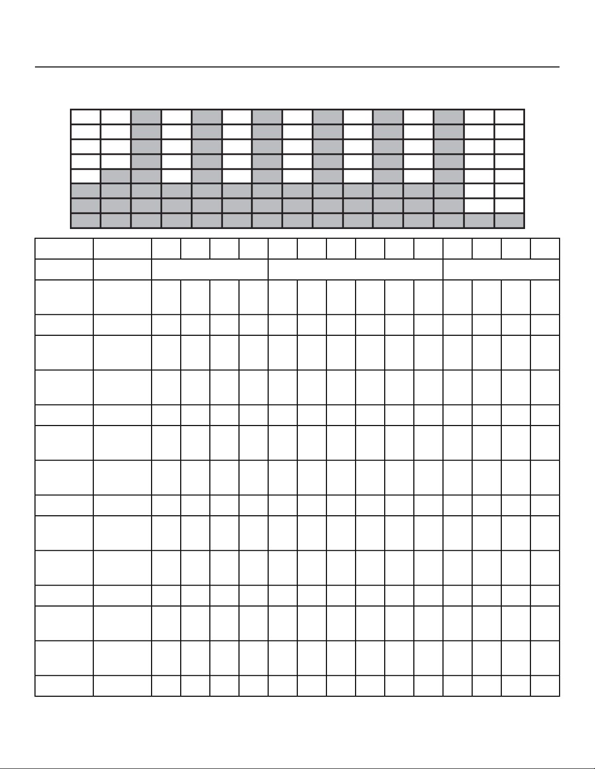
Strength - Bursts
Brief high-intensity segments are mixed with longer and easier intervals developing strength and aerobic
capacity.
:30:30:30:301:001:001:001:001:001:00:30:30:30:30Time
Cool DownCore SegmentsWarm UpLevel
3030404050805080508055555050
Resis-
tance
10
66661220182018201816146Incline10
10010010010080120110120110120110110100100
Target
Pace
10
2525353545754575457550504545
Resis-
tance
9
66661220182018201816146Incline9
10010010010080120110120110120110110100100
Target
Pace
9
2020303040704070407045454040
Resis-
tance
8
66661220182018201816146Incline8
10010010010080120110120110120110110100100
Target
Pace
8
1515252535653565356540403535
Resis-
tance
7
66661018161816181614126Incline7
10010010010080120110120110120110110100100
Target
Pace
7
1010202030603060306035353030
Resis-
tance
6
6666816141614161412106Incline6
Page 77 of 95
Cybex 771A/771AT, 772A/772AT Arc Trainer Part Number 5771-4 K

:30:30:30:301:001:001:001:001:001:00:30:30:30:30Time
Cool DownCore SegmentsWarm UpLevel
10010010010080120110120110120110110100100
Target
Pace
6
510151525552555255530302525
Resis-
tance
5
666661412141214121086Incline5
10010010010080120110120110120110110100100
Target
Pace
5
55101020502050205025252020
Resis-
tance
4
66664121012101210866Incline4
10010010010080120110120110120110110100100
Target
Pace
4
555515451545154520201515
Resis-
tance
3
66662108108108646Incline3
10010010010080120110120110120110110100100
Target
Pace
3
555510401040104015151515
Resis-
tance
2
66662108108108646Incline2
10010010010080120110120110120110110100100
Target
Pace
2
555553553553510101010
Resis-
tance
1
66662868686426Incline1
10010010010080120110120110120110110100100
Target
Pace
1
Page 78 of 95
Cybex 771A/771AT, 772A/772AT Arc Trainer Part Number 5771-4 K
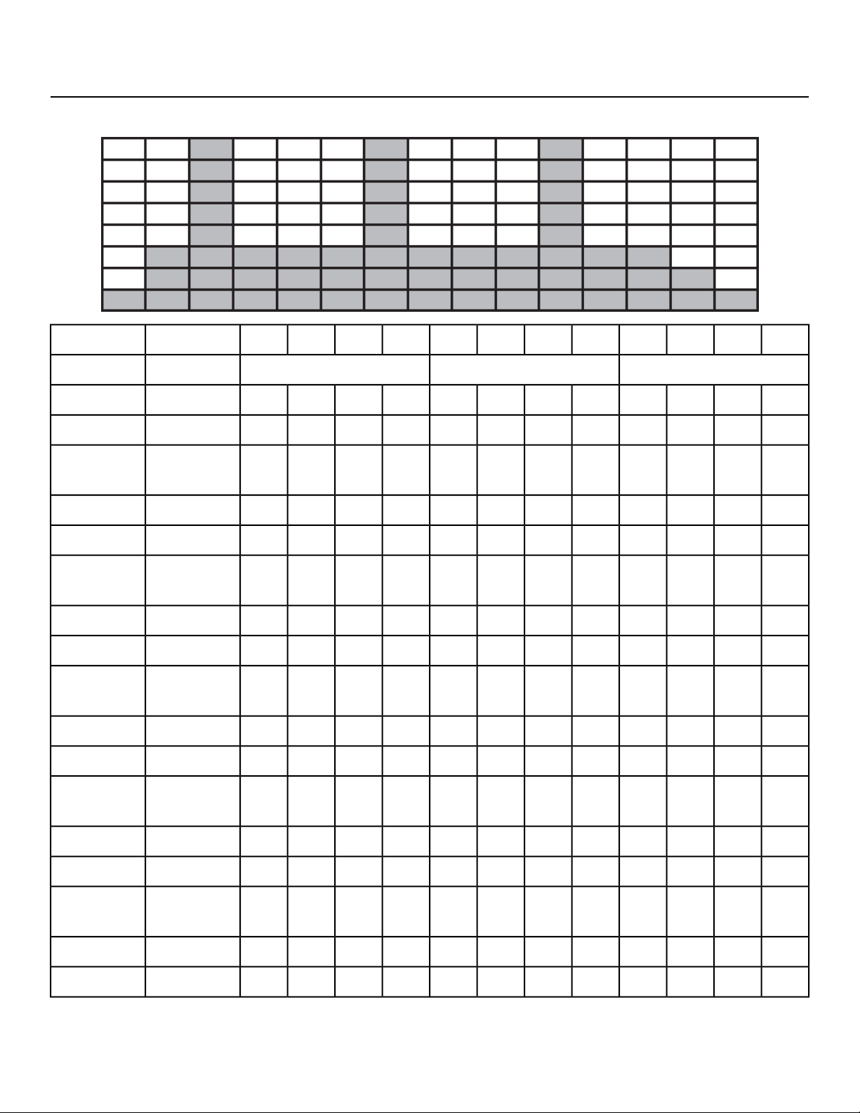
Strength - Interval
A repeating 15 second high intensity spike promotes strength gains
:30:30:30:301:001:001:001:00:30:30:30:30Time
Cool DownCore SegmentsWarm UpLevel
1520253035353510045403025Resistance10
6666202020201816126Incline10
100100100100808080120100100100100
Target
Pace
10
152025303535359540353025Resistance9
6666202020201816126Incline9
100100100100808080120100100100100
Target
Pace
9
152025303535359040353025Resistance8
6666181818181614126Incline8
100100100100808080120100100100100
Target
Pace
8
152020253030308540353025Resistance7
6666181818181614126Incline7
100100100100808080120100100100100
Target
Pace
7
152020253030308035302520Resistance6
6666181818181614126Incline6
100100100100808080120100100100100
Target
Pace
6
101520253030307535302520Resistance5
6666161616161412106Incline5
Page 79 of 95
Cybex 771A/771AT, 772A/772AT Arc Trainer Part Number 5771-4 K

:30:30:30:301:001:001:001:00:30:30:30:30Time
Cool DownCore SegmentsWarm UpLevel
100100100100808080120100100100100
Target
Pace
5
101520202525257035302520Resistance4
6666161616161412106Incline4
100100100100808080120100100100100
Target
Pace
4
101520202525256530252020Resistance3
6666161616161412106Incline3
100100100100808080120100100100100
Target
Pace
3
101015152020206030252015Resistance2
666614141414121086Incline2
100100100100808080120100100100100
Target
Pace
2
101015152020205525201515Resistance1
666614141414121086Incline1
100100100100808080120100100100100
Target
Pace
1
Page 80 of 95
Cybex 771A/771AT, 772A/772AT Arc Trainer Part Number 5771-4 K
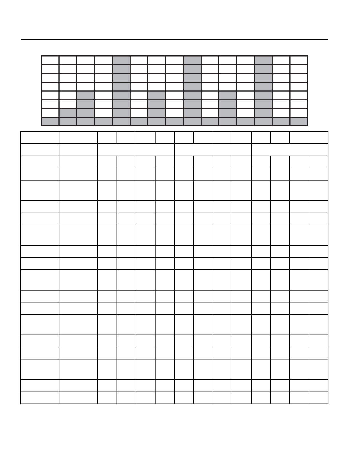
Fitness (Mens) , Shaping (Womens) - Total Leg
Alternating levels of resistance and incline change the targeted muscle group in an interval format.
:30:30:30:301:001:001:001:00:30:30:30:30Time
Cool DownCore SegmentsWarm UpLevel
202030303580406055504540Resistance10
66661020000006Incline10
100100100100100110100140130130120120
Target
Pace
10
202025253075355550454035Resistance9
66661020000006Incline9
100100100100100110100140130130120120
Target
Pace
9
151520202570305045403530Resistance8
6666918000006Incline8
100100100100100110100130120120110110
Target
Pace
8
101015152065254540353025Resistance7
6666918000000Incline7
100100100100100110100130120120110110
Target
Pace
7
5510101560204035302520Resistance6
6666816000006Incline6
100100100100100110100120120120110110
Target
Pace
6
00551055153530252015Resistance5
6666814000006Incline5
Page 81 of 95
Cybex 771A/771AT, 772A/772AT Arc Trainer Part Number 5771-4 K

:30:30:30:301:001:001:001:00:30:30:30:30Time
Cool DownCore SegmentsWarm UpLevel
100100100100100110100110110110100100
Target
Pace
5
00551050153025201510Resistance4
6666712022246Incline4
100100100100100100801001001008080
Target
Pace
4
0055103015252015105Resistance3
6666710022246Incline3
100100100100100100801001001008080
Target
Pace
3
00555251020151050Resistance2
6666610024466Incline2
8080808080100801001001008080
Target
Pace
2
0055520101510500Resistance1
666668024466Incline1
8080808080100801001001008080
Target
Pace
1
Page 82 of 95
Cybex 771A/771AT, 772A/772AT Arc Trainer Part Number 5771-4 K
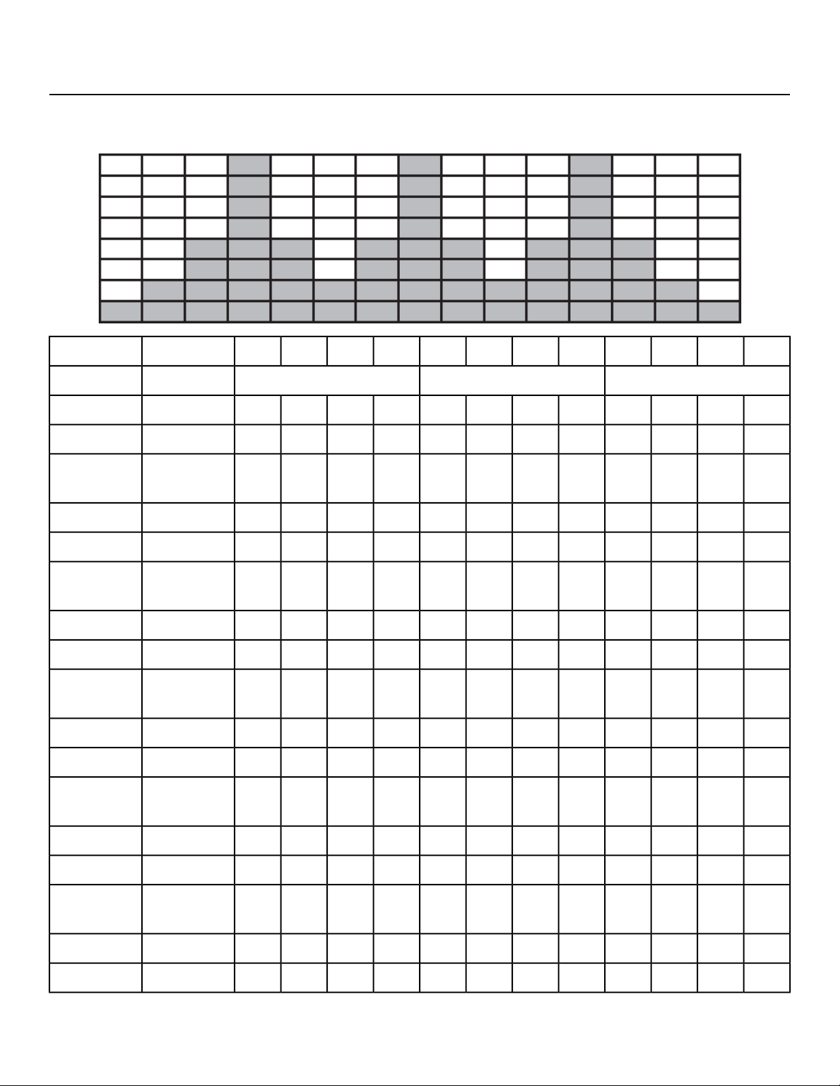
Fitness (Mens) - Target: Hip, Shaping (Womens) - Glute Camp
2 minutes of progressive resistance and incline targeting the hip extensors are followed by a 1 minute
rest.
:30:30:30:301:001:001:001:00:30:30:30:30Time
Cool DownCore SegmentsWarm UpLevel
202525303060755550454035Resistance10
66661221220006Incline10
100100100100100140100120110110100100
Target
Pace
10
152020252555705045403530Resistance9
66661221220006Incline9
100100100100100140100120110110100100
Target
Pace
9
152020252550654540353025Resistance8
66661001000006Incline8
100100100100100140100120110110100100
Target
Pace
8
101515202045604035302520Resistance7
66661001000006Incline7
100100100100100140100120110110100100
Target
Pace
7
101515202040553530252015Resistance6
666680800006Incline6
1001001001001001301001101101008080
Target
Pace
6
51010151535503025201510Resistance5
666680800006Incline5
Page 83 of 95
Cybex 771A/771AT, 772A/772AT Arc Trainer Part Number 5771-4 K

:30:30:30:301:001:001:001:00:30:30:30:30Time
Cool DownCore SegmentsWarm UpLevel
80808080801301001101101008080
Target
Pace
5
5101015153045252015105Resistance4
66661041040006Incline4
80808080801201001001001008080
Target
Pace
4
510101515254020151050Resistance3
66661041040006Incline3
80808080801201001001001008080
Target
Pace
3
055101020351510550Resistance2
66661041040006Incline2
80808080801201001001001008080
Target
Pace
2
005551530105500Resistance1
66661041040006Incline1
80808080801201001001001008080
Target
Pace
1
Page 84 of 95
Cybex 771A/771AT, 772A/772AT Arc Trainer Part Number 5771-4 K
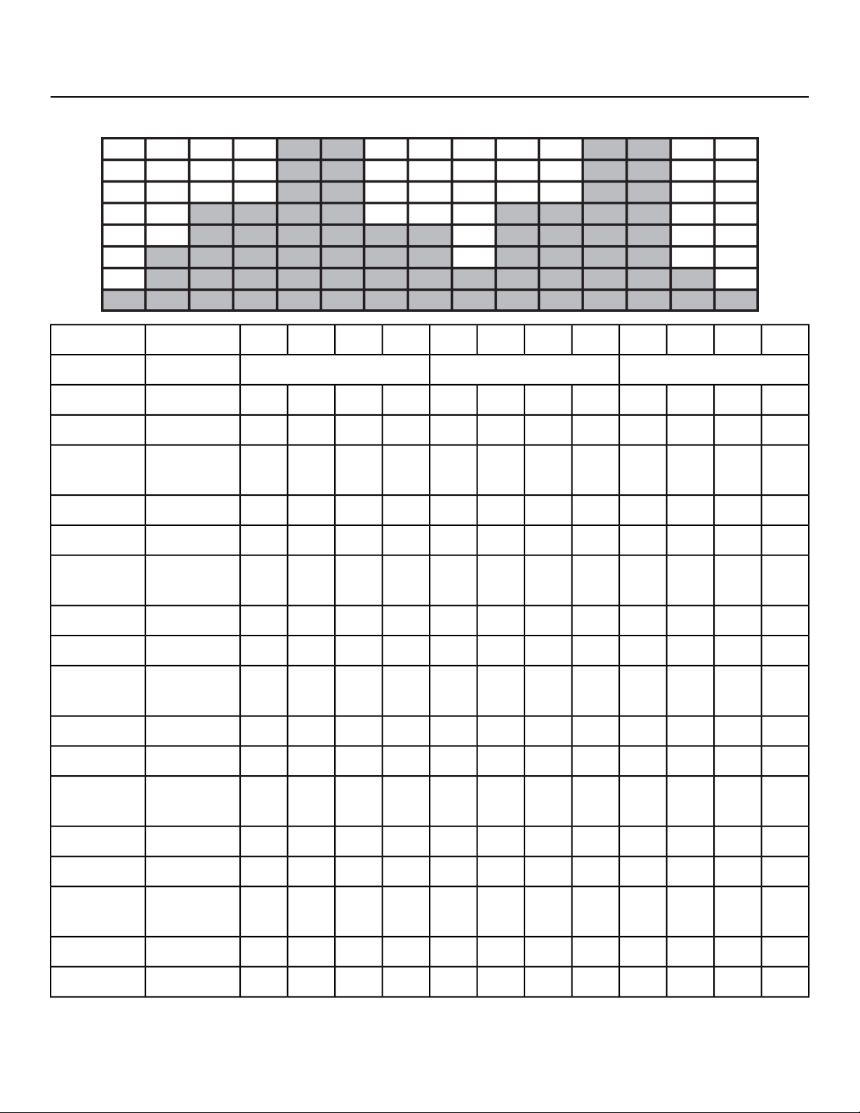
Cardio - Wave
A long duration interval promotes cardio endurance with enough rest to repeat the process.
:30:30:30:301:001:001:001:00:30:30:30:30Time
Cool DownCore SegmentsWarm UpLevel
202025252535754545403530Resistance10
666661220181616146Incline10
808010010010014012012012011010080
Target
Pace
10
151520202030653535302520Resistance9
666661418161412106Incline9
8080100100100140120120120110110100
Target
Pace
9
101015151525553030252020Resistance8
66664121614121086Incline8
8080100100100140120120120110110100
Target
Pace
8
101015151525503030252015Resistance7
6666410141210866Incline7
8080100100100130120110110110100100
Target
Pace
7
101015151520402525201515Resistance6
66662812108646Incline6
8080100100100130110110110110100100
Target
Pace
6
101015151520352525201510Resistance5
6666261086426Incline5
Page 85 of 95
Cybex 771A/771AT, 772A/772AT Arc Trainer Part Number 5771-4 K

:30:30:30:301:001:001:001:00:30:30:30:30Time
Cool DownCore SegmentsWarm UpLevel
80801001001001201101001001008080
Target
Pace
5
5510101015252020151010Resistance4
666604864426Incline4
80808080801201101001001008080
Target
Pace
4
55101010152020151050Resistance3
666602644426Incline3
80808080801201101001001008080
Target
Pace
3
5555510101510500Resistance2
666600422206Incline2
80808080801101001001001008080
Target
Pace
2
5555555105500Resistance1
666600200006Incline1
80808080801101001001001008080
Target
Pace
1
Page 86 of 95
Cybex 771A/771AT, 772A/772AT Arc Trainer Part Number 5771-4 K
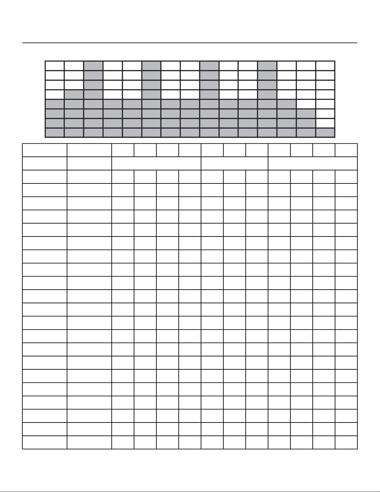
Cardio - Interval
A 30 second charge improves aerobic power with 1 minute of recovery before a repeat.
:30:30:30:301:001:001:00:30:30:30:30Time
Cool DownCore SegmentsWarm UpLevel
2030354045457065554535Resistance10
66661414141212106Incline10
100100110110110110140140140130120Target Pace10
1525303540406560504035Resistance9
66661414141212106Incline9
100100110110110110140140140130120Target Pace9
1520253035356055504030Resistance8
6666121212101086Incline8
100100110110110110130130130120110Target Pace8
1020253030305550453530Resistance7
6666121212101086Incline7
8080110110110110130130130120110Target Pace7
1020253030305045403525Resistance6
66661010108866Incline6
8080110100100100120120120110100Target Pace6
1015202525254540353025Resistance5
66661010108866Incline5
8080110100100100120120120110100Target Pace5
1015202525254035302520Resistance4
66668886646Incline4
80808010010010011011011010080Target Pace4
Page 87 of 95
Cybex 771A/771AT, 772A/772AT Arc Trainer Part Number 5771-4 K

:30:30:30:301:001:001:00:30:30:30:30Time
Cool DownCore SegmentsWarm UpLevel
1010152020203530302520Resistance3
66668886646Incline3
80808010010010011011011010080Target Pace3
510152020203025252015Resistance2
66666664426Incline2
8080801001001001001001008080Target Pace2
510151515152520201510Resistance1
66666664426Incline1
8080801001001001001001008080Target Pace1
Page 88 of 95
Cybex 771A/771AT, 772A/772AT Arc Trainer Part Number 5771-4 K
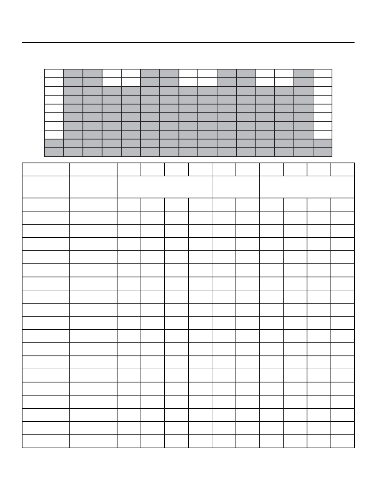
Cardio - Hill Interval
Moderate duration intervals with changes in incline and resistance promote cardio endurance with
enough rest to repeat the process.
:30:30:30:302:002:00:30:30:30:30Time
Cool DownCore Seg-
ments
Warm UpLevel
20253035604035302520Resistance10
6810122012121086Incline10
100100100100120100100100100100Target Pace10
20253035504035302520Resistance9
66810201010866Incline9
100100100100120100100100100100Target Pace9
15202530453530252015Resistance8
66810181010866Incline8
100100100100120100100100100100Target Pace8
15202530403530252015Resistance7
66810181010866Incline7
100100100100120100100100100100Target Pace7
15152025353025201515Resistance6
66681688666Incline6
100100100100120100100100100100Target Pace6
15152025352525201515Resistance5
66661666666Incline5
808080801008080808080Target Pace5
10101520302520151010Resistance4
Page 89 of 95
Cybex 771A/771AT, 772A/772AT Arc Trainer Part Number 5771-4 K

:30:30:30:302:002:00:30:30:30:30Time
Cool DownCore Seg-
ments
Warm UpLevel
66661466666Incline4
808080801008080808080Target Pace4
10101520252520151010Resistance3
44661466644Incline3
808080801008080808080Target Pace3
10101015252015101010Resistance2
44661266644Incline2
808080801008080808080Target Pace2
10101010201510101010Resistance1
44661266644Incline1
808080801008080808080Target Pace1
Page 90 of 95
Cybex 771A/771AT, 772A/772AT Arc Trainer Part Number 5771-4 K

Cardio - Heart Rate Control
The Heartrate Control (HRC) workout will attempt to bring the user to their target heartrate in 3-5 minutes,
then keep them there for the duration of the body of the program. A Cool Down is built in to the end of
the program. HRC is run in Constant Power and thus defines watts.
Note: This workout requires the user to wear a 5 KHz Polar
®
or compatible heart rate transmitter
belt. The Heart Rate Control workout (HRC) cannot be selected on the control console unless it
detects a heart rate signal. The HRC workout will not work with the cardio touch contact heart
rate system.
The user selects a target heartrate, which defaults to 75% of max. Limits should be set to not allow a
Target HR (THR) less than 60% of max or more than 95% of max.
Max HR formula: 208-(0.7 x Age).
The protocol starts in Stage II, with the entry point based on Target HR.
• 80 – 120 BPM = Step 6
• 121-127 BPM = Step 8
• 128-134 BPM = Step 10
• 135-up BPM = Step 12
A running pulse-to-pulse BPM value is continuously measured.
Every 15 seconds the user’s pulse rate is sampled and a prediction function is evaluated (decision.)
This is subtracted from the target heartrate to form an error value which is scaled and added to the
current load value. There is a maximum rate of change of 15 steps per decision.
A chart of Step and Watts has been created. It has four defined stages:
• Stage 1 ramps the load from Step 1 to Step 5.
• Stage 2 ramps the load from Step 6 through Step 18.
• Stage 3 ramps the load from Step 19 through Step 39.
• Stage 4 ramps the load from Step 40 through Step 100.
The user has full control over incline throughout the program, with incline having no bearing on the
program at all. The user has limited control over the load in that the user’s selections are not permanent.
At the next decision, a new load can be chosen by the software as described above to override any
user modifications.
If the user presses the LEVEL key, they can modify their Target Heartrate real-time. Utilize the Target
Heartrate Setup selection screen and exit back to the program in progress, making the change to their
target heartrate real-time.
Lost Signal
If a signal is lost for two consecutive decisions (roughly 30 seconds), the display will beep four times,
show HR SIGNAL LOST, show dashes in the BPM window and show the heart solid white. During this
HR signal lost period, the load will remain steady.
Page 91 of 95
Cybex 771A/771AT, 772A/772AT Arc Trainer Part Number 5771-4 K

If after two further decisions (roughly an additional 30 seconds) the heartrate signal has not been
reestablished, continue to show HR SIGNAL LOST on the Text area. The program will reduce the
workload by 10 steps per minute until minimum workload or Step 1. After one minute at minimum
workload, go to Exiting Active Mode.
Cool Down
By default, Cool Down occurs at session time minus two minutes. Cool Down goes to 75% of existing
step, then drops by 1 step every 15 seconds for the remainder of Cool Down.
Page 92 of 95
Cybex 771A/771AT, 772A/772AT Arc Trainer Part Number 5771-4 K

Power - Constant Power
You set the power in watts. Pedaling faster feels easier, pedaling slower feels harder; but the workload
remains the same.
Page 93 of 95
Cybex 771A/771AT, 772A/772AT Arc Trainer Part Number 5771-4 K

Power - Adaptive Power
An ideal way to perform “live” interval training. You choose the level. The higher the level, the greater
the rate the resistance increases with speed.
Page 94 of 95
Cybex 771A/771AT, 772A/772AT Arc Trainer Part Number 5771-4 K

10 Trotter Drive, Medway, MA 02053 • 888-462-9239 • 508-533-4300 • FAX 508-533-5183
www.cybexintl.com