SPARC
®
50A1 Owner's Manual
Part Number
50A1-999-4 AC


Corporate Headquarters
Columbia Centre III, 9525 Bryn Mawr Avenue, Rosemont, Illinois 60018 • U.S.A.
847.288.3300 • FAX: 847.288.3703
Service phone number: 800.351.3737 (toll-free within U.S.A., Canada)
Global Website: www.cybexintl.com
International Oices
AMERICAS
North America
Cybex International Inc.
Columbia Centre III
9525 Bryn Mawr Avenue
Rosemont, IL 60018 U.S.A.
Telephone: (847) 288 3300
Service Email: [email protected]om
Sales/Marketing Email:
commercialsales@lifefitness.com
United Kingdom
Life Fitness UK LTD
Queen Adelaide
Ely, Cambs, CB7 4UB
Telephone: General Oice (+44) 1353.666017
Customer Support (+44) 1353.665507
Service Email: [email protected]
Sales/Marketing Email: life@lifefitness.com
All Other EMEA Countries and Distributor Business EMEA*
Bijdorpplein 25-31
2992 LB Barendrecht
THE NETHERLANDS
Telephone: (+31) 180 646 644
Service Email: EMEAService[email protected]
Brazil
Life Fitness Brasil
Av. Rebouças, 2315
Pinheiros
São Paulo, SP 05401-300
BRAZIL
SAC: 0800 773 8282 option 2
Telephone: +55 (11) 3095 5200 option 2
Service Email: [email protected]om
Sales/Marketing Email: vendasbr@lifefitness.com
Germany, Austria, and Switzerland
Life Fitness Europe GMBH
Neuhofweg 9
85716 Unterschleißheim
GERMANY
Telephone:
+49 (0) 89 / 31775166 Germany
+43 (0) 1 / 6157198 Austria
+41 (0) 848 / 000901 Switzerland
Service Email: [email protected]om
Sales/Marketing Email: vertrieb@lifefitness.com
ASIA PACIFIC (AP)
Japan
Life Fitness Japan, Ltd
4-17-33 Minami Aoyama 1F/B1F
Minato-ku - Tokyo 107-0062
Japan
Telephone: (+81) 0120.114.482
Fax: (+81) 03-5770-5059
Service Email: service.lfj@lifefitness.com
Sales/Marketing Email: sales@lifefitnessjapan.com
Latin America and Caribbean*
Life Fitness, LLC
Columbia Centre III
9525 Bryn Mawr Avenue
Rosemont, IL 60018 U.S.A.
Telephone: (847) 288 3300
Service Email: [email protected]om
Sales/Marketing Email:
commercialsales@lifefitness.com
Spain
Life Fitness IBERIA
C/Frederic Mompou 5,1º1ª
08960 Sant Just Desvern Barcelona
SPAIN
Telephone: (+34) 93.672.4660
Service Email: servicio.tecnico@lifefitness.com
Sales/Marketing Email: info[email protected]
Hong Kong
Life Fitness Asia Pacific LTD
32/F, Global Trade Square
21 Wong Chuk Hang Road
Hong Kong
Telephone: (+852) 2575.6262
Service Email: Service.HK@lifefitness.com
Sales/Marketing Email: hongkong.sales@lifefitness.com
EUROPE, MIDDLE EAST, and AFRICA (EMEA)
Netherlands and Luxemburg
Life Fitness Atlantic BV
Bijdorpplein 25-31
2992 LB Barendrecht
THE NETHERLANDS
Telephone: (+31) 180 646 666
Service Email: service.benelux@lifefitness.com
Sales/Marketing Email:
marketing.benelux@lifefitness.com
Belgium
Life Fitness Benelux NV
Parc Industrial de Petit-Rechain
4800 Verviers
BELGIUM
Telephone: (+32) 87 300 942
Service Email: service.benelux@lifefitness.com
Sales/Marketing Email:
marketing.benelux@lifefitness.com
All Other Asia Pacific countries and distributor business Asia
Pacific*
32/F, Global Trade Square
21 Wong Chuk Hang Road
Hong Kong
Telephone: (+852) 2575.6262
Fax: (+852) 2575.6894
Service Email: Service.AP@lifefitness.com
Sales/Marketing Email:
Marketing.HK.Asia@lifefitness.com
*Also check www.cybexintl.com for local representation or distributor/dealer
Page 1 of 36

User and Service Documents Link
https://lifefitness9512.zendesk.com/hc/en-us
https://lfworld.lifefitness.com
Additional information is available online using the links above.
.
点击上面的链接可在线获取更多信息。
Flere oplysninger er tilgængelige online gennem linket ovenfor.
Bijkomende informatie is online beschikbaar via bovenstaande link.
Vous trouverez plus d'informations en ligne à l'aide du lien ci-dessus.
Zusätzliche Informationen finden Sie online über den oben angegebenen Link.
Ulteriori informazioni sono disponibili online utilizzando il link sopra riportato.
追加情報は上記リンクを使用してオンラインで利用可能です。
상기 링크를 통해 온라인에서 추가 정보를 볼 수 있습니다.
Informações adicionais estão disponíveis on-line, através do link acima.
Дополнительная информация до ступна в интернете по ссылке, указанной выше.
Mediante el enlace anterior podrá acceder a información adicional en línea.
Ytterligare information finns online genom att använda länken ovan.
İnternet daha fazla bağlantıyı
.
Informazio osagarria eskuragarri dago goiko estekaren bidez.
Допълнителна информация можете да намерите онлайн, като използвате връзката по-горе.
Mitjançant l'enllaç anterior podreu accedir a informació addicional en línia.
使用上面的連結線上提供額外資訊。
Dodatne informacije možete pronaći na internetu sljedeći vezu iznad.
ከላይ የተቀመጠውን አገናኝ(ሊንክ) በመጠቀም መረጃዎች ኦንላይን ያገኛሉ
Lisätietoja on saatavissa verkosta käyttämällä yllä olevaa linkkiä.
Wubetumi anya nsɛm afoforo aka ho wɔ wɛbsait so denam asɛm a ɛwɔ atifi hɔ a wubemia so so.
Πρόσθετες πληροφορίες είναι διαθέσιμες ονλάιν χρησιμοποιώντας το σύνδεσμο παραπάνω.
. עדימ ףסונ רשפא לבקל טנרטניאב תועצמאב רושיקה ליעל
További információ elérhető online, a fenti hivatkozás segítségével.
Viðbótarupplýsingar eru fáanlegar á netinu með því að smella á tengilinn hér fyrir ofan.
Plus indicium per superum situm potes invenire.
.
Ytterligere informasjon er tilgjengelig på nettet via linken ovenfor.
Dodatkowe informacje są dostępne online pod powyższym odnośnikiem.
Informações adicionais estão disponíveis online a usar o link acima.
Informații suplimentare sunt disponibile online, utilizând link-ul de mai sus.
Dodatne informacije dostupne su na mreži putem gornjeg linka.
Ďalšie informácie sú dostupné online na vyššie uvedenom odkaze.
Page 2 of 36

Table of Contents
Safety
Safety Instructions.........................................................................................................................................................................................................5
Warnings and Cautions................................................................................................................................................................................................ 7
Label Placement............................................................................................................................................................................................................8
Assembly
Specifications - 50A1.....................................................................................................................................................................................................9
Top View - 50A1............................................................................................................................................................................................................10
Choosing and Preparing Site.................................................................................................................................................................................... 10
Environment.................................................................................................................................................................................................................11
Assembly Procedure...................................................................................................................................................................................................11
Setup..............................................................................................................................................................................................................................18
Calibrate Resistance Level.........................................................................................................................................................................................18
Testing Operation........................................................................................................................................................................................................19
Operation
Individual Human Power Versus Mechanical Power............................................................................................................................................21
Intended Use................................................................................................................................................................................................................21
Terms Used...................................................................................................................................................................................................................21
User Controls................................................................................................................................................................................................................21
Incline Lever................................................................................................................................................................................................................. 22
Resistance Lever..........................................................................................................................................................................................................24
Mount and Dismount..................................................................................................................................................................................................24
Quick Operation Guide...............................................................................................................................................................................................24
Detailed Operation Guide..........................................................................................................................................................................................25
Results........................................................................................................................................................................................................................... 27
How power input versus displayed value is calculated.......................................................................................................................................28
Maintenance
Warnings....................................................................................................................................................................................................................... 29
Clean Unit..................................................................................................................................................................................................................... 29
Batteries........................................................................................................................................................................................................................29
Service Schedule.........................................................................................................................................................................................................32
Customer Service
Product Registration...................................................................................................................................................................................................34
Contacting Service......................................................................................................................................................................................................34
Ordering Parts..............................................................................................................................................................................................................34
Return Material Authorization (RMA).......................................................................................................................................................................34
Damaged Parts............................................................................................................................................................................................................ 35
Cybex
®
and the Cybex logo are registered trademarks of Cybex International, Inc.
DISCLAIMER: Cybex International, Inc. makes no representations or warranties regarding the contents of this manual. We reserve the right to revise this
document at any time or to make changes to the product described within it without notice or obligation to notify any person of such revisions or
changes.
©
Copyright 2021, Life Fitness, LLC. All Rights Reserved. Life Fitness, Hammer Strength, Cybex, ICG and SCIFIT are registered trademarks of Life Fitness,
LLC and its companies and subsidiaries. Brunswick and related trademarks used under license from Brunswick Corporation. Disclaimer: Images
and specifications are current as of the date of publication and are subject to change.
Columbia Center III - 9525 Bryn Mawr Ave, Rosemont, IL 60018 • 800-351-3737 • 847-288-3700 • FAX 800-216-8893
www.cybexintl.com • 50A1-999-4 AC • 2021
Page 3 of 36

FCC Compliance Information
Changes or modifications to this unit not expressly approved by the party responsible for compliance could void the user’s authority to
operate the equipment.
This equipment has been tested and found to comply with the limits for a Class B digital device, pursuant to part 15 of the FCC Rules.
These limits are designed to provide reasonable protection against harmful interference in a residential installation. This equipment
generates, uses and can radiate radio frequency energy and, if not installed and used in accordance with the instructions, may cause
harmful interference to radio communications. However, there is no guarantee that interference will not occur in a particular
installation. If this equipment does cause harmful interference to radio or television reception, which can be determined by turning the
equipment o and on, the user is encouraged to try to correct the interference by one or more of the following measures:
• Reorient or relocate the receiving antenna.
• Increase the separation between the equipment and receiver.
• Connect the equipment into an outlet on a circuit dierent from that to which the receiver is connected.
• Consult the dealer or an experienced radio/TV technician for help.
Page 4 of 36

Safety
Safety Instructions
Read all instructions before use.
Please take special note of the following safety instructions and important points prior to choosing a location and beginning assembly
of the product.
WARNING: Health-related injuries may result from incorrect or excessive use of exercise equipment. Life Fitness Family of
Brands STRONGLY recommends seeing a physician for a complete medical exam before undertaking an exercise program,
particularly if the user has a family history of high blood pressure or heart disease, is over the age of 45, smokes, has high
cholesterol, is obese, or has not exercised regularly in the past year. If, at any time while exercising, the user experiences
faintness, dizziness, pain, or shortness of breath, he or she must stop immediately.
WARNING: Obtain instruction before using.
WARNING: Serious injury or death could occur if the following safety precautions and instructions are not followed.
WARNING: To reduce the risk of burns, fire, electric shock, or injury, it is imperative to connect each product to a properly
grounded electrical outlet.
WARNING: Heart rate monitoring systems may be inaccurate. Over exercising may result in serious injury or death. If you feel
faint, stop exercising immediately.
WARNING: Ensure that there is at least 23.6" (0.6 m) of clearance behind the product and at least 12" (30 cm) on the sides.
WARNING: Inspect unit. If damaged, notify floor sta. DO NOT USE.
WARNING: Maximum user weight is 400 lbs. (180 kg).
WARNING: Do not use for stretching and do not attach straps or other devices.
WARNING: Use the handrails for support and to maintain balance.
WARNING: The product is not equipped with a free-wheeling feature. Therefore, it cannot be stopped immediately.
WARNING: Moving parts and fall hazard.
• To avoid serious injury wait until foot plates come to a complete stop before getting o unit.
• The moving parts cannot be stopped immediately, the unit is not equipped with a free wheel.
WARNING: Keep foot plate surface clean and dry.
WARNING: This product can expose you to chemicals including Di-2-ethylhexyl-phthalate, which is known to the State of
California to cause cancer and birth defects or other reproductive harm. For more information go to http://
www.P65Warnings.ca.gov
DANGER: To reduce the risk of electrical shock or injury from moving parts, always unplug product before cleaning or
attempting any maintenance activity.
• Keep all loose clothing, shoelaces, and towels away from moving parts.
• The individual human power required to perform an exercise may be dierent than the mechanical power displayed on the
product.
• Use caution when mounting or dismounting the product. Before mounting, use the moving arms to bring the foot plate nearest to
you to the lowest position. Use the stationary handlebars whenever additional stability is required. While exercising, hold onto the
moving arms.
• Never face backward while using the product.
• Do not stand or sit on the rear plastic covers of the product.
• Never operate the product if it has a damaged power cord or electrical plug, or if it has been dropped, damaged, or even partially
immersed in water. Contact Customer Support Services.
• Position the product so that the power cord plug to the wall is accessible to the user. Make sure that the power cord is not knotted
or twisted and that it is not trapped under any equipment or other objects.
Page 5 of 36

• If the electrical supply cord is damaged, it must be replaced by the manufacturer, an authorized service agent, or a similarly
qualified person to avoid a hazard.
• Always follow the console instructions for proper operation.
• This appliance is not intended for use by persons (including children) with reduced physical, sensory, or mental capabilities, or lack
of experience or knowledge unless they have supervision or been given instruction concerning the use of the appliance by a person
responsible for their safety.
• This equipment is not intended for use by children. Keep children under the age of 14 away from the machine.
• Do not use this product outdoors, near swimming pools or in areas of high humidity.
• Never operate the product with the air openings blocked. Keep air openings free of lint, hair, or any other obstructing material.
• Never insert objects into any opening in these products. If an object should drop inside, turn o the power, unplug the power cord
from the outlet, and carefully retrieve it. If the item cannot be reached, contact Customer Support Services.
• Never place liquids of any type directly on the unit, except in an accessory tray or holder. Containers with lids are recommended.
• Do not use these products in bare feet. Always wear shoes. Wear shoes with rubber or high-traction soles. Do not use shoes with
heels, leather soles, cleats or spikes. Make sure no stones are embedded in the soles.
• Do not reach into, or underneath, the unit or tip it on its side during operation.
• Do not allow other people to interfere in any way with the user or equipment during a workout.
• Use these products for their intended use as described in this manual. Do not use attachments that have not been recommended
by the manufacturer.
• Read all warnings on each product prior to starting a workout.
• If warnings are missing or damaged, please contact Customer Support Services immediately for replacement warning labels.
Warning labels are shipped with every product and should be installed before product is used. Life Fitness is not responsible for
missing or damaged warning labels.
SAVE THESE INSTRUCTIONS FOR FUTURE REFERENCE.
Page 6 of 36
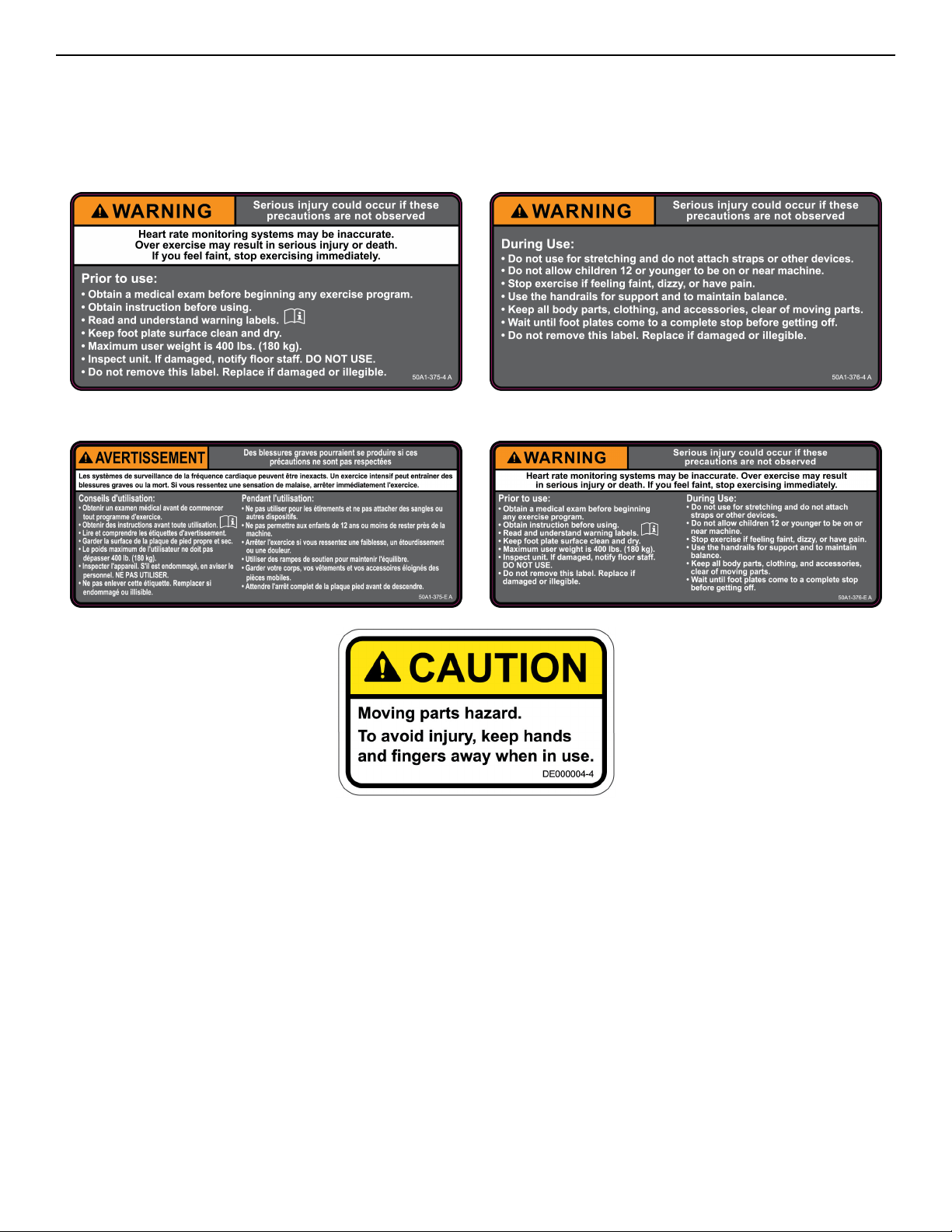
Warnings and Cautions
Warning labels indicate a potentially hazardous situation that could result in serious injury or death if the precautions are not
observed.
Caution labels indicate a potentially hazardous situation that could result in serious injury or damage to machine if the precautions
are not observed.
Contact Customer Support Services to replace any worn or damaged labels.
Canadian
Page 7 of 36
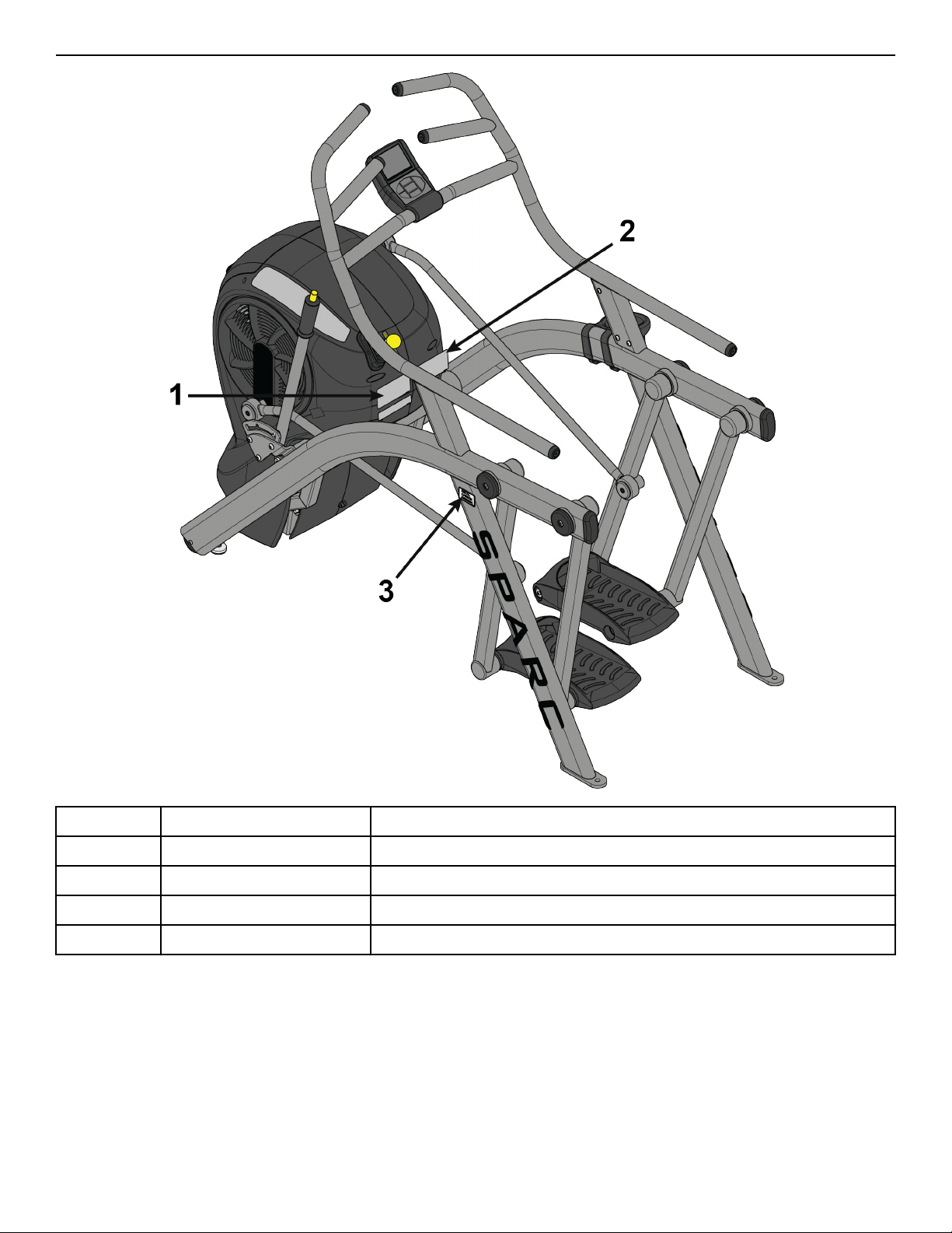
Label Placement
1 50A1-375-X Label, Warning, Le
1 50A1-375-E Label, Warning, Le, Canadian
2 50A1-376-X Label, Warning, Right
2 50A1-376-E Label, Warning, Right, Canadian
3 DE000004-X Decal, Caution
Page 8 of 36

Assembly
Specifications - 50A1
Classification EN ISO 20957 Class S (Studio)
Accuracy A
Assembled Length 71" (180 cm)
Assembled Width 34.7" (88 cm)
Assembled Height 60.6" (154 cm)
Weight of Product 285 lbs. (129 kg)
Shipping Weight 350 lbs. (158 kg)
Incline Levels 0, 6, 12 % grade
Resistance Levels 1-10 levels of brake resistance
Resistance Range Fan 0-1000 watts, Resistance Lever (ECB) adds additional 0-400 watts
Braking System Brushless Eddy current brake, speed independent
Stride Length 24” (61 cm) fixed length
Workouts Circuit and Interval
Display Screen LCD - Liquid Crystal Display
Console Features
Graphic Display: Brake resistance level meter
Numeric display: Meters/Km, Seconds (Countdown), SPM (Strides Per Minute), Time, Total time,
Watts.
Frame Colors
Standard: White Texture, Black Texture, Metaltone Gold, Black Chrome, Platinum Sparkle.
Custom: Unlimited colors available.
Maximum User Weight 400 lbs. (180 kg).
Power Supply Two D-Cell 1.5 v Alkaline batteries
Other Water bottle holder.
Page 9 of 36
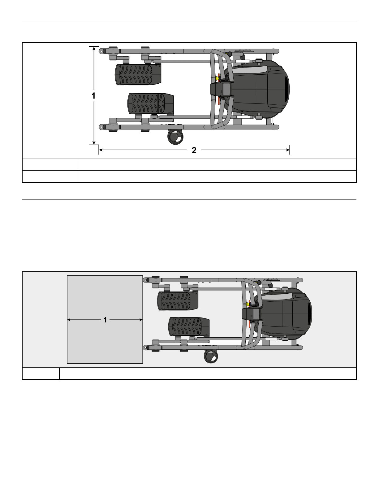
Top View - 50A1
Dimensions
1 34.7” (88 cm)
2 71” (180 cm)
Choosing and Preparing Site
Before assembling the unit, verify the chosen site meets the following criteria:
• Area is well lit and well ventilated.
• Surface is structurally sound and properly leveled.
• Free area for access to unit and emergency dismount. Minimum clearance is 23.6 inches (0.6 meters).
• Adjacent units may share the free area.
Free Area
1 23.6”, 0.6m
It is the responsibility of the facility owner/owner of the equipment to ensure that there is appropriate clearance around each machine
to allow for safe use and passage.
In compliance with the ADA (American Disabilities Act) there must be clear floor space of at least 30 by 48 inches and be served by an
accessible route for at least one of each type of exercise equipment. If the clear space is enclosed on three sides (e.g., by walls or the
equipment itself), the clear space must be 36 by 48 inches.
All other machines must have a clear floor space of 23" for all access point on the machine.
The dimensions stated in the assembly instructions of this manual include the maximum foot print (in use) dimensions.
Minimum clearance of 12” (30 cm) between units for proper wireless heart rate signal operation.
Page 10 of 36

Environment
Humidity and Static Electricity
The unit is designed to function normally in an environment with a relative humidity range of 30% to 75%. The unit can be shipped
and stored in a relative humidity range of 10% to 90%.
Climatic dry air may cause static electricity. During workout, user may experience a shock due to build up of static electricity on the
body and the discharge path of the unit. If static electricity is experienced, increase humidity to a comfortable level through the use of
a humidifier.
Do not install, use or store the unit in an area of high humidity, such as in the vicinity of a steam room, sauna, indoor pool or outdoors.
Exposure to extensive water vapor, chlorine and/or bromine could adversely aect the electronics as well as other parts of the unit.
Temperature
The unit is designed to function normally in an environment with an ambient temperature range of 50° F (10° C) to 104° F (40° C). The
unit can be shipped and stored in an environment with an ambient temperature range of 32° F (0° C) to 140° F (60° C).
Assembly Procedure
Two people will be required for this procedure.
TIP: Read and understand all instructions thoroughly before assembling this unit. Check all items carefully. If there is damage, see the
Customer Service section of this manual for proper procedure to return, replace, or reorder parts.
The words "le" and "right" denote the user's orientation.
Verify you have received the correct package
1. Read box label to verify the model number and voltage (optional) match what was ordered.
2. Verify paint color matches what was ordered.
Tools Required
• 3/16” Allen wrench
• Phillips screwdriver
• 1/2” Open end wrench
• 9/16” Open end wrench
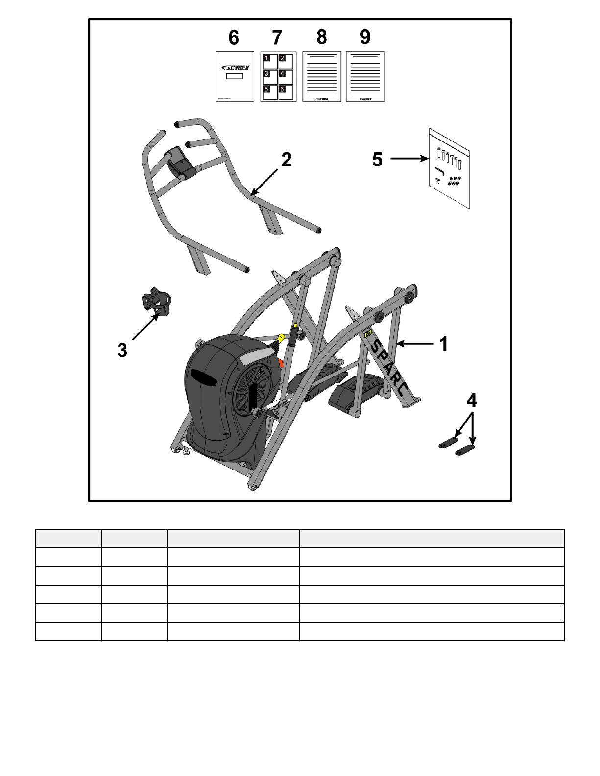
Verify Parts List Shown Below
Item Quantity Part Number Description
1 1 Varies Base assembly
2 1 Varies Handrail assembly
3 1 PL-17209 Water bottle holder
4 2 12090-322 Foot pad
5 1 K50A1-106 Hardware kit
6 1 50A1-999-X Owner’s Manual
7 1 50A1-369 Assembly poster
8 1 50A1-371 Consumer Arc warranty sheet
9 1 50A1-370 Commercial Arc warranty sheet
Page 11 of 36
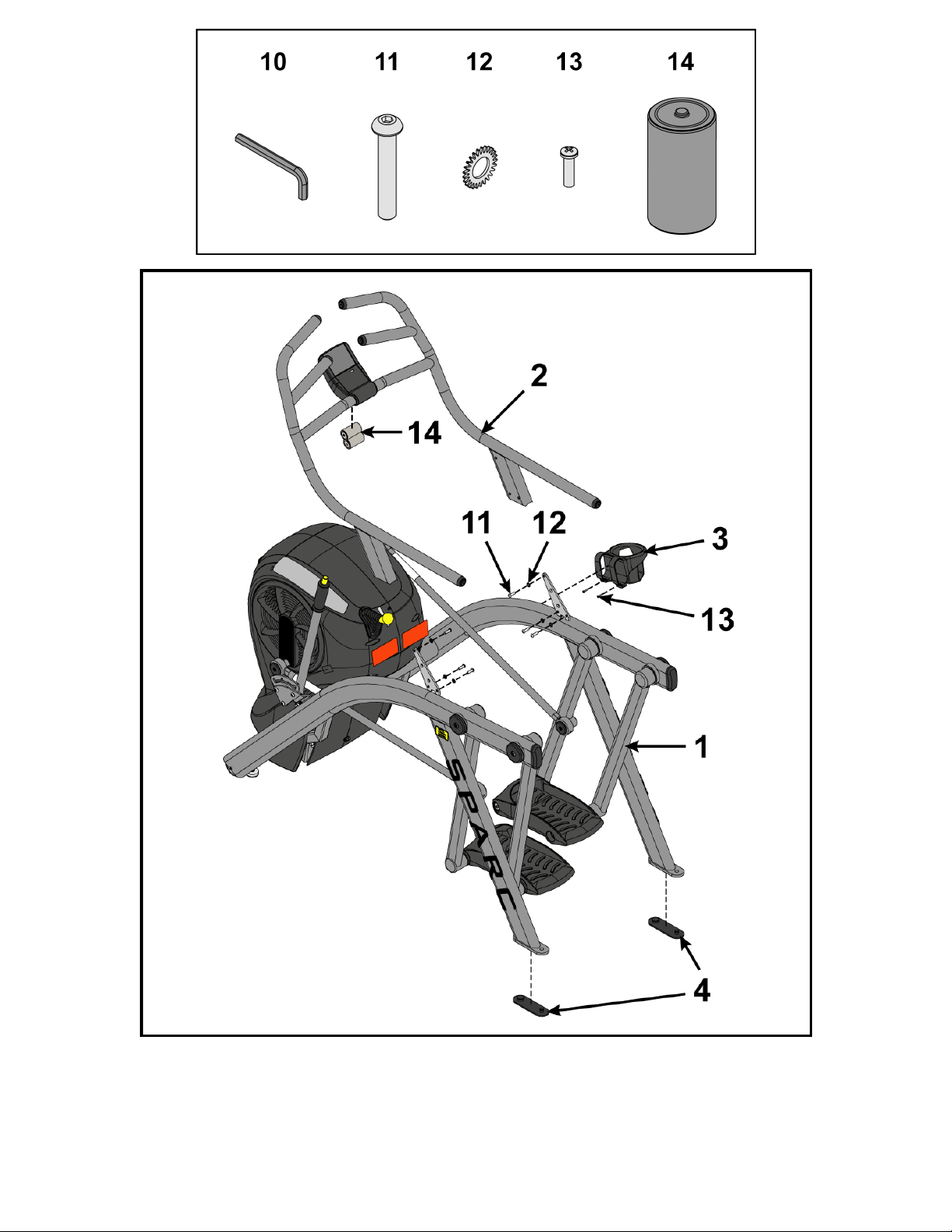
Hardware
Item Quantity Part Number Description
10 1 BK030201 3/16” Allen Wrench
11 6 HC660417 BHSCS .312-18 x 1”
12 6 HS327300 Lock washer, External Tooth .312
13 2 HT552515 Tap screw, 8-16 x .75"
14 2 EC-25295 Battery, D Cell 1.5V Alkaline 2 pack
Page 12 of 36
Li and Move Unit
1. Remove lag bolts and shipping supports. Keep package material on linkage arms at this time. This will protect the paint from
scratching during assembly.
2. Grasp each rear support leg firmly and li with one person on each side.
Page 13 of 36
3. Li the lower rear support legs so the front transport wheels are able to roll on floor.
Use proper liing methods.
4. Move unit to intended location.
5. Lower rear support legs.
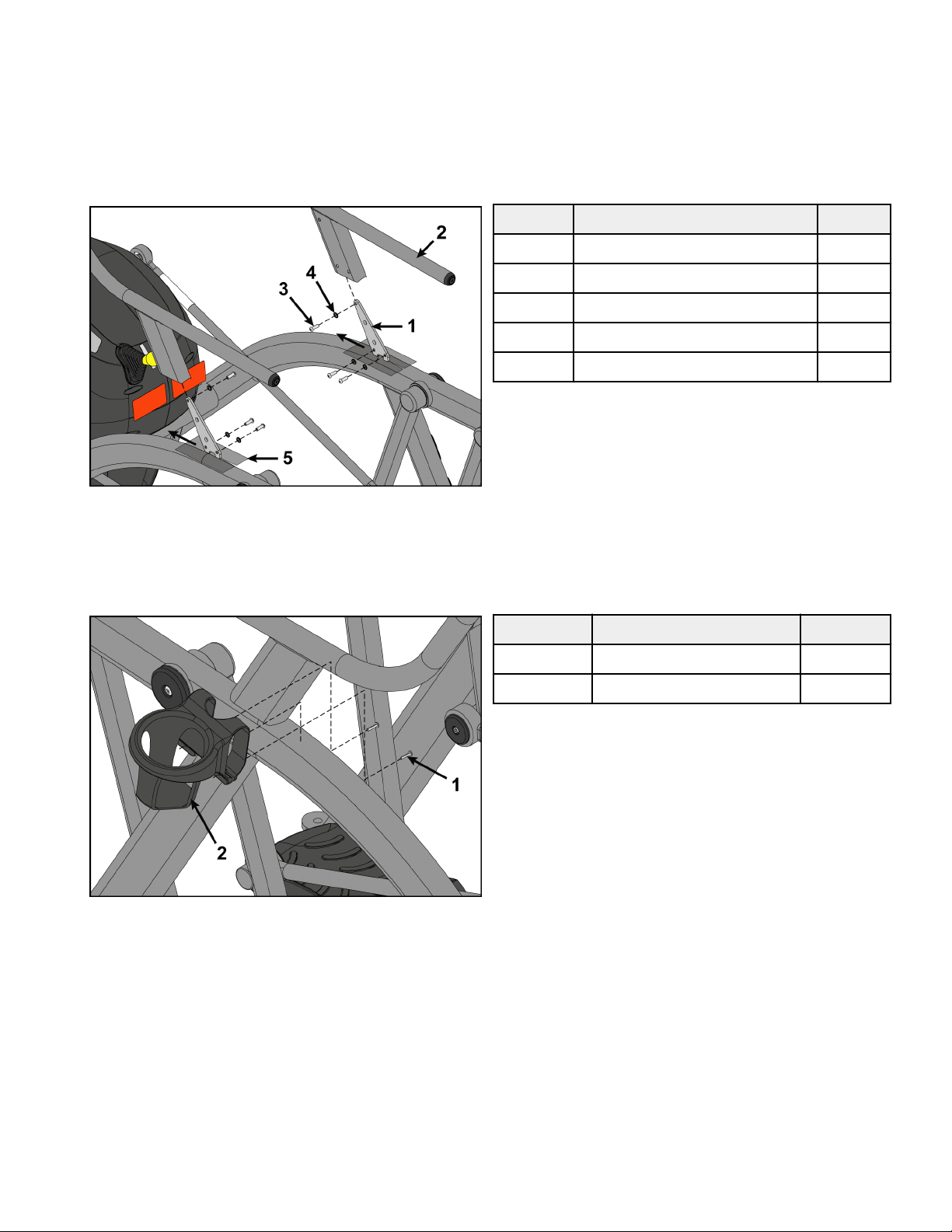
Install Handrail Assembly
1. Place handrail assembly into position on the base assembly.
Item Description Qty.
1 Base assembly 1
2 Handrail assembly 1
3 Screw 6
4 Lock washer 6
5 Plastic sheet 2
2. Install screws and lock washers securing handrail assembly to base assembly using a 3/16" Allen wrench.
3. Remove plastic sheet from base assembly.
4. Place cup holder onto base assembly.
5. Install screws securing cup holder to base assembly using a Phillips screwdriver.
Item Description Qty.
1 Screw 2
2 Cup holder 1
Page 14 of 36
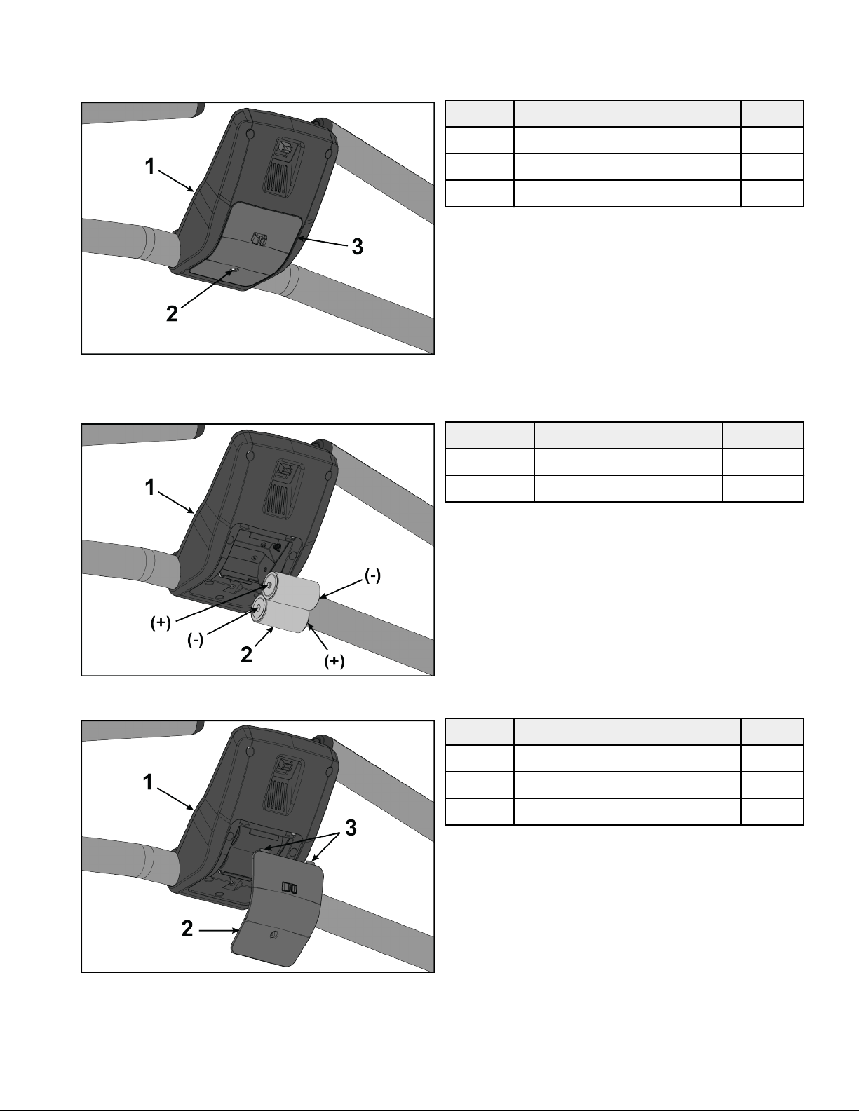
Install Batteries
1. Remove the battery access cover by loosening the screw using a flat head screwdriver. The screw will remain in the battery access
cover.
Item Description Qty.
1 Console 1
2 Screw 1
3 Battery access cover 1
2. NOTE: The batteries must be installed in the proper direction.
Install two batteries as shown.
Item Description Qty.
1 Console 1
2 Batteries 2
3. Insert the two battery access cover tabs into console.
Item Description Qty.
1 Console 1
2 Battery access cover 1
3 Tabs 2
4. Tighten the battery access cover screw using a flat head screwdriver.
Page 15 of 36
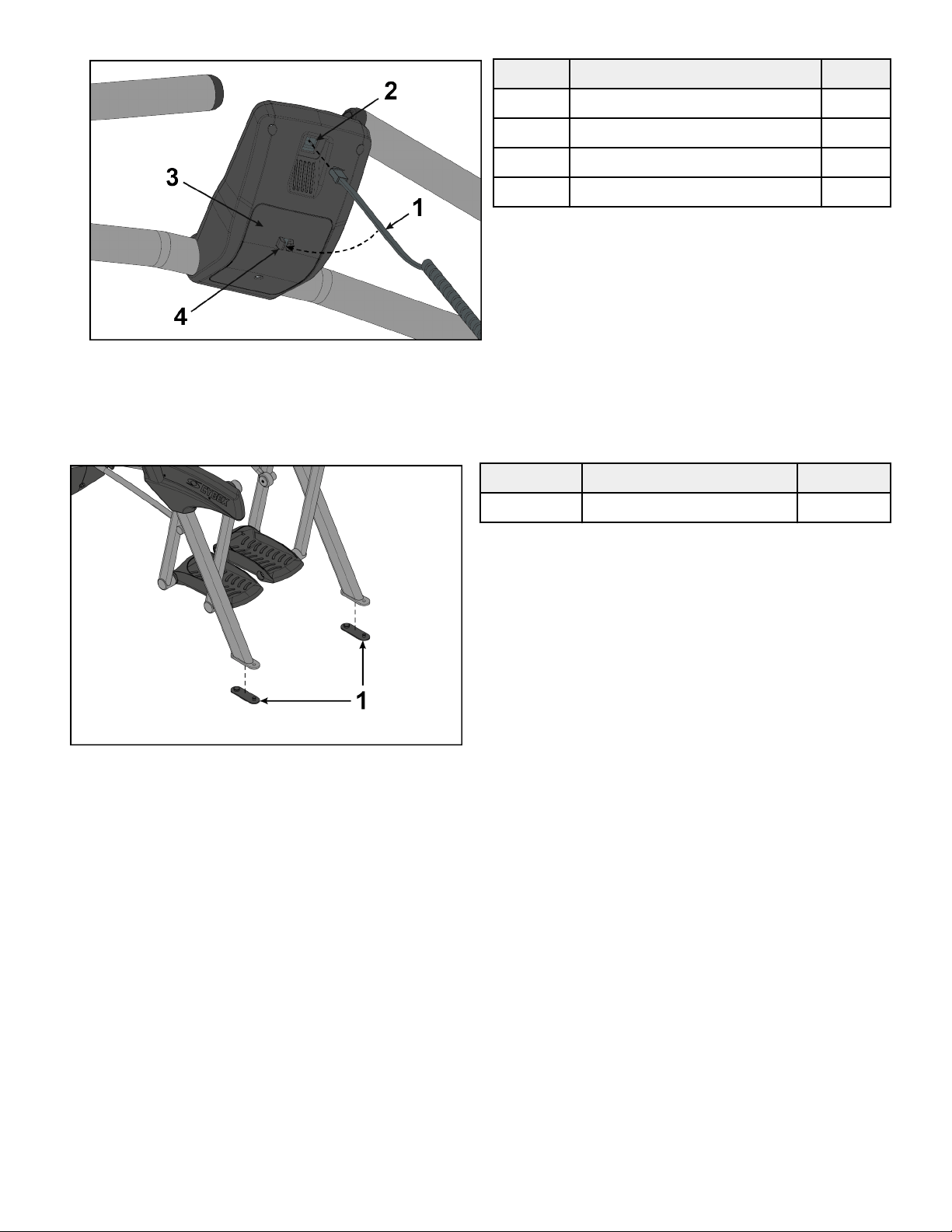
5. Plug the console cable from shroud into the console.
Item Description Qty.
1 Console cable 1
2 Console 1
3 Battery access cover 1
4 Mounting tabs 1
6. Insert the console cable into the mounting tabs on the battery access cover.
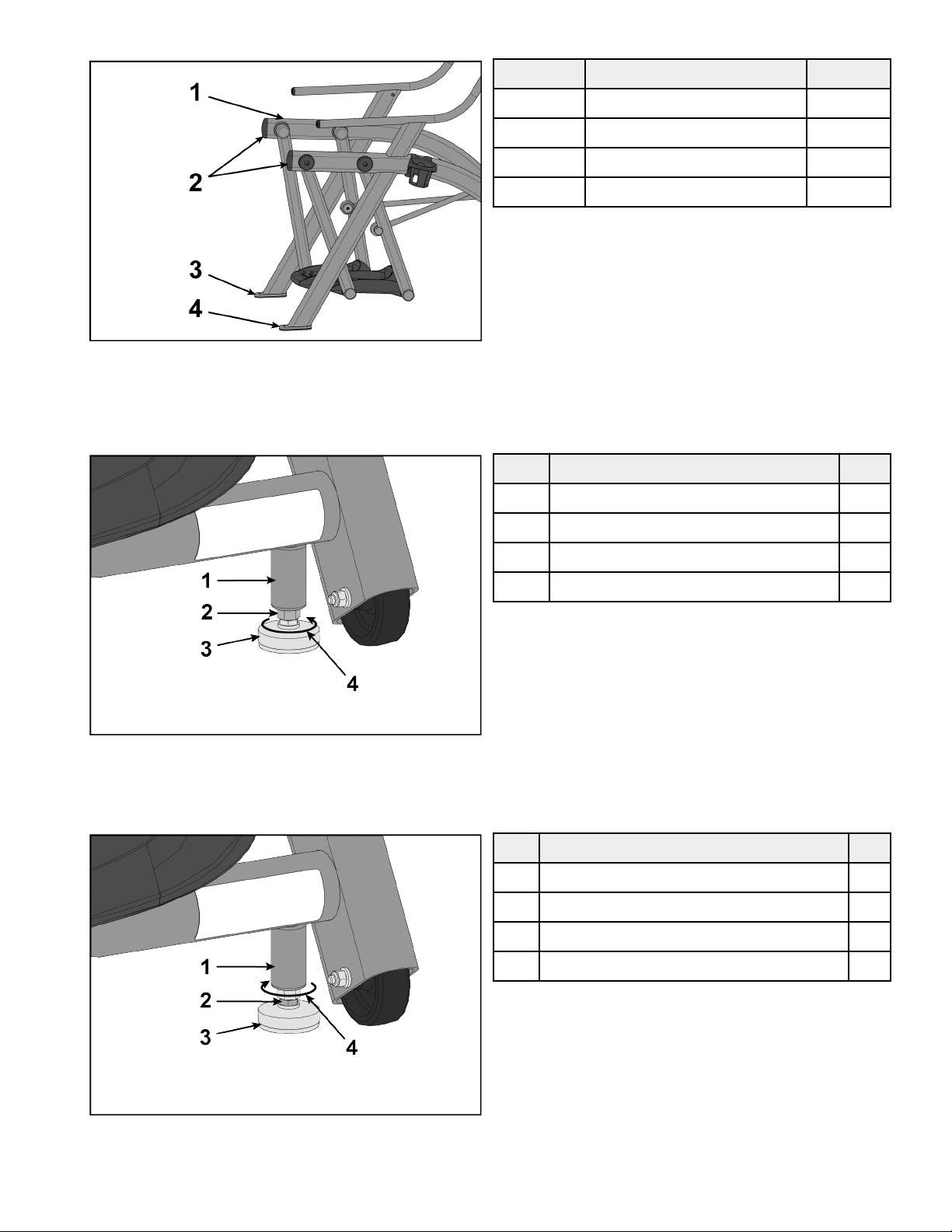
Install Foot Pads
Have one person li the unit while a second person places a foot pad under each of the two back feet.
Item Description Qty.
1 Foot pads 2
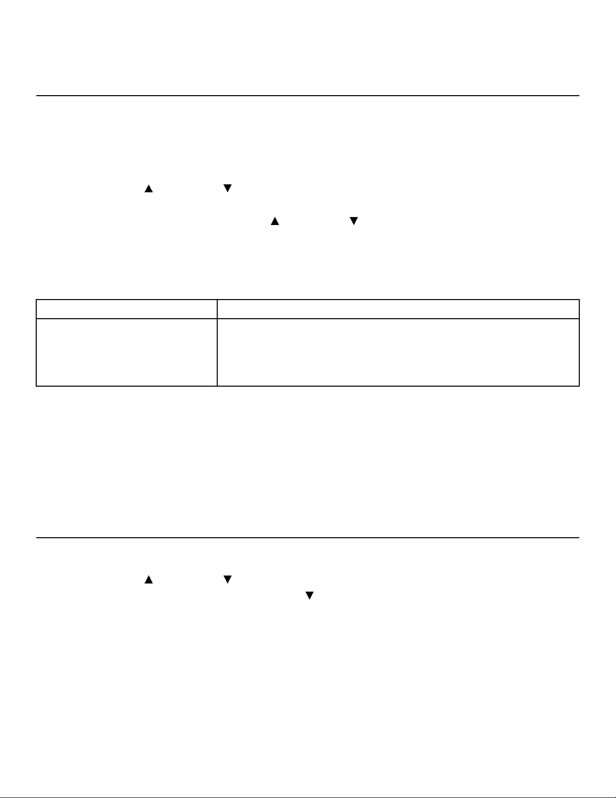
Level Unit
This procedure will level the unit by evenly adjusting the weight on the rear feet. Leveling the unit will eliminate rocking during use.
NOTE: References to le and right are from the users perspective during use.
1. Verify foot plates are completely stopped.
Page 16 of 36
2. Grasp one side of the frame and slowly li the rear foot o the floor. Lower rear foot to the floor.
Item Description Qty.
1 Frame 2
2 Li here 2
3 Le rear foot 1
4 Right rear foot 1
3. Grasp the other side of the frame and slowly li the rear foot o the floor. Lower rear foot to the floor.
Make note of either rear foot liing o the floor easier than the other.
If both rear feet li o the floor evenly, secure both leveling foot jam nuts against the frame post using a 9/16” open-end wrench.
Unit is leveled.
Item Description Qty.
1 Frame post 1
2 Jam nut 1
3 Leveling foot 1
4 Turn counter-clockwise to secure 1
4. Adjust the weight of the rear feet using a 1/2” open-end wrench.
• If the le rear foot lis up easier, Adjust the right leveling foot nut down.
• If the right rear foot lis up easier, Adjust the le leveling foot nut down.
Item Description Qty.
1 Frame post 1
2 Leveling foot nut 1
3 Leveling foot 1
4 Turn clockwise to adjust leveling foot down 1
5. Test the unit again for uneven weight on the rear feet. Adjust leveling foot nuts until each rear foot lis with even force.
6. Secure both jam nuts using a 9/16” open-end wrench. Unit is leveled.
Page 17 of 36
Visually Inspect Unit
1. Remove any packing material from unit.
2. Examine the unit to ensure that the assembly is correct and complete.
Setup
Use the following instructions to setup the unit.
1. Hold the handrails to steady self while stepping into the foot plates.
2. Begin striding.
Setup Options
1. Press and hold the Up arrow and Down arrow for 3 seconds.
2. Press the GO/Enter key.
3. Navigate up and down in the setup menu with the Up arrow and Down arrow.
4. Navigate forward in the setup menu with the GO/Enter key.
5. Navigate backward in the setup menu with the STOP/Review key.
Setup menu
LANGUAGE Choose from available languages
INTERVAL TRAINING
SET DEFAULT WORK: Set the default work interval. Choices are 10 to 180 in 10 second
increments.
SET DEFAULT REST: Set the default rest interval. Choices are 10 to 180 in 10 second
increments.
Exit Setup mode
1. Select BACK in the setup menu.
2. Press the GO/Enter key.
3. Select EXIT in the setup menu.
4. Press the GO/Enter key.
Setup Complete
Calibrate Resistance Level
Perform this calibration procedure to display the correct resistance levels throughout the full range of the resistance lever. This is
required when installing the unit, replacing the console or sensor board, or if the unit has been disassembled.
1. Press and hold the Up arrow and Down arrow for 3 seconds.
2. Navigate in the Toolbox menu to DIAGNOSTICS with the Down arrow.
Page 18 of 36
3. Press the GO/Enter key to enter DIAGNOSTICS.
4. Push the resistance lever forwards to the highest resistance level.
5. Press and hold the Up arrow for three seconds until the BRAKE VALUE section blinks. The upper value is stored.
6. Pull the resistance lever backwards to the lowest resistance level.
7. Press and hold the Down
arrow for three seconds until the BRAKE VALUE section blinks. The lower value is stored.
8. Press the GO/Enter key to go BACK to the toolbox menu.
9. Press the Down
arrow to select EXIT in the setup menu.
10. Press the GO/Enter key to exit Toolbox.
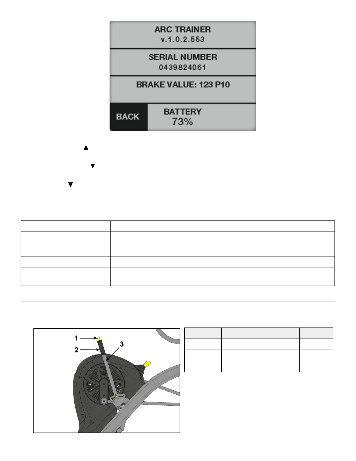
Diagnostics menu
ARC TRAINER Soware revision number.
PRESSURE/TEMP
Pressure: Displays Barometric pressure in HPA (hectopascal).
Temperature : Displays local temperature in degrees Celsius.
BRAKE VALUE Displays brake position value. Range is P1 to P10.
BATTERY Displays battery level from 0 to 100% in 10% increments. LOW BATTERY screen will be
displayed at 10%.
Testing Operation
Use the following instructions to test the full resistance and incline range of the unit:
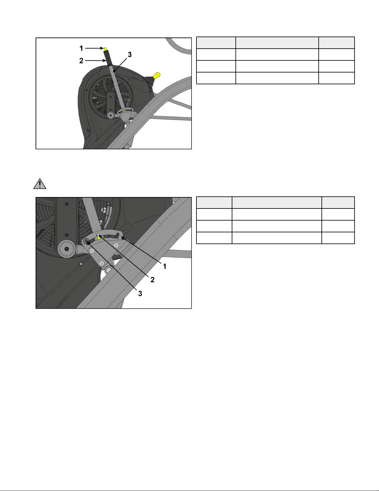
1. Grasp handle on incline lever and depress the plunger.
Item Description Qty.
1 Plunger 1
2 Handle 1
3 Incline lever 1
Page 19 of 36
2. Move incline lever to back position.
3. Release plunger on incline lever.
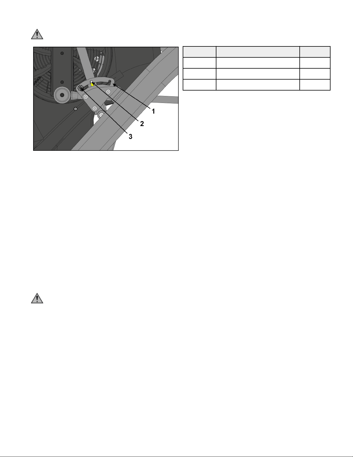
CAUTION: To avoid injury, be sure detent pin is fully inserted into notch in adjusting plate before use.
Item Description Qty.
1 Adjusting plate 1
2 Detent pin 1
3 Notch 3
4. Move the resistance lever down to lowest resistance.
5. Verify foot plates are completely stopped.
6. Hold the handrails to steady self while stepping into the foot plates.
7. Begin striding.
8. Verify the control panel will illuminate.
9. Press the GO/Enter key.
10. Verify level meter is at LEVEL 1 and resistance is low.
11. Verify WATTS are displayed on display screen.
12. Move the resistance lever up to LEVEL 5.
Verify resistance is higher than LEVEL 1.
13. Move the resistance lever up to LEVEL 10.
Verify resistance is higher than LEVEL 5.
14. Move the resistance lever down to LEVEL 1.
15. Press the STOP/Review key to exit.
16. Wait until foot plates come to a complete stop before dismounting unit.
WARNING: Moving parts and fall hazard.
• To avoid serious injury wait until foot plates come to a complete stop before getting o unit.
• The moving parts cannot be stopped immediately, the unit is not equipped with a free wheel.
Hold handrails to steady self while stepping o unit.
17. Move incline lever to middle position.
18. Move incline lever to forward position.
19. Move incline lever to back position.
Testing complete.
Page 20 of 36
Operation
Individual Human Power Versus Mechanical Power
WARNING: Power dierence.
The individual human power which is required to carry out an exercise can be dierent than the mechanical power displayed.
Intended Use
The intended commercial use of this machine is to aid exercise and improve general physical fitness.
Terms Used
This section lists some of the common terms and symbols used in this chapter. Other terms and symbols are listed in this chapter as
appropriate.
Circuit Circuit Mode functions as a count-up timer ideally suited for use within small group classes with multiple
users using the machine for short bouts. It may also be used like a Quick Start for longer duration training
sessions.
Interval Interval Mode allows the user to predefine the duration work and rest intervals as well as the total number
of sets to be performed.
Rest The period of an interval training session that is performed at a lower intensity to provide for recovery
aer the Work interval in an Interval Mode training session.
Results Review of the accumulated workout data will happen at the end of each workout session.
Sets The number of time a Work:Rest interval is to be performed.
Work The period of high intensity eort in an interval training session.
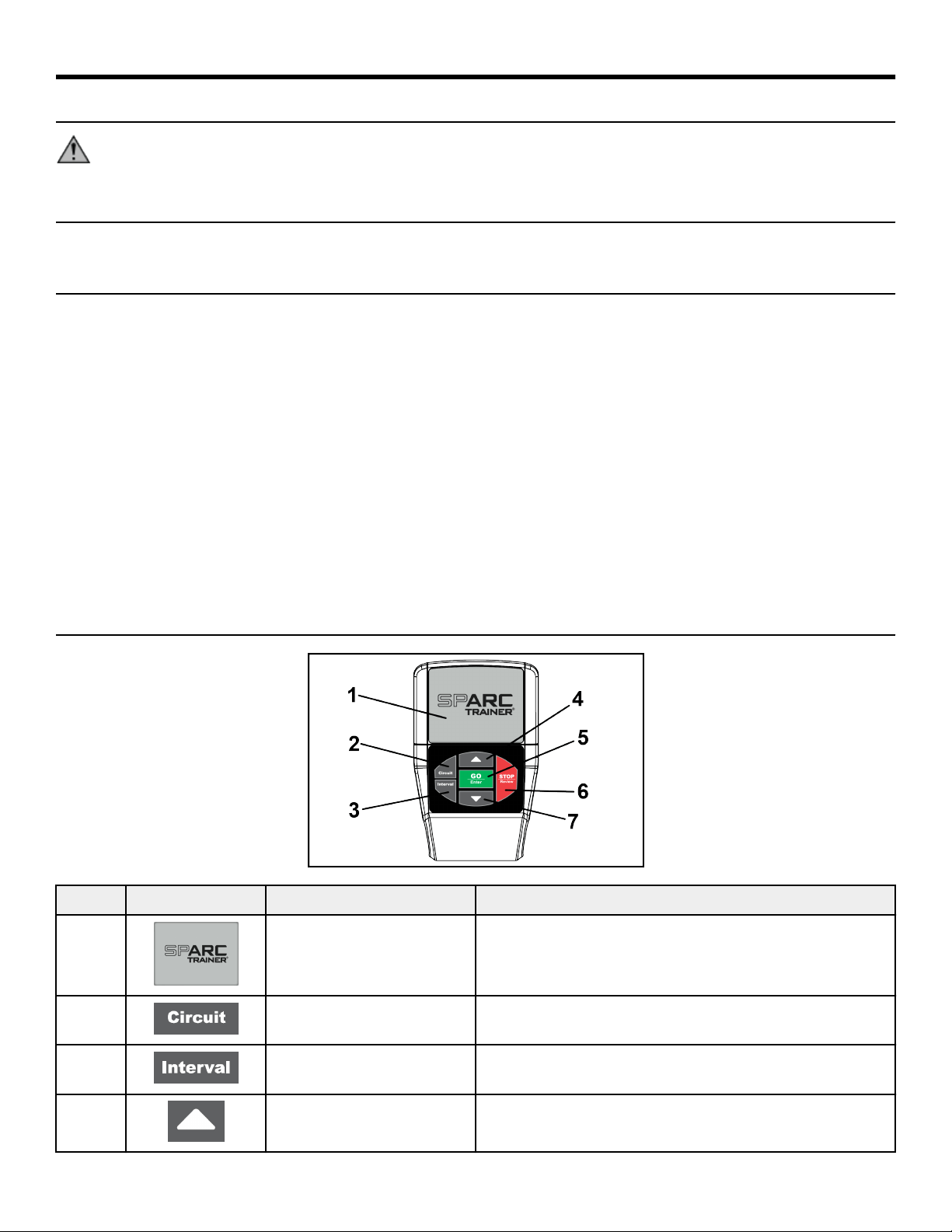
User Controls
Item Control Name Description
1 DISPLAY SCREEN Displays all information.
2 CIRCUIT KEY Selects Circuit workout.
3 INTERVAL KEY Selects Interval workout.
4 ARROW UP Adjust values up. Navigate up in menus, languages, defaults, and
other settings.
Page 21 of 36
Item Control Name Description
5 GO/ENTER KEY Start Circuit workout. Enter settings during Interval workout
setup. Select settings in Toolbox screen, moves forward in menu.
6 STOP/REVIEW KEY Ends a workout. Resets console. Navigates back in Setup menu.
7 ARROW DOWN Adjust values down. Navigate down in menus, languages,
defaults, and other settings.
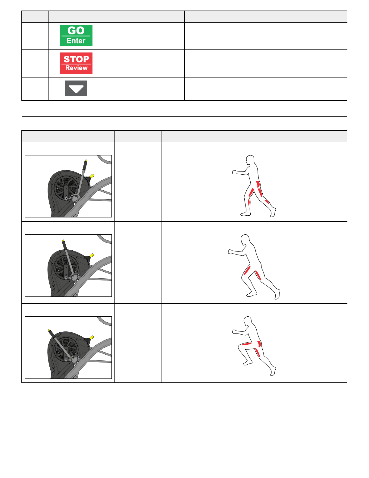
Incline Lever
Incline is set by adjusting the incline lever. There are three settings available. Set the Incline before your workout.
Setting Incline Muscles Used
Back 12.4% Glutes, Hamstrings, Calves
Middle 19.4% Quadriceps
Forward 25.5% Glutes, Quadriceps
Page 22 of 36
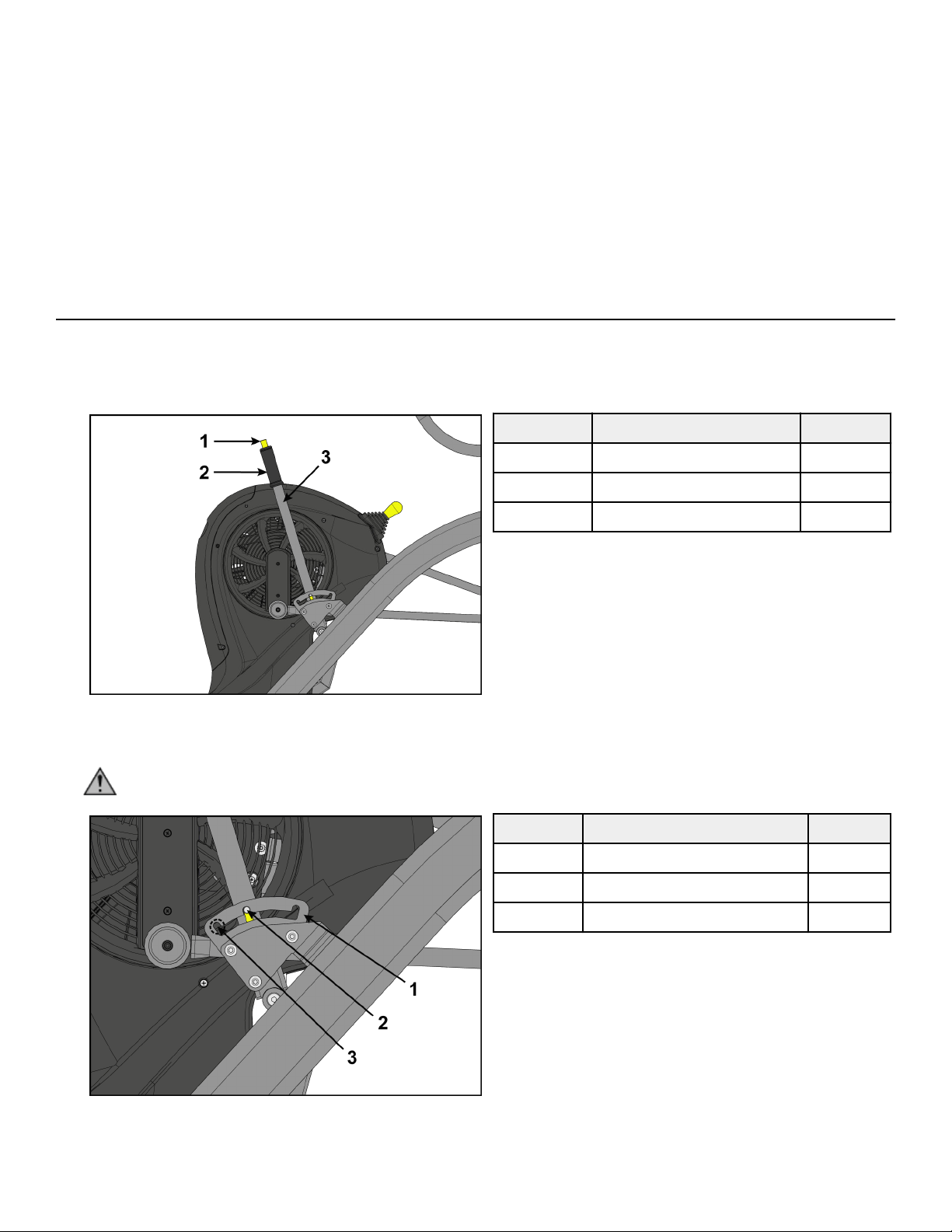
Adjust Incline Lever
1. Grasp handle on incline lever and depress the plunger.
Item Description Qty.
1 Plunger 1
2 Handle 1
3 Incline lever 1
2. Move incline lever to desired position.
3. Release plunger on incline lever.
CAUTION: To avoid injury, be sure detent pin is fully inserted into notch in adjusting plate before use.
Item Description Qty.
1 Adjusting plate 1
2 Detent pin 1
3 Notch 3
Page 23 of 36
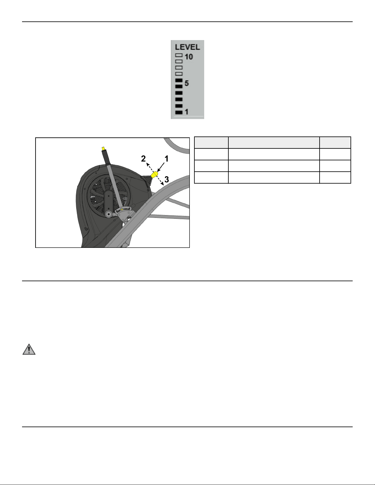
Resistance Lever
Resistance is changed using the resistance lever. Range is 1 to 10 in increments of 1. Changes to resistance are displayed on the display
screen with the LEVEL meter.
1. Pull the resistance lever backwards to decrease the resistance level.
Item Description Qty.
1 Resistance lever 1
2 Forward 1
3 Backward 1
2. Push the resistance lever forwards to increase the resistance level.
Mount and Dismount
Mount unit safely
1. Verify foot plates are completely stopped.
2. Grasp handrail and step carefully onto foot plates.
Dismount unit safely
WARNING: Moving parts and fall hazard.
• To avoid serious injury wait until foot plates come to a complete stop before getting o unit.
• The moving parts cannot be stopped immediately, the unit is not equipped with a free wheel.
1. Grasp handrails for support.
2. Stop striding.
3. Wait until foot plates come to a complete stop.
4. Continue to hold handrails while carefully stepping o unit.
Quick Operation Guide
Maximum user weight is 400 lbs. (181 kg).
The following is a quick overview of the operation of the unit.
1. Verify foot plates are completely stopped.
Page 24 of 36
2. Grasp handle on incline lever and depress the plunger.
3. Move incline lever to desired position.
4. Release plunger on incline lever.
5. Grasp handrail and step carefully onto foot plates.
Begin striding.
6. Press the Circuit key.
7. Press the GO/Enter key.
8. Adjust the resistance lever to change the resistance at any time. The level meter will display the current resistence level.
9. Press the STOP/Review key at any time to end workout.
Workout Results are displayed.
Detailed Operation Guide
Maximum user weight is 400 lbs. (181 kg).
1. Verify foot plates are completely stopped.
2. Grasp handle on incline lever and depress the plunger.
Item Description Qty.
1 Plunger 1
2 Handle 1
3 Incline lever 1
3. Move incline lever to desired position.
4. Release plunger on incline lever.
CAUTION: To avoid injury, be sure detent pin is fully inserted into notch in adjusting plate before use.
Item Description Qty.
1 Adjusting plate 1
2 Detent pin 1
3 Notch 3
5. Grasp handrail and step carefully onto foot plates.
Begin striding.
Page 25 of 36
6. Choose a Circuit or Interval workout.
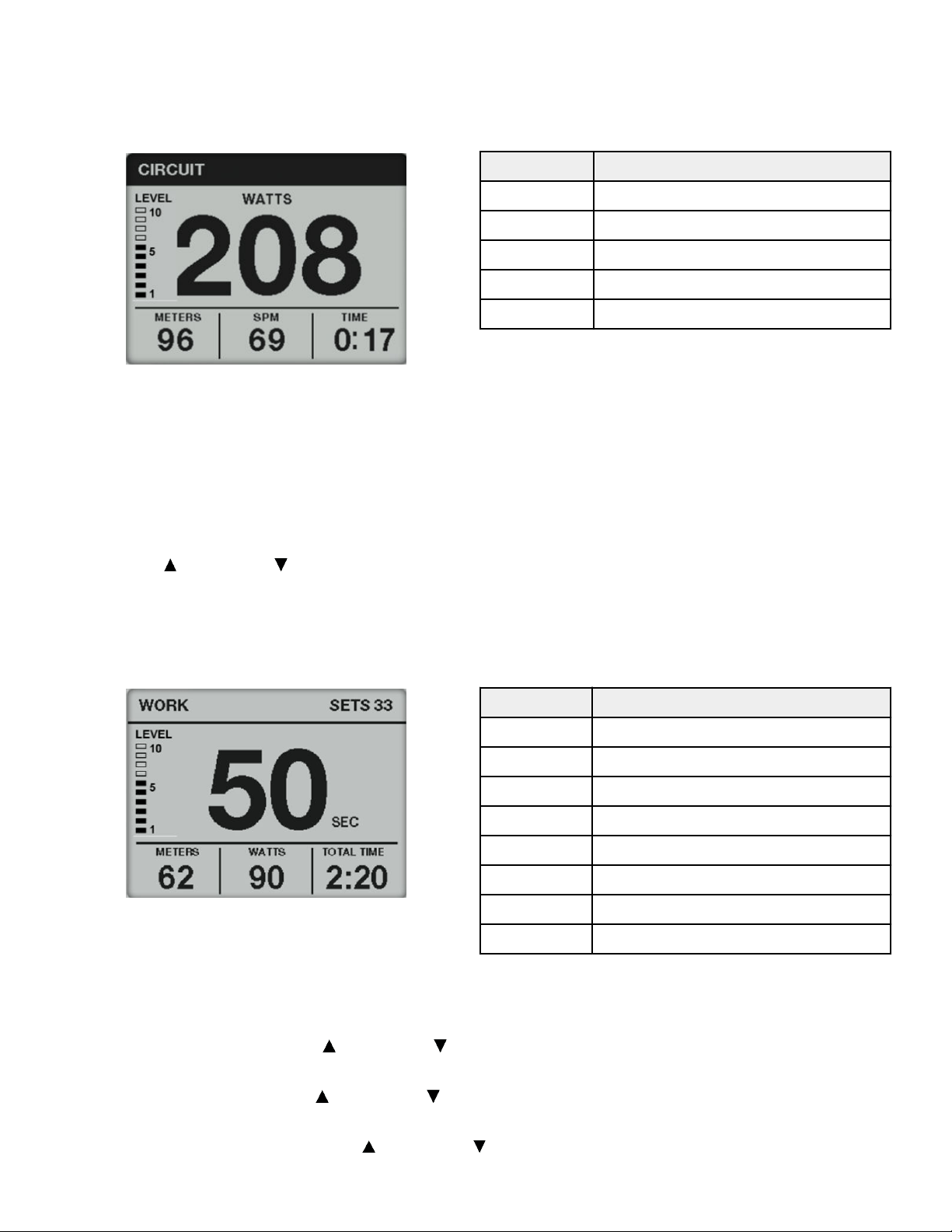
Circuit Workout Overview
Circuit Mode functions as a count-up timer ideally suited for use within small group classes with multiple users using the machine for
short bouts. It may also be used like a Quick Start for longer duration training sessions.
Display Description
LEVEL Displays current resistance level
WATTS Displays current watts
METERS/KM Displays total meters or kilometers
SPM Displays current Strides Per Minute
TIME Displays total time of workout
Circuit Workout
1. Press the Circuit key.
2. Press the GO/Enter key.
3. Adjust the resistance lever to change the resistance at any time. The level meter will display the current resistence level.
4. Press the STOP/Review key at any time to end workout.
Workout Results are displayed.
5. Press the Up arrow or Down arrow to review Results.
6. Press STOP/Review to exit workout.
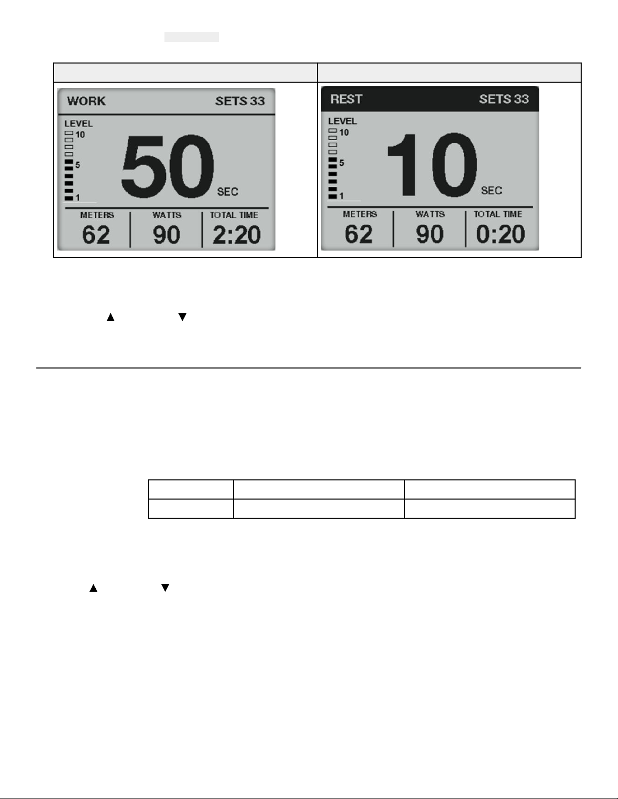
Interval Workout Overview
Interval Mode allows the user to predefine the duration work and rest intervals as well as the total number of sets to be performed.
Display Description
WORK Exercise during this interval
REST Rest during this interval
SETS Remaing number of sets in workout
LEVEL Displays current resistance level
SEC Countdown timer to next interval.
METERS/KM Displays total meters or kilometers
WATTS Displays current watts
TOTAL TIME Displays total time of workout
Interval Workout
1. Press the Interval key.
2. Adjust WORK TIME using the Up arrow
or Down arrow . Range is 10 to 180 in 10 second increments.
3. Press the GO/Enter key.
4. Adjust REST TIME using the Up arrow or Down arrow . Range is 10 to 180 in 10 second increments.
5. Press the GO/Enter key.
6. Adjust TOTAL INTERVALS using the Up arrow or Down arrow . Range is 1 to 30 in 1 interval increments.
TOTAL TIME of workout will be displayed.
Page 26 of 36
7. Press the GO/Enter key.
A three second countdown 3...2...1 is displayed. The Interval workout begins with the first WORK session.
8. Begin striding. The display screen will alternate between WORK and REST screens. Timer counts down to next interval.
Stride during WORK segment Rest during REST segment
9. Adjust the resistance lever to change the resistance at any time. The level meter will display the current resistence level.
10. Press the STOP/Review key at any time to end workout.
Workout Results are displayed.
11. Press the Up arrow or Down arrow to review Results.
12. Press the STOP/Review key.
Results
As the user exercises, the unit keeps track of and displays the following data:
PEAK WATTS Highest workload energy exertion.
AVG WATTS Average workload energy exertion.
AVG SPM (Strides per
Minute)
The average number of strides per minute.
TIME The total time you've been working out. Display time as minutes:seconds.
MM:SS Minutes:Seconds 00:01 to 99:99
MMMM Minutes 100 minutes or more
METERS/KM Total distance in Meters or Kilometers. Displays METERS up to 499 meters, then displays KM starting at 0.5
km.
CALORIES The total accumulated calories burned during your workout.
Press the Up arrow or Down arrow to review Results.
Page 27 of 36
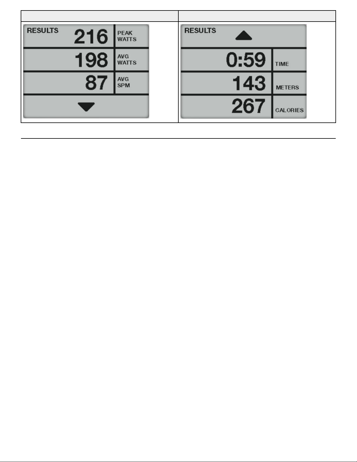
RESULTS screen 1 RESULTS screen 2
How power input versus displayed value is calculated
Total power, as displayed in Watts on the console, is calculated from the measured speed of the fan and the resistance provided by the
Eddy Current Brake. Variability of the fan power due to atmospheric conditions is compensated for by incorporating feedback from an
on-board barometric pressure and temperature sensors.
Page 28 of 36

Maintenance
All preventive maintenance activities must be performed on a regular basis. Performing routine preventive maintenance actions can
aid in providing safe, trouble-free operation of all Cybex equipment.
Cybex is not responsible for performing regular inspection and maintenance actions for your machines. Instruct all personnel in
equipment inspection and maintenance actions and also in accident reporting and recording. Cybex representatives are available to
answer any questions that you may have.
Warnings
TIP: Read all warnings in this chapter.
WARNING: For maintenance, service and repair:
• Must be performed by trained service personnel only
• Use only replacement parts
• Keep water and liquids away from electrical parts.
WARNING: Equipment hazard.
To avoid serious injury or death replace worn or damaged components immediately and keep the equipment out of use until
repair is completed.
Clean Unit
Tools Required
• Cleaning solution
• Rubbing alcohol
• Clean cloth
• Vacuum
Aer Each Use
Wipe up any liquid spills immediately. Aer each workout, use a cloth to wipe up any remaining perspiration from the handrails and
painted surfaces.
Be careful not to spill or get excessive moisture between the edge of the display panel and the console, as this might create an
electrical hazard or cause failure of the electronics.
As Needed
Vacuum any dust or dirt that might accumulate under or around the unit. Cleaning this area should be done as oen as indicated in
the Service Schedule.
Clean Console
NOTICE: Do not spray cleaning solution directly on the console.
Direct spraying could cause damage to the electronics and may void the warranty.
• Spray a mild cleaning agent on a clean cloth.
• Clean the console and cup holder with a damp cloth.
Clean Base
• Spray a mild cleaning agent on a clean cloth.
• Clean the base of the unit with a damp cloth.
Batteries
The console is powered with two, D cell, alkaline batteries.
If the battery level is 10% or lower, The console will display LOW BATTERY at start up.
Page 29 of 36

Replace the batteries if LOW BATTERY appears at start up,
Storage or long non-use periods
When not using product for more than six months, the batteries should be removed to prevent leakage.
Check battery level
The battery level can be checked through the console.
1. Press and hold the Up
arrow and Down arrow for 3 seconds.
2. Navigate in the Toolbox menu to DIAGNOSTICS with the Down arrow.
3. Press the GO/Enter key to enter DIAGNOSTICS.
1. The BATTERY level is displayed on the DIAGNOSTICS screen.
• Levels 20-100% - Batteries are good.
• Levels 0-10% - Batteries need to be replaced.
4. Press the GO/Enter key to go BACK to the toolbox menu.
5. Press the Down arrow to select EXIT in the setup menu.
6. Press the GO/Enter key to exit Toolbox.
Battery replacement
Replace batteries with two new, D cell, alkaline batteries. If replacement batteries are weak and have a battery level of 40% or lower,
the LOW BATTERY screen will continue to be displayed at start up.
NOTE: Do not use rechargeable batteries.
Tools required:
• Flat head screwdriver
NOTICE: Component damage.
Page 30 of 36
Replace with two, D cell, alkaline batteries only. Always use two new equal batteries, of the same current rating and manufacturer.
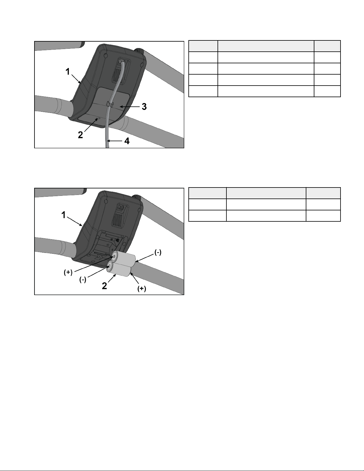
1. Remove the battery access cover by loosening the screw using a flat head screwdriver. The screw will remain in the battery access
cover.
Item Description Qty.
1 Console 1
2 Screw 1
3 Battery access cover 1
4 Console cable 1
• The battery access cover screw will remain in the battery access cover.
• The battery access cover will remain on the console cable.
2. Remove the two batteries from the console.
Item Description Qty.
1 Console 1
2 Batteries 2
3. NOTE: The batteries must be installed in the proper direction.
Install two, D cell, alkaline batteries as shown.
Page 31 of 36
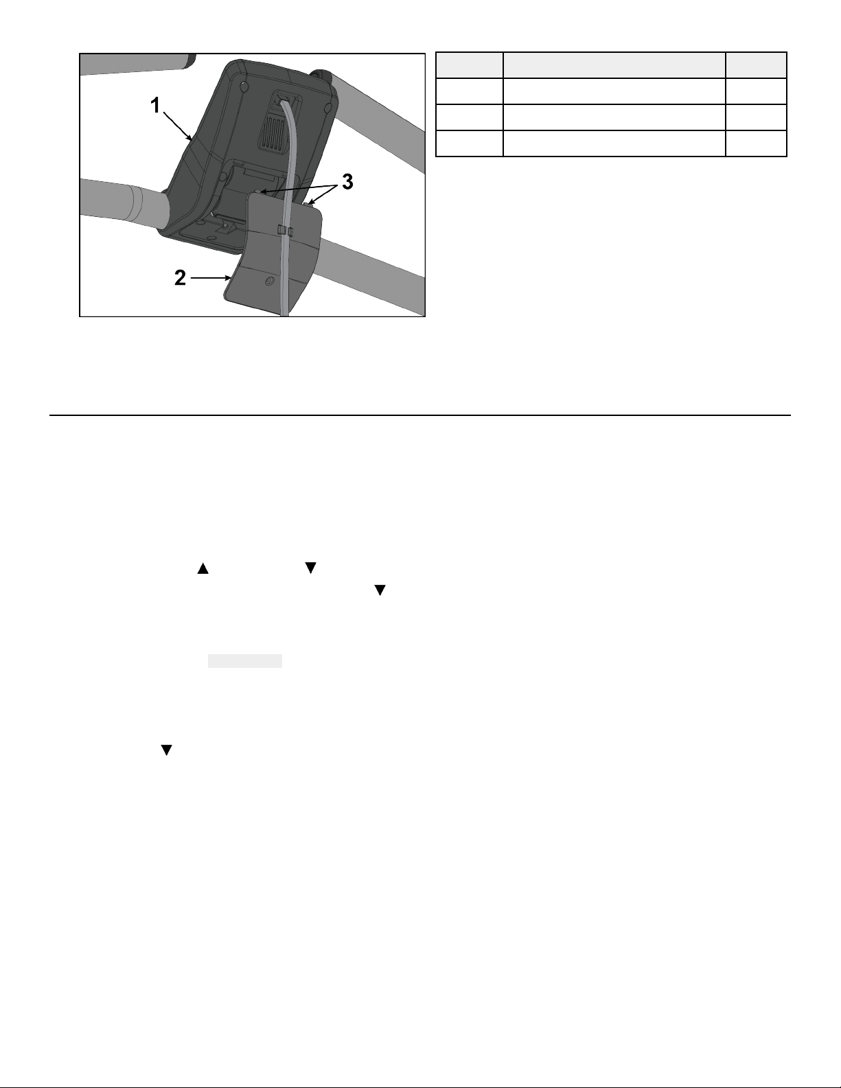
4. Insert the two battery access cover tabs into console.
Item Description Qty.
1 Console 1
2 Battery access cover 1
3 Tabs 2
5. Tighten the battery access cover screw using a flat head screwdriver.
NOTE: Dispose of batteries safely aer replacement or before unit disposal.
Service Schedule
All maintenance activities shall be performed by qualified personnel. Failure to do so could result in serious injury.
This is the minimum recommended service.
Determine distance
1. Verify foot plates are completely stopped.
2. Grasp handrail and step carefully onto foot plates.
3. Press and hold the Up arrow and Down arrow for 3 seconds.
4. Navigate in the Toolbox menu to STATS with the Down arrow.
5. Press the GO/Enter key to enter STATS.
1. The TOTAL ON TIME and TOTAL RUN TIME is displayed on the STATS screen.
The time is displayed as ###:##:## (Days:Hours:Minutes).
NOTE: A Day is recorded as 24 hours of use. It is not days used or days since installation.
6. Record the TOTAL RUN TIME.
7. Press the GO/Enter key to go BACK to the toolbox menu.
8. Press the Down
arrow to select EXIT in the setup menu.
9. Press the GO/Enter key to exit Toolbox.
Daily Procedures
See detailed procedures in Clean Unit section.
1. Clean console
2. Clean base.
Every 6 Months
The TOTAL RUN TIME for 6 months is approximately 6 days.
1. Move unit and vacuum underneath. Li the rear of unit and roll it back from its present position. Vacuum underneath and return
unit to normal position.
2. Check battery level.
Page 32 of 36

Every 12 Months
The TOTAL RUN TIME for 12 months is approximately 12 days.
Contact qualified service technician to perform the following procedures.
1. Inspect incline assembly.
2. Replace any worn parts.
3. Lubricate incline bushings.
Page 33 of 36

Customer Service
Product Registration
To register product do the following:.
1. Visit www.cybexintl.com.
2. Locate Product Registration in the Support section.
3. Fill out form completely.
4. Click the Submit button to register product.
Contacting Service
Hours of phone service are Monday through Friday from 8:30 a.m. to 6:00 p.m. Eastern Standard Time.
For Cybex customers living in the USA, contact Cybex Customer Service at 1-888-462-9239.
For Cybex customers living outside the USA, contact Cybex Customer Service at 1-508-533-4300 or fax 1-508-533-5183. Email address
Find information on the web at www.cybexintl.com.
To contact us online go to www.cybexintl.com.
Ordering Parts
To order parts online go to www.cybexintl.com.
To speak with a customer service representative, call 800-351-3737 (for customers living within the USA) or 847-288-3700 (for
customers outside the USA).
The following information located on the serial number decal will assist our Cybex representatives in serving you.
• Unit Serial Number, Product Name and Model Number
• Part Description and Part Number if you have it. All parts can be found on the web at www.cybexintl.com
• Shipping Address
• Contact Name
• Include a description of the problem.
In addition to your shipping address and contact name, your account number is helpful but not required. You may also fax orders to
800-216-8893.
Return Material Authorization (RMA)
The Return Material Authorization (RMA) system is used when returning material for placement, repair or credit. The system assures
that returned materials are properly handled and analyzed. Follow the following procedures carefully.
Contact your authorized Cybex dealer on all warranty-related matters. Your local Cybex dealer will request a RMA from Cybex, if
applicable. Under no circumstances will defective parts or equipment be accepted by Cybex without proper RMA and an Automated
Return Service (ARS) label.
Please contact Cybex Customer Service for the return of any item that is defective.
Provide the technician with a detailed description of the problem you are having or the defect in the item you wish to return. Provide
the model and serial number of your Cybex equipment.
At Cybex’s discretion, the technician may request that you return the problem part(s) to Cybex for evaluation and repair or
replacement. The technician will assign you a RMA number and will send you an ARS label. The ARS label and the RMA numbers must
be clearly displayed on the outside of the package that contains the item(s) to be returned. Include the description of the problem, the
serial number of the equipment and the name and address of the owner in the package along with the part(s).
Merchandise returned without an RMA number on the outside of the package or shipments sent COD will not be accepted by the
Cybex receiving department.
Page 34 of 36

Damaged Parts
Materials damaged in shipment should not be returned for credit. Shipping damages are the responsibility of the carrier (UPS, Federal
Express, trucking companies, etc.)
Apparent Damage
Upon receipt of your shipment, check all items carefully. Any damage seen with a visual check must be noted on the freight bill and
signed by the carrier’s agent. Failure to do so will result in the carriers refusal to honor your damage claim. The carrier will provide you
with the required forms for filing such claims.
Concealed Damage
Damage not seen with a visual check upon receipt of a shipment but notices later must be reported to the carrier as soon as possible.
Upon discovery of the damage, a written or phone request to the carrier asking them to perform an inspection of the materials must
be made within ten days of the delivery date. Keep all shipping containers and packing materials as they will be needed in the
inspection process. The carrier will provide you with an inspection report and the necessary forms for filing a concealed damage claim.
Concealed damage claim is the carrier’s responsibility.
Page 35 of 36

Columbia Center III - 9525 Bryn Mawr Ave, Rosemont, IL 60018 • 800-351-3737 • 847-288-3700 • FAX 800-216-8893
www.cybexintl.com