

Cybex Arc Trainer
®
Owners Manual and Service Manual
Cardiovascular Systems
Part Number 5750-4 G
www.cybexintl.com

Cybex® and the
Cybex logo are registered trademarks of Cybex International, Inc.
Polar
®
is a registered trademark of Polar Electro Inc.
iPOD
®
is registered trademark of Apple.
DISCLAIMER: Cybex International, Inc., makes no representations or warranties regarding the
contents of this manual. We reserve the right to revise this document at any time or to make
changes to the product described within it without notice or obligation to notify any person of such
revisions or changes.
© Copyright 2011, Cybex International, Inc. All rights reserved. Printed in the United States of
America.
10 Trotter Drive Medway, MA 02053 • 508-533-4300 • FAX 508-533-5183
FCC Compliance Information
...........3
Safety
Ground and Voltage Information ........4
Important Safety Instructions ...........5
Warning and Caution Decals ...........7
CSAFE Port
.......................10
Assembly and Set Up
Warning and Caution Decals .......... 11
Choosing and Preparing Site.......... 11
Electrical Power Requirements ........ 11
Technical Specications - 750A ........12
750A Top View .....................13
750AT Top View ....................13
Technical Specications - 750AT .......14
Tools Required.....................15
750A Contents .....................15
750A Hardware Pack ................17
750AT Contents ....................18
750AT Hardware Pack ...............19
Testing Operation...................33
Setup Screen ......................34
Preventive Maintenance
Warnings .........................65
Cleaning Unit ...................... 65
Preventive Maintenance Activities ......66
Remove Access Cover...............66
Attach Access Cover ................67
Drive Belts . . . . . . . . . . . . . . . . . . . . . . . . 67
Recommended Service Schedule . . . . . . 68
Statistics..........................69
Error Codes . . . . . . . . . . . . . . . . . . . . . . . 70
Rechargeable Battery ...............71
Environment.......................71
Customer Service
Product Registration ................72
Contacting Service..................72
Serial Number .....................73
Ordering Parts . . . . . . . . . . . . . . . . . . . . . 74
Servicing of Double-Insulated Products..74
Return Material Authorization (RMA) ....74
Damaged Parts ....................75
Table of Contents

Cybex Arc Trainer 750A/750AT Owner’s Manual
3
FCC Compliance Information
WARNING: Changes or modications to this unit not expressly approved by the party
responsible for compliance could void the user’s authority to operate the
equipment!
This equipment has been tested and found to comply with the limits for a Class B digital device,
pursuant to Part 15 of the FCC Rules. These limits are designed to provide reasonable protection
against harmful interference in a residential installation.
This equipment generates, uses and can radiate radio frequency energy and (if not installed and used
in accordance with the instructions) may cause harmful interference to radio
communications. There is no guarantee that interference will not occur in a particular
installation.
If equipment does cause harmful interference to radio or television reception, (determine by turning
the equipment off and on) the user is encouraged to try to correct the interference by one or more of
the following methods:
Reorient or relocate the receiving antenna.•
Increase the separation between the equipment and receiver.•
Connect the equipment into an outlet on a different circuit from the receiver.•
Consult dealer or an experienced radio/TV technician.•
Cybex Arc Trainer 750A/750AT Owner’s Manual
4
Safety
IMPORTANT: Read all instructions and warnings before using.
Ground and Voltage Information
DANGER: Improper connection of equipment grounding conductor can result in a risk of
electric shock. Check with a qualied electrician or service provider if in doubt
as to whether the unit is properly grounded.
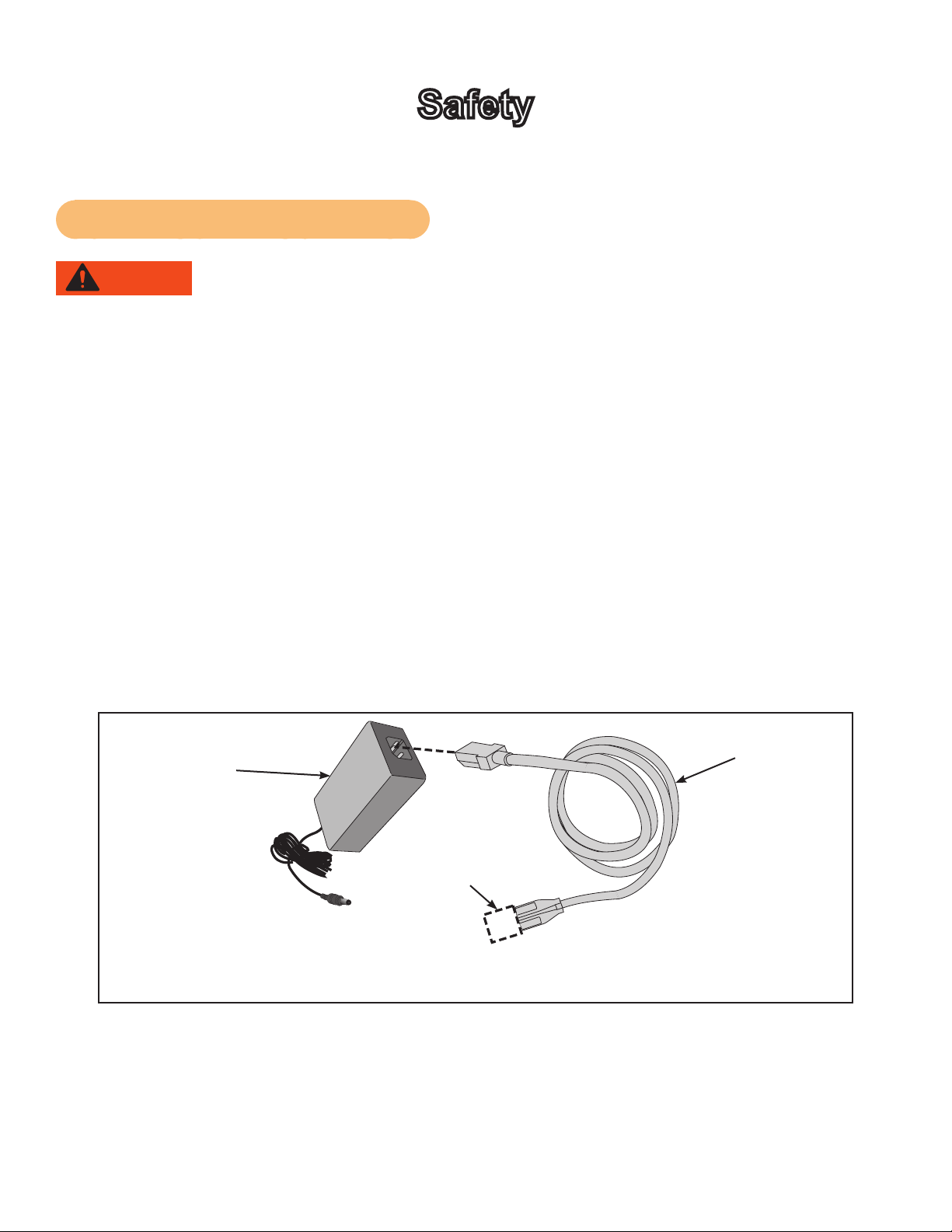
For Optional Power Supply
Unit must be grounded. This unit is equipped with an optional equipment-grounding conductor•
cord and a grounding plug.
Do not use a ground plug adapter to adapt the power cord to a non-grounded outlet.•
Plug must be plugged into an appropriate outlet that is properly installed and grounded in accor-•
dance with all local codes and ordinances.
If unit malfunctions, grounding provides path of least resistance for electric current to reduce risk•
of electric shock.
Cybexisnotresponsibleforinjuriesordamagesasaresultofcordorplugmodication.
Verify voltage requirements of unit match local voltage requirements.•
Verify unit outlet is the same conguration as the plug.•
Power
Adapter 24
VDC
Power Cord
NOTE: Use Cybex supplied power adapter and power cords only.
Connector
Varies by
Country

Cybex Arc Trainer 750A/750AT Owner’s Manual
5
Important Safety Instructions
(Save These Instructions)
DANGER: To reduce the risk of electrical shock, always unplug unit from electrical outlet
immediately after use and before cleaning.
WARNING: Serious injury could occur if these listed precautions are not observed.
Follow precautions to reduce the risk of burns, res, electric shock or injury.
User Safety Precautions
Obtain medical exam before beginning any exercise program.
• WARNING: Heart rate monitoring systems may be inaccurate. Over exercise may result in serious
injury or death. If you feel faint stop exercising immediately.
Stop exercising if feeling faint, dizzy or experiencing pain and consult your physician.
•
Obtain instruction before using. • Lisez les instructions avant l’utilisation.
• Read and understand the Owner’s Manual and all warnings posted on the unit before using.
Keep children away. Teenagers and disabled must be supervised. • Tenez les enfants éloignés. Les
adolescents et les handicapés doevent être surveilles.
Use the handrails for support and to maintain balance.•
Wait until foot plates come to a complete stop before dismounting. • Attendre l’arret complet des
reposes pieds avant de descendre.
Keep foot plate surface clean and dry.•
DO NOT• wear loose or dangling clothing while using.
Keep all body parts and other items free and clear of moving parts.•
DO NOT• use unit if user weight exceeds 400 lbs (180 kg). This is the rated maximum user weight.
Report any malfunctions, damage or repairs to the facility.•
Replace any warning labels if damaged, worn or illegible.•

Cybex Arc Trainer 750A/750AT Owner’s Manual
6
Facility Safety Precautions
NOTE: It is the sole responsibility of the user/owner or facility operator to ensure that regular
maintenance is performed.
Enforce all user and safety precautions.•
Read and understand the Owner’s Manual completely before assembling, servicing or using unit.•
Verify all users are properly trained on using the equipment.•
Do not use unit outdoors.•
Verify that each unit is setup, leveled and operated on a solid, level surface. Do not install•
equipment on an uneven surface.
Verify there is enough room for safe access and operation of unit.•
Use Cybex AC power adapters only.•
Do not use the optional power adapter in damp or wet locations.•
Do not use the unit if: (1) the unit is plugged into an optional power adapter that has a damaged•
cord; (2) the unit is not working properly or (3) if the unit has been dropped or damaged. Seek ser-
vice from a qualied technician.
EQUIPMENT is not suitable for use in the presence of aerosol (spray), FLAMMABLE•
ANAESTHETIC MIXTURE WITH AIR or WITH OXYGEN or NITROUS OXIDE.
Perform regular maintenance checks on unit. Performance level can be maintained only if•
examined regularly. Pay close attention to all areas most susceptible to wear, including (but not
limited to) cables, pulleys, belts and grips.
Replace any warning labels if damaged, worn or illegible.•
Immediately replace worn or damaged components. If unable to immediately replace worn or•
damaged components, then remove unit from service until repair is made.
Do not attempt repairs; electrical or mechanical. Seek qualied repair technician when servicing.•
Failure to do so could result in serious injury. Customer Service for contact information.
Use only Cybex supplied components to maintain/repair unit.•
Keep a repair log of all maintenance activities.•
Disconnect the optional power adapter before servicing unit.•
Do not use attachments unless recommended for the unit by Cybex.•
The unit may generate electromagnetic or other forms of interference, or it may be affected by•
interference from other equipment nearby. If this is suspected, take precautions by separating the
equipment or otherwise shielding it to avoid such interference.
Cybex Arc Trainer 750A/750AT Owner’s Manual
7
Unit with A/V Options
Devices connected to Cybex equipment must comply with appropriate safety standards. This includes
but not limited to: UL 1647 and EN 60335-1.
There must be adequate mechanical mounting of the device in all combinations (congurations).
Device must be stable on the unit in all congurations.
Warning and Caution Decals
NOTE: To replace any worn or damaged labels, Customer Service for contact information.
Warning decals indicate a potentially hazardous situation which, if not avoided, could result in death
or serious injury.
Carefully read and understand the following caution and warning labels before using the unit.
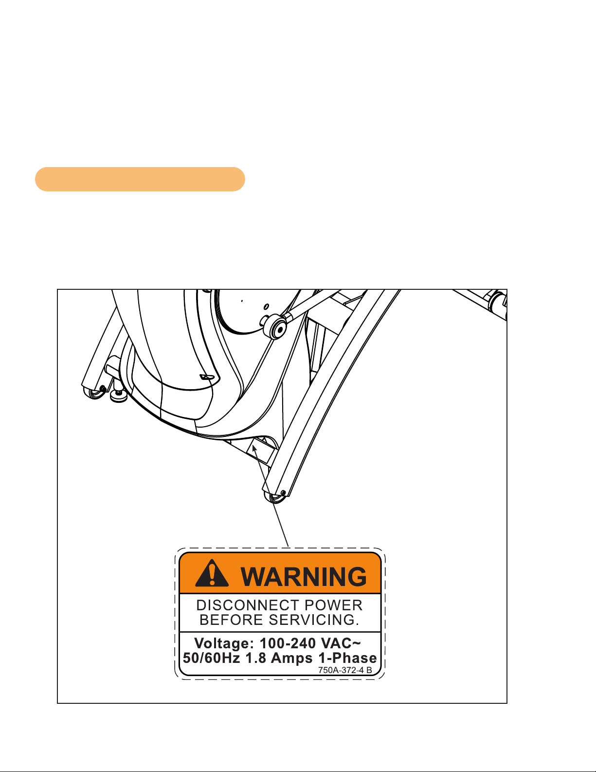
Warning decal part number
750A-372-4 (if applicable)
DECAL, DISCONNECT POWER
ENGLISH
REL
7-24-08
750A-372-4
125
1:1
OWATONNA
MFG. APPR.
TECH. PUBS. APPR. DATE
DATE
REV.
DWG. NO.
SCALE
SIZE
CHECKED BY
DWG. BY
TITLE:
FINISH:
MATERIAL:
B
SHEET
OF
EXCEPT AS NOTED
GENERAL
TOLERANCES:
2 DECIMALS ± .03
3 DECIMALS ± .015
ANGLES ± 1°
FEATURES SHOWN
PERPENDICULAR OR
PARALLEL SHALL BE
SO WITHIN ± 1°
REMOVE ALL BURRS
BREAK SHARP EDGES
.005/.010 R
SURFACE FINISH
INDICATED PER
ANSI B46.1-1985
GENERAL
MACHINING
DIMENSIONS
IN INCHES
DATE
DATE
REMOVE CARBURIZATION
AND SCALE FROM LASER
AND PLASMA CUT EDGES
ALL MATERIAL MUST COMPLY TO
EUROPEAN UNION DIRECTIVE
2002/95/EC RoHS (RESTRICTION
OF HAZARDOUS SUBSTANCES)
1 1
B
NOTE: SEE ENGINEERING DRAWING 750A-372-X FOR SPECIFICATIONS.
BB
8-13-08
EML
8-13-08
750A-372-4 B
WARNING
DISCONNECT POWER
BEFORE SERVICING.
Voltage: 100-240 VAC~
50/60Hz 1.8 Amps 1-Phase
2.00
1.25
R .10
4 PLACES
SAFETY ORANGE PMS 152
BLACK TRIANGLE W/ ORANGE
EXCLAMATION POINT, BLACK LETTERS
18 PT ARIAL BOLD FONT
PART NUMBER
6 PT ARIAL TEXT
WHITE BACKGROUND WITH
BLACK 10 PT ARIAL TEXT
WHITE BACKGROUND WITH
BLACK 10 PT ARIAL BOLD TEXT
Cybex Arc Trainer 750A/750AT Owner’s Manual
8
125
1:1
OWATONNA
MFG. APPR.
TECH. PUBS. APPR. DATE
DATE
REV.
DWG. NO.
SCALE
SIZE
CHECKED BY
DWG. BY
TITLE:
FINISH:
MATERIAL:
B
SHEET
OF
EXCEPT AS NOTED
GENERAL
TOLERANCES:
2 DECIMALS ± .03
3 DECIMALS ± .015
ANGLES ± 1°
FEATURES SHOWN
PERPENDICULAR OR
PARALLEL SHALL BE
SO WITHIN ± 1°
REMOVE ALL BURRS
BREAK SHARP EDGES
.005/.010 R
SURFACE FINISH
INDICATED PER
ANSI B46.1-1985
GENERAL
MACHINING
DIMENSIONS
IN INCHES
DATE
DATE
REMOVE CARBURIZATION
AND SCALE FROM LASER
AND PLASMA CUT EDGES
ALL MATERIAL MUST COMPLY TO
EUROPEAN UNION DIRECTIVE
2002/95/EC RoHS (RESTRICTION
OF HAZARDOUS SUBSTANCES)
DECAL, CAUTION MOVING PARTS
DE-17219-4
B
1 1
JT
7-22-03
1.80
1.25
R .12
4 PLACES
SAFETY YELLOW PMS 108
BACKGROUND BLACK TRIANGLE
W/ YELLOW EXCLAMATION POINT,
BLACK LETTERS 18.9 PT ARIAL BLACK FONT
WHITE BACKGROUND WITH
BLACK 12 PT ARIAL TEXT
PART NUMBER
6.5 PT ARIAL TEXT
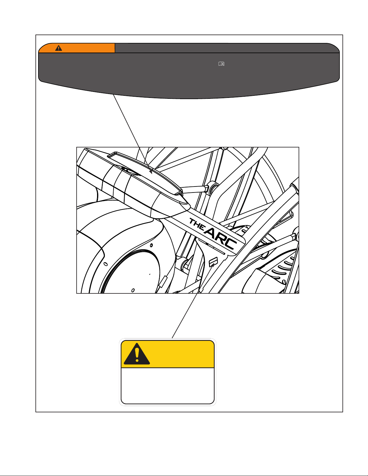
DE-17219-4 B
CAUTION
Moving parts.
Keep hands away
when in use.
DE-17219-4 B
CAUTION
Moving parts.
Keep hands away
when in use.
(SPECS)
MASTER
ARTWORK
DE-17219-4 A
CAUTION
Moving parts.
Keep hands away
when in use.
Warning decal part
number DE-17219-4
(Both Sides)
125
1:1
OWATONNA
MFG. APPR.
TECH. PUBS. APPR. D A T E
D A T E
REV.
DWG. NO.
SCALE
SIZE
CHECKED BY
DWG. BY
TITLE:
FINISH:
MATERIAL:
B
SHEET
OF
EXCEPT AS NOTED
GENERAL
TOLERANCES:
2 DECIMALS ± .03
3 DECIMALS ± .015
ANGLES ± 1°
FEATURES SHOWN
PERPENDICULAR OR
PARALLEL SHALL BE
SO WITHIN ± 1°
REMOVE ALL BURRS
BREAK SHARP EDGES
.005/.010 R
SURFACE FINISH
INDICATED PER
ANSI B46.1-1985
GENERAL
MACHINING
DIMENSIONS
IN INCHES
D A T E
D A T E
REMOVE CARBURIZATION
AND SCALE FROM LASER
AND PLASMA CUT EDGES
ALL MATERIAL MUST COMPLY TO
EUROPEAN UNION DIRECTIVE
2002/95/EC RoHS (RESTRICTION
OF HAZARDOUS SUBSTANCES)
750A-330-4
WARNING LABEL, CONSOLE
ENGLISH
REL
5-22-08
1 1
_
BB
5-22-08
NOTE:
1. SEE ENGINEERING DRAWING 750A-330-X FOR SPECIFICATIONS.
SERIOUS INJURY COULD OCCUR IF THESE PRECAUTIONS ARE NOT OBSERVED
750A-330-4
WARNING
1. Obtain a medical exam before beginning any exercise program.
2. WARNING! Heart rate monitoring systems may be inaccurate.
Over exercise may result in serious injury or death. If you feel
faint stop exercising immediately.
3. Stop exercising if feeling faint, dizzy, or experiencing pain and
consult your physician.
4. Obtain instruction before using. Lisez les instructions avant l'utilisation.
5. Read and understand the Owner's Manual and all warnings
posted on the unit before using.
6. Keep children away. Teenagers and disabled must be supervised.
Tenez les enfants éloignés. Les adolescents et les handicapés
doivent être surveilles.
7. Use the handrails for support and to maintain balance.
8. Wait until foot plates come to a complete stop before dismounting.
Attendre l'arret complet des reposes pieds avant de descendre.
9. Keep foot plate surface clean and dry.
10. DO NOT wear loose or dangling clothing while using.
11. Keep all body parts and other items free and clear of moving parts.
12. DO NOT use unit if user exceeds 400 lbs. (180 kg). This is the rated
maximum user weight.
13. Report any malfunctions, damage or repairs to the facility.
14. Replace any warning labels if damaged, worn or illegible.
Warning decal part
number 750A-330-4
Cybex Arc Trainer 750A/750AT Owner’s Manual
9
125
1:1
OWATONNA
MFG. APPR.
TECH. PUBS. APPR. DATE
DATE
REV.
DWG. NO.
SCALE
SIZE
CHECKED BY
DWG. BY
TITLE:
FINISH:
MATERIAL:
B
SHEET
OF
EXCEPT AS NOTED
GENERAL
TOLERANCES:
2 DECIMALS ± .03
3 DECIMALS ± .015
ANGLES ± 1°
FEATURES SHOWN
PERPENDICULAR OR
PARALLEL SHALL BE
SO WITHIN ± 1°
REMOVE ALL BURRS
BREAK SHARP EDGES
.005/.010 R
SURFACE FINISH
INDICATED PER
ANSI B46.1-1985
GENERAL
MACHINING
DIMENSIONS
IN INCHES
DATE
DATE
REMOVE CARBURIZATION
AND SCALE FROM LASER
AND PLASMA CUT EDGES
ALL MATERIAL MUST COMPLY TO
EUROPEAN UNION DIRECTIVE
2002/95/EC RoHS (RESTRICTION
OF HAZARDOUS SUBSTANCES)
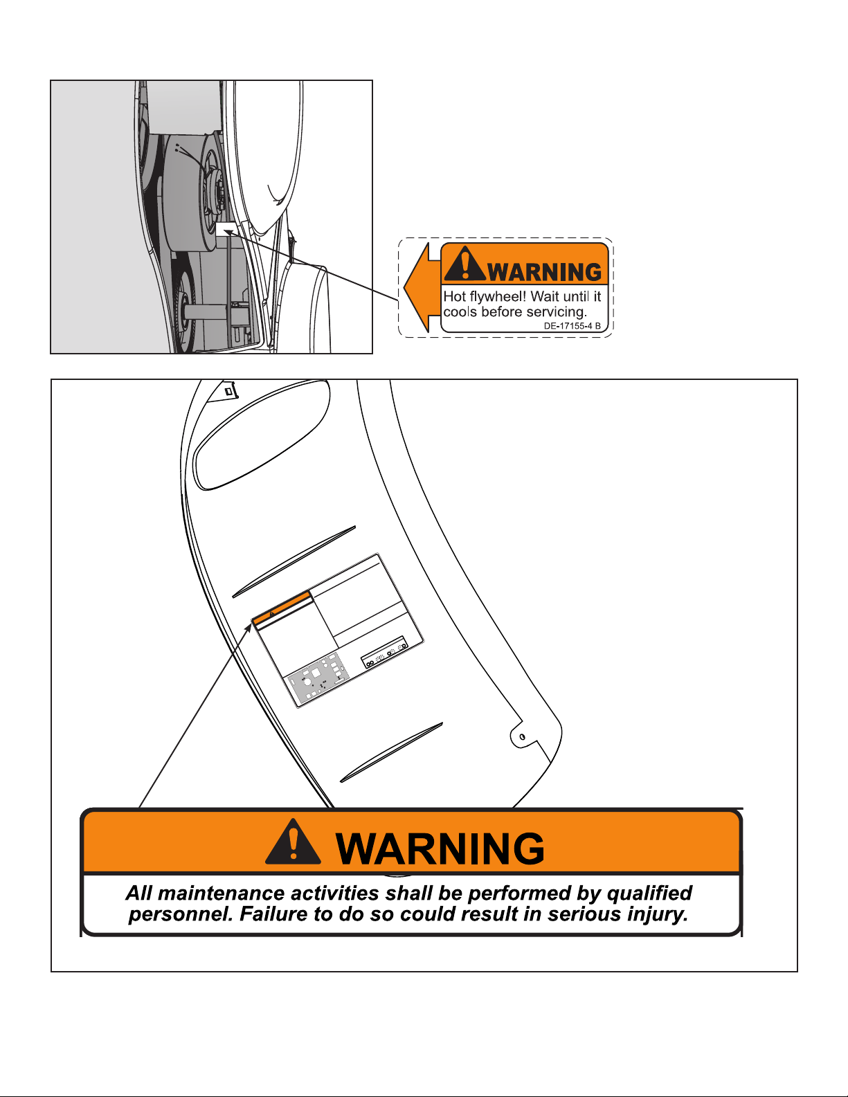
DE-17155-4
DECAL, WARNING
ENGLISH
1 1
B
JT
7-22-03
WARNING
DE-17155-4 B
Hot flywheel! Wait until it
cools before servicing.
SAFETY ORANGE PMS 152
BLACK TRIANGLE W/ ORANGE
EXCLAMATION POINT, BLACK LETTERS
17.54 PT ARIAL BLACK FONT
WHITE BACKGROUND WITH
BLACK 10.5 PT ARIAL TEXT
PART NUMBER
6.5 PT ARIAL TEXT
Warning decal part
number DE-17155-4
NOTE: This is the minimum recommended service.
NOTE:
If using optional AC Power Kit, unplug unit from wall outlet.
Determine mileage.
1.Start
pedaling unit.
2.During initial countdown, press CLEAR 9,9,9 ENTER.
The firstmenu item is ODOMETER. Press ENTER
to view accumulated distance.
First 500 Miles / 800 Km
A Check drive belts for tension and wear.
Every 5000 Miles / 8000 Km
A Check drive belts for tension and wear.
B Move unit and vacuum underneath.
C Remove access cover to clean inside - u
Every 20,000 Miles / 32000 Km
D Check elevation assembly and replace worn p
Service Schedule
U6
Q1
L3
T1
C25
J2
J1
J5
J4
D2
D36
C23
C24
K1
K2
K3
J8
J6
L5
10
9
3
4
2
1
7
8
6
5
LED 1 - Console Transmit
LED 2 - Console Receive
LED 3 - Battery Charge Status
LED 4 - Battery Charge Status
LED 5 - Powered from Generator
LED 6 - Brake Current
LED 7 - +12V External Power
LED 8 - Display Voltage (+12V)
LED 9 - Elevation Motor Down
LED 10 - Elevation Motor Up
Diagnostic LED Designation
All maintenance activities shall be performed by qualified
personnel. Failure to do so could result in serious injury.
NOTE: Refer to Service Manual for detailed trouble shooting information.
Set up (CLEAR 7,5,0, ENTER)
Diagnostic (CLEAR 8,8,8, ENTER)
Statistics (CLEAR 9,9,9, ENTER)
Entering Hidden Menus
A.Clean Brake/Enclosure
B.Check Connections
C.Check Fuse
D.Check Battery
750A-329-4
8Approaching Over-Temperature
9Display watchdog triggered B,H,K
22Speed irregularity - Low speed and High power
23Speed irregularity - High speed and Low power
24Incline moving too slowly D,F,J
25Incline movement feedback stopped
26Incline disabled C,D,E,F,J
27Low Battery B,G,I,K
28Over-Temperature A,B,C,G
29Controller watchdog triggered - EEPROM or Memory Error
Error Codes
BATTERY STATUS FROM LEDs 4 AND 3
NO
BATTERY
PRE
CHARGE
HIGH
CHARGE
TRICKLE
CHARGE
4
3
4
3
4
3
4
3
Warning decal part number - 750A-329-4
125
1:1
OWATONNA
MFG. APPR.
TECH. PUBS. APPR. DATE
DATE
REV.
DWG. NO.
SCALE
SIZE
CHECKED BY
DWG. BY
TITLE:
FINISH:
MATERIAL:
B
SHEET
OF
1 1
EXCEPT AS NOTED
GENERAL
TOLERANCES:
2 DECIMALS ± .03
3 DECIMALS ± .015
ANGLES ± 1°
FEATURES SHOWN
PERPENDICULAR OR
PARALLEL SHALL BE
SO WITHIN ± 1°
REMOVE ALL BURRS
BREAK SHARP EDGES
.005/.010 R
SURFACE FINISH
INDICATED PER
ANSI B46.1-1985
GENERAL
MACHINING
DIMENSIONS
IN INCHES
DATE
DATE
REMOVE CARBURIZATION
AND SCALE FROM LASER
AND PLASMA CUT EDGES
REL
7-18-08
A
750A-329-4
DECAL,WARNING & ERROR CODE
EML
7-30-08
BB
7-30-08
ALL MATERIAL MUST COMPLY TO
EUROPEAN UNION DIRECTIVE
2002/95/EC RoHS (RESTRICTION
OF HAZARDOUS SUBSTANCES)
BACKGROUND 30% GRAYSCALE
SAFETY ORANGE PMS 152
BLACK TRIANGLE W/ORANGE
EXCLAMATATION POINT
BLACK LETTERS 21 PT ARIAL
BOLD FONT
PART NUMBER
7 PT ARIAL TEXT
WHITE BACKGROUND
WITH BLACK 10 PT
ARIAL TEXT
7.00
10.00
R .10
BLUE PMS 2925
U6
Q1
L3
T1
C25
J2
J1
J5
J4
D2
D36
C23
C24
K1
K2
K3
J8
J6
L5
10
9
3
4
2
1
7
8
6
5
NOTE: Decal on inside of cover.
Cybex Arc Trainer 750A/750AT Owner’s Manual
10
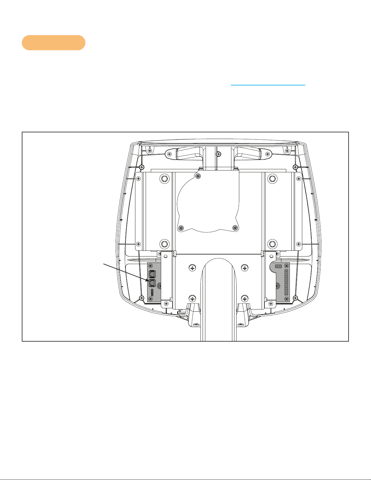
CSAFE Port
The CSAFE standard denes a communication protocol and low-voltage DC power source specic
to the Fitness Equipment Industry. These RJ-45 phone jacks are provided for use ONLY within the
CSAFE protocol. For more information on CSAFE standard, visit www.tlinxx.com/csafe.
NOTE: The CSAFE port inside the console, accessible through the back cover, is the only port that
carries BOTH the CSAFE communication lines and the 8.0v DC CSAFE power supply. If
attaching a CSAFE compliant device that requires power, this connection must be used.
Power is present only when the unit is in use or when a power supply is attached.
J7
J5
J9
J10
J8
CSAFE Port (J9)
Communication
8V DC/100 MA Power
Supply
Back of Console

Cybex Arc Trainer 750A/750AT Owner’s Manual
11
Assembly and Set Up
Warning and Caution Decals
Read and understand all warnings and cautions listed in
Safety Section
before assembling unit.
Use extreme caution when assembling the unit. Failure to do so could result in injury or death.
WARNING: Always use proper lifting methods when moving heavy items.
Ensure all electrical requirements are met as indicated in the specications in the
Safety Section
and
as listed in this chapter.
Choosing and Preparing Site
Before assembling the unit, verify chosen site meets the following criteria:
Area is well lit and well ventilated.
Surface is structurally sound and properly leveled.
NOTE: Place a 3/4” (1.9 cm) thick wood base under unit to protect carpeting.
Area allows for ample access and passage clearance around unit or for emergency dismount.
Minimum clearance is 19.7 inches (.5 meters) on at least one side of unit and also behind unit.
Electrical Power Requirements
NOTE: The AC power kit is optional.
Verify unit is connected to an outlet having the same conguration as the plug
Verify connection is a grounded circuit.
NOTE: Do not use a ground-plug adapter to adapt the 3-prong power cord to a non-grounded
electrical outlet.
NOTE: Use Cybex supplied optional AC power kit only. Consult an electrician with any questions.
Verify power supply is compliant with local building codes.

Cybex Arc Trainer 750A/750AT Owner’s Manual
12
Technical Specifications - 750A
Classification S (Studio)
Accuracy A
Assembled
Length
76.25” (194 cm)
Assembled
Width
31” (79 cm)
Height: 39.79” (101 cm)
Weight of
Product
404 lbs (183 kg)
Shipping
Weight
429 lbs (195 kg)
Incline Levels 0-20
Resistance
Levels
101 (Represented by 0-100% in increments of 1).
Stride Length 24” (61 cm) xed length.
Programs
Quick Start plus Manual, 8 Factory Programs, Heartrate Control, Constant Power,
Power Training, Fitness Test, and ability to store 9 custom programs.
Console
Features
Upper console: Large Bar Graph Matrix for displaying program proles, 16
character dot matrix area for display and scrolling text, a multi-color backlit heart
for conveying heartrate range. The Text Display area can show Cal/Hr, Distance,
Strides per Minute, Calories, Watts, METs and BPM.
Lower Console: Two numeric displays for incline, time, resistance and level.
Heart Rate
Features
Built-in wireless heart rate receiver (transmitter not included) and contact heart rate
monitoring.
Frame Colors
Standard: White texture, black texture, metaltone gold, black chrome, platinum
sparkle.
Custom: Unlimited colors available.
Resistance
Range
0-900 watt.
Maximum
User Weight
400 lbs. (181 kg).
Power Rating Self powered or 100 - 240 VAC~, 50/60 Hz, 1.8A, 1-phase.
Options Cybex Personal Entertainment Module and optional AC Power Adapter
Cybex Arc Trainer 750A/750AT Owner’s Manual
13
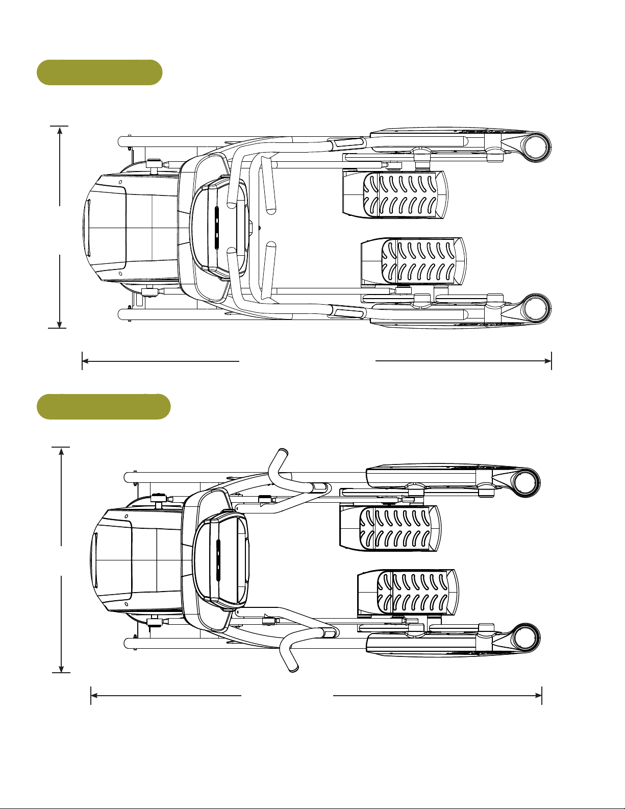
750A Top View
31”
(79 cm)
76.25” (194 cm)
750AT Top View
36.28”
(92 cm)
76.25” (194 cm)

Cybex Arc Trainer 750A/750AT Owner’s Manual
14
Technical Specifications - 750AT
Classification S (Studio)
Accuracy A
Assembled
Length
76.25” (194 cm)
Assembled
Width
36.28” (92cm)
Height: 62.5”(159 cm)
Weight of
Product
412 lbs. (187 kg.)
Shipping
Weight
437 lbs. (198 kg.)
Incline Levels 0-20
Resistance
Levels
101 (Represented by 0-100% in increments of 1).
Stride Length 24” (61 cm) xed length.
Programs
Quick Start plus Manual, 8 Factory Programs, Heartrate Control, Constant Power,
Power Training, Fitness Test, and ability to store 9 custom programs.
Console
Features
Upper console: Large Bar Graph Matrix for displaying program proles, 16
character dot matrix area for display and scrolling text, a multi-color backlit heart
for conveying heartrate range. The Text Display area can show Cal/Hr, Distance,
Strides per Minute, Calories, Watts, METs and BPM.
Lower Console: Two numeric displays for incline, time, resistance and level.
Heart Rate
Features
Built-in wireless heart rate receiver (transmitter not included) and contact heart rate
monitoring.
Frame Colors
Standard: White texture, black texture, metaltone gold, black chrome, platinum
sparkle.
Custom: Unlimited colors available.
Resistance
Range
0-900 watt.
Maximum
User Weight
400 lbs. (181 kg).
Power Rating Self powered or 100 - 240 VAC~, 50/60 Hz, 1.8A, 1-phase.
Options Cybex Personal Entertainment Module and optional AC Power Adapter

Cybex Arc Trainer 750A/750AT Owner’s Manual
15
Tools Required
Phillips screwdriver•
Torque wrench (in/lb)•
3/16” Allen wrench (supplied)•
7/32” Allen wrench (supplied)•
9/16” Open end wrench•
NOTE: The words “left” and “right” denote the user’s orientation.
Readandunderstandallinstructionsthoroughlybeforeassemblingunit.
Verifycorrectpackage.
Read box label to verify the model number and voltage (optional) match what was ordered.1.
Lift and remove cardboard sleeve surrounding unit.2.
Verify paint color matches what was ordered.3.
Verify correct voltage if option AC power kit is included.4.
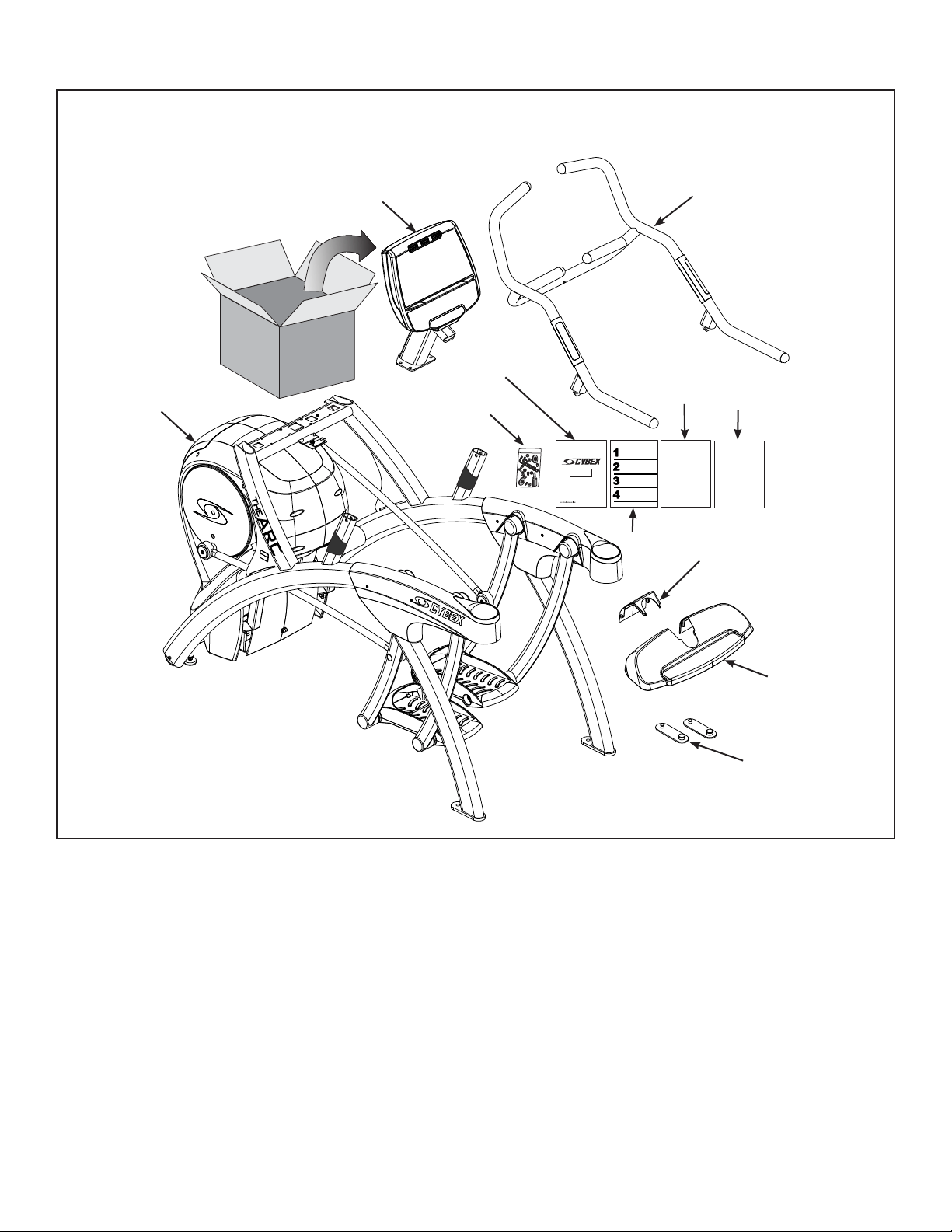
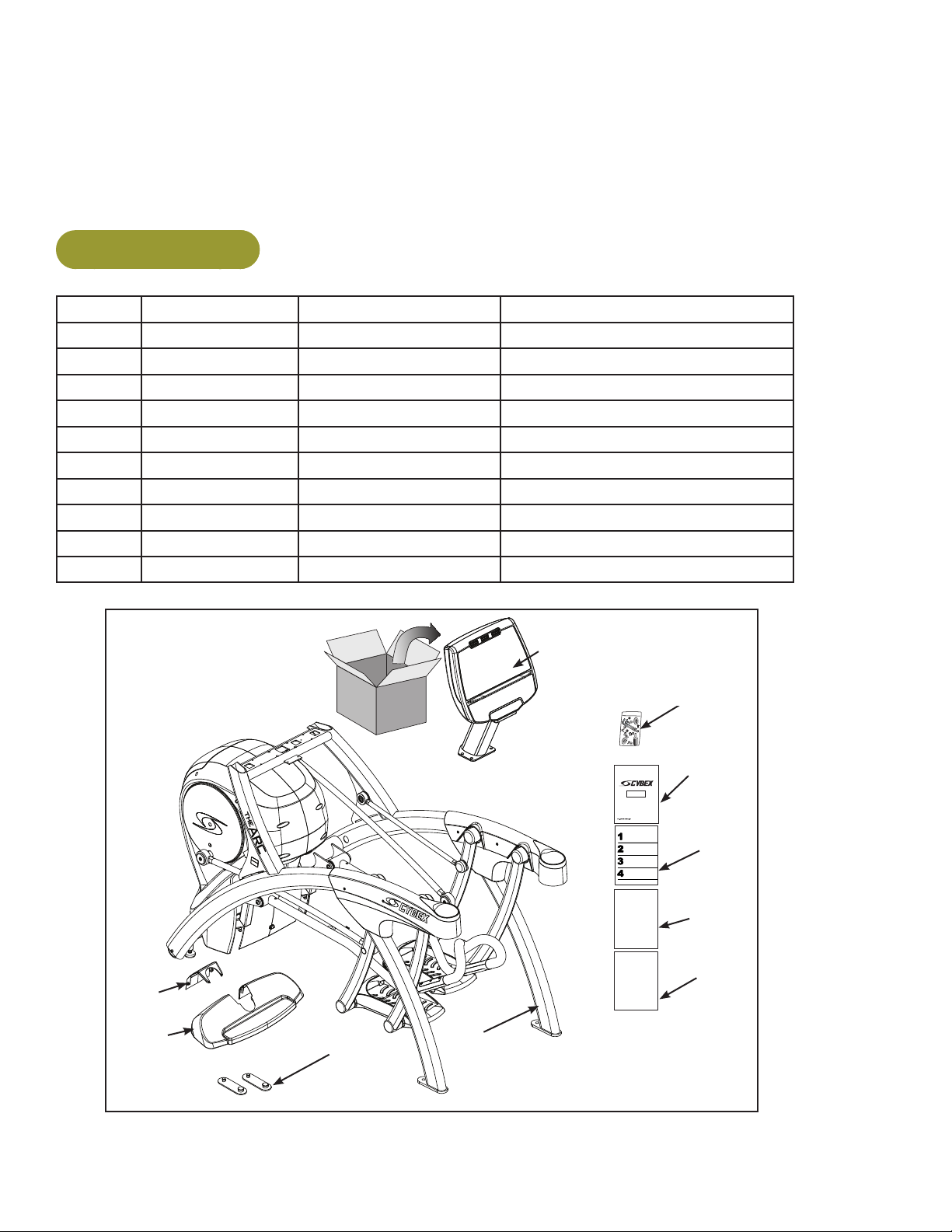
Unpackandverify750Acontentsofcarton.
See 750A content listing and diagram below for 750A carton contents.1.
Check off each item as found. See 2. Customer Service for contact information if any parts are
missing.
750A Contents
Item Quantity Part Number Description
1 1 Vanes Base with covers attached
1a 1 Vanes Console assembly (in box)
2a 1 750A-124 Handrail assembly
3 2 12090-322 Foot pad
4 1 740A-370 Tray, Main
5 1 740A-371 Tray, insert
6 1 NA Hardware pack
7 1 5750-4 Owner’s Manual
8 1 750A-402 Assembly poster
9 1 750A-391 Commercial Arc warranty sheet
10 1 750A-392 Consumer Arc warranty sheet
Cybex Arc Trainer 750A/750AT Owner’s Manual
16
2a
2b
1
3
4
5
6
7
8
9
10
750A
Verify contents of 750A hardware pack
See 750A hardware pack listings 750A hardware pack contents.1.
Check off each item as found. See Customer Service for contact information if any parts are2.
missing.
Cybex Arc Trainer 750A/750AT Owner’s Manual
17
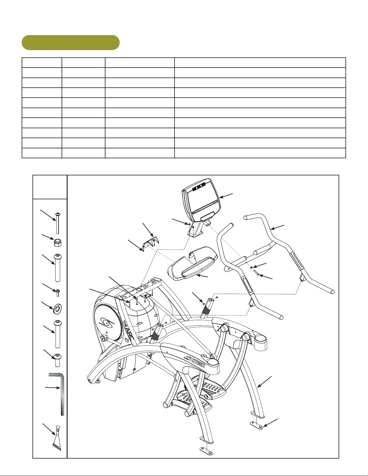
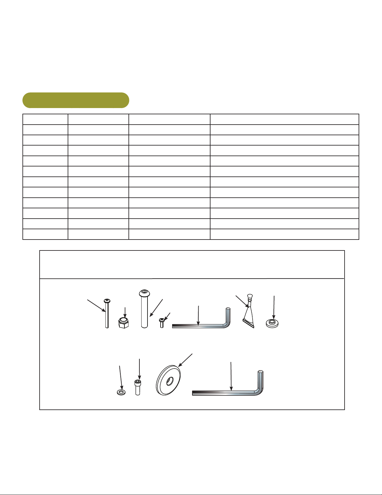
750A Hardware Pack
Item Quantity Part Number Description
11 4 HT592526 Tap SC 10-12 x 2.00 Type A PN HD PHIL
12 4 HN704901 Locknut, .375-16 Nylon
13 5 HC700428 BHSCS .375-16 x 2.25
14a 2 HT552512 Pan HD Phil Hd Self Tapping, 8-16 x .50 Type WB
14b 1 750A-403 Washer, Saddle, .390 ID x .750 OD x 6
14c 1 HX700428 BHSCS .375-16 x 2.25 SS
14d 4 HX700412 BHSCS .375-16 x .50 SS
15 1 BK030204 7/32” Allen Wrench
16 1 YA000201 Loctite
750A
Hardware
11
12
13
14a
14b
14c
14d
15
16
12
11
14c
13
14a
14b
14d
1
2a
2b
3
4
5
750A
Cybex Arc Trainer 750A/750AT Owner’s Manual
18
Verifycontentsof750AThardwarepack.
See 750AT content listing and 750AT carton contents.1.
Check off each item as found. See Customer Service for contact information if any parts are 2.
missing.
750AT Contents
Item Quantity Part Number Description
1 1 Varies
Base with covers attached
2a 1 Varies
Console assembly (in box)
3 2 12090-322
Foot pad
4 1 740A-370
Tray, Main
5 1 740A-371
Tray, Insert
6 1 NA
Hardware pack
7 1 5750-4
Owner’s Manual
8 1 750A-393
Assembly poster
9 1 750A-391
Commercial Arc warranty sheet
10 1 750A-392
Consumer Arc warranty sheet
#7
#8
#9
#10
#5
#2a
#3
#4
#1
#6
750AT
Cybex Arc Trainer 750A/750AT Owner’s Manual
19
Verifycontentsof750AThardwarepack.
See 750AT hardware pack listings and 750AT hardware pack contents.1.
Check off each item as found. See Customer Service for contact information if any parts are 2.
missing.
750AT Hardware Pack
Item Quantity Part Number Description
11 4
HT592526 Tap SC 10-12 x 2.00 Type A PN HD PHIL
12 4
HN704901 Locknut, .375-16 Nylon
13 4
HC700428 BHSCS .375-16 x 2.25
14 2
HT552512 Pan HD Phil Hd Self Tapping, 8-16 x .50 Type WB
15 2
BK030204 7/32” Allen Wrench
16 1
YA000201 Loctite
17 2
600A-311 Flange Spacer
18 2
HS307601 Washer, Flat .281 ID x .500 OD x .062 T
19 2
HX622815 SHCS .250-20 UNC-3A SS
20 2
PL-16535 Linkage Rod Cap 2.00 OD
21 1
BK030201 3/16” Allen Wrench
750AT Hardware
#21
#11
#12
#13
#14
#15
#17
#18
#19
#20
#16
Cybex Arc Trainer 750A/750AT Owner’s Manual
20
#2
#4
#14
#5
#12
#11
#13
#19
#18
#20
#17
#1
#3
750AT
Cybex Arc Trainer 750A/750AT Owner’s Manual
21
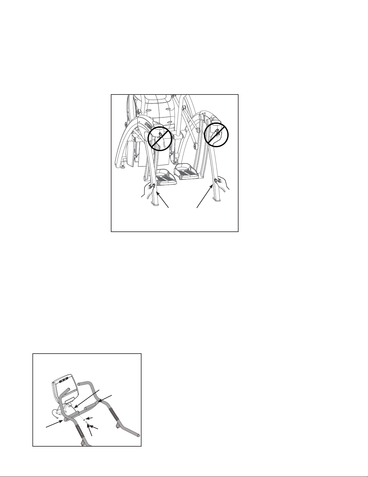
Liftandmoveunit.
1. Carefully remove large bolts and shipping supports. Keep package material on linkage arms at
this time. This will protect the paint from scratching during assembly.
With one person on each side, firmly grasp each rear support leg and lift. Do not grasp plastic 2.
pivot covers. Grasping plastic pivot covers may cause damage to unit.
Lower Rear
Support Legs
Using proper lifting methods, lift the lower rear support legs so the front transport wheels are able 3.
to roll on floor.
Move unit to intended location.4.
Carefully lower rear support leg.5.
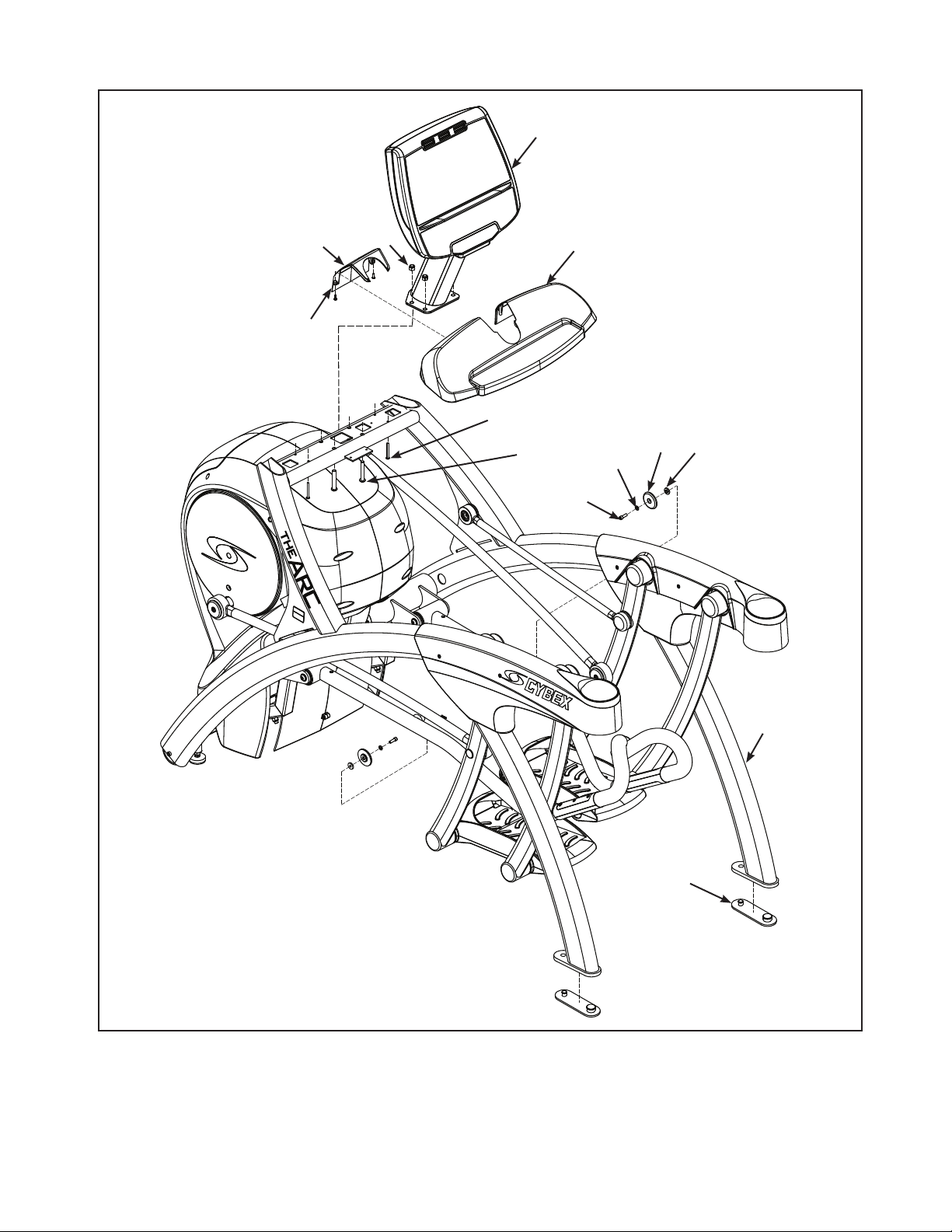
Attach 750A console assembly to handrail assembly.
NOTE: If installing the A/V option, refer to the installation instructions supplied with the A/V unit.
Locate the console assembly (#2a), handrail assembly (#2b), saddle washer (#14a) and one 1.
BHSCS .375-16 x 2.25 SS (#14b).
750A
#2a
#2b
#14a
#14b
Upper Contact
Heart Rate
Cable
#16 (Loctite)
Cybex Arc Trainer 750A/750AT Owner’s Manual
22
Locate the contact heart rate cable in the handrail assembly.2.
Thread upper contact heart rate cable through the console mount.3.
750A
#2a
#2b
#14a
#14b
Upper Contact
Heart Rate
Cable
#16 (Loctite)
Attach 4. the console assembly (#2a) to the handrail assembly (#2b); using a 7/32” Allen wrench,
secure with one saddle washer .390 ID x .750 OD x 6 (#14a) and one BHSCS .375-16 x 2.25 SS
(#14b). Refer to the above diagram.
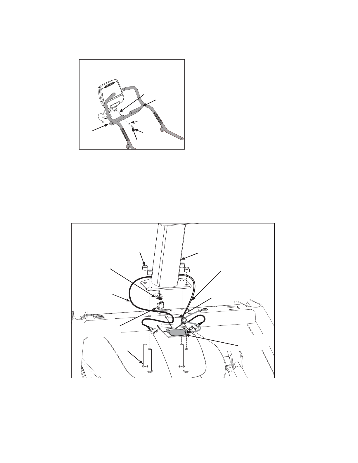
Attach 750A cables
Locate the upper display cable, contact heart rate cable, and plug into the lower display cable.1.
Heart Rate
Display Cable
Upper Display
Cable
Lower Display
Cable
Cable Strap
Contact Heart
Rate Cable
Heart Rate
Board
#12
#13
#2a
750A
Plug the heart rate display cable (threaded through console mount in step 8C) into the heart rate 2.
board. Ensure cable connectors are securely fastened. Tighten cable strap. Refer to above the
diagram.
Cybex Arc Trainer 750A/750AT Owner’s Manual
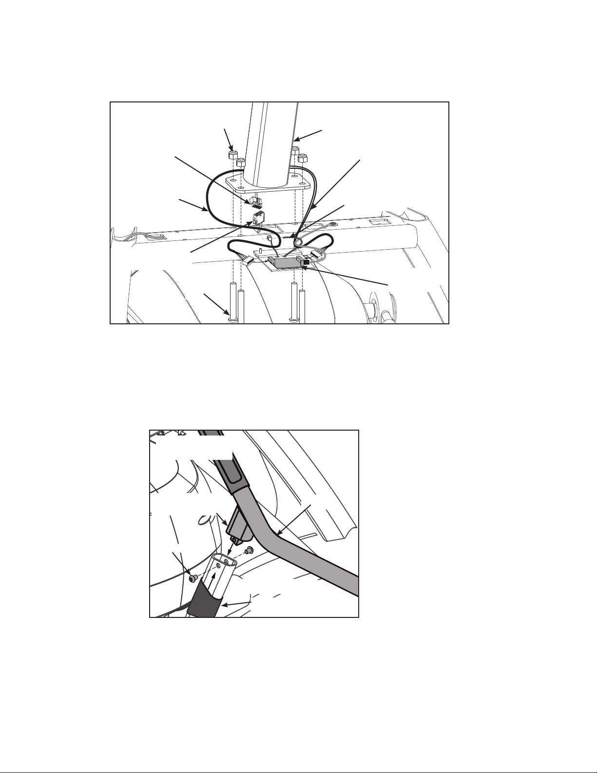
23
Attach750Aconsoleandhandrailassembly.
Locate four nylon locknuts (#12) and four BHSCS .375-16 x 2.25 (#13).1.
Heart Rate
Display Cable
Upper Display
Cable
Lower Display
Cable
Cable Strap
Contact Heart
Rate Cable
Heart Rate
Board
#12
#13
#2a
750A
With an assistant, place the console assembly (#2a) and handrail assembly (#2b) in the correct 2.
position on the main frame. Conrm that no cables are pinched while lowering the console.
Insert (from underneath) the four 3. BHSCS .375-16 x 2.25 (#13). Hand thread the four .375-16 nylon
locknuts (#12) in position. Do not tighten at this point.
Apply loctite4. to and insert the four BHSCS .375-16 x .50 SS (#14d). Do not tighten at this point.
#2b
(both sides)
rubber sleeve
handle-to-frame
connection
#14d
750A
Cybex Arc Trainer 750A/750AT Owner’s Manual
24
Hold the four BHSCS .375-16 x 2.25 (#13) with a 7/32” Allen wrench (#15) while tightening with a 5.
9/16” open end wrench to secure console.
Using a 7/32” Allen wrench, tighten the four BHSCS (#14d) to secure the handle assembly. Refer 6.
to the above diagram.
Pull rubber sleeves up to cover handle-to-frame connections.7.
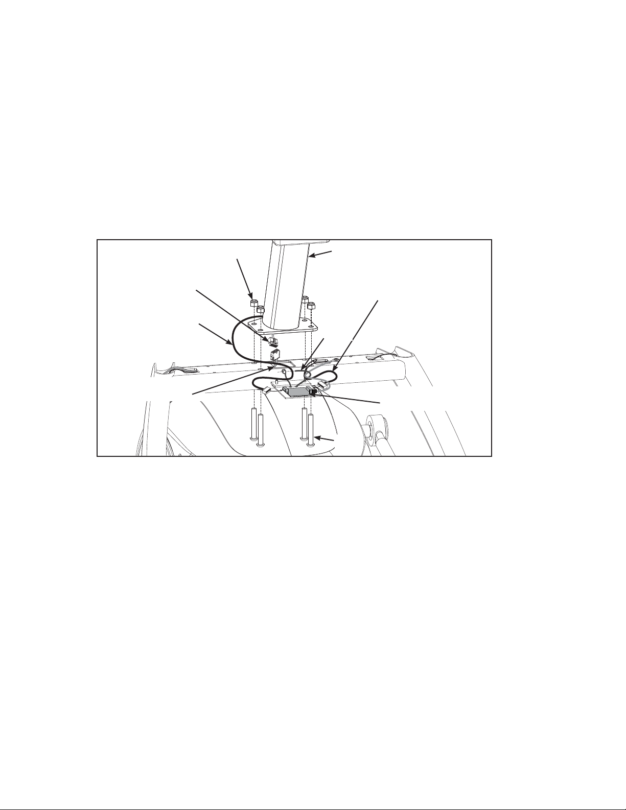
Attach 750AT console assembly.
Locate the console assembly (#2a), four .375-16 nylon locknuts (#12) and four 1. BHSCS
.375-16 x 2.25 (#13).
Heart Rate
Display Cable
Upper Display
Cable
Contact Heart
Rate Cable
Lower Display
Cable
#2a
#13
#12
Cable
Strap
Heart Rate
Board
750AT
Locate the upper display cable and plug into the lower display cable. Refer to the above diagram.2.
Locate the heart rate display cable and plug into heart rate board. Refer to the above diagram.3.
Locate the contact heart rate cable and plug into the heart rate board. Tighten cable strap. Refer 4.
to the above diagram.
Insert (from underneath) the four 5. BHSCS.375-16x2.25(#13). Hand thread the four .375-16 nylon
locknuts (#12) in position. Refer to the above diagram
Conrm that no cables are pinched while lowering the console.6.
Hold the four BHSCS .375-16 x 2.25 (#13) with a 7/32” Allen wrench (#15) while tightening with a 7.
9/16” open-end wrench to secure console. Refer to above diagram.
Cybex Arc Trainer 750A/750AT Owner’s Manual
25
Attach main tray
Locate main tray (#4) and four 1. tap SC 10-12 x 2.00 Type A PN HD PHIL (#11).
Place the main tray (#4) in the correct position on the main frame assembly and hand thread the 2.
four Tap SC 10-12 x 2.00 Type A PN HD PHIL (#11).
#4
#5
#11
#14
Using a Phillips screwdriver, securely fasten the four 3. tapSC10-12x2.00TypeAPNHDPHIL(#11).
Attach tray insert
Locate tray insert (#5) and two 1. Pan HD Phil Hd Self Tapping, 8-16 x .50 Type WB (#14).
Place the insert tray in the correct position on the main frame assembly and hand thread the two 2.
Pan HD Phil Hd Self Tapping, 8-16 x .50 Type WB (#14). Refer to the above diagarm.
Using a Phillips screwdriver, securely fasten the two 3. Pan HD Phil Hd Self Tapping, 8-16 x .50
Type WB (#14).
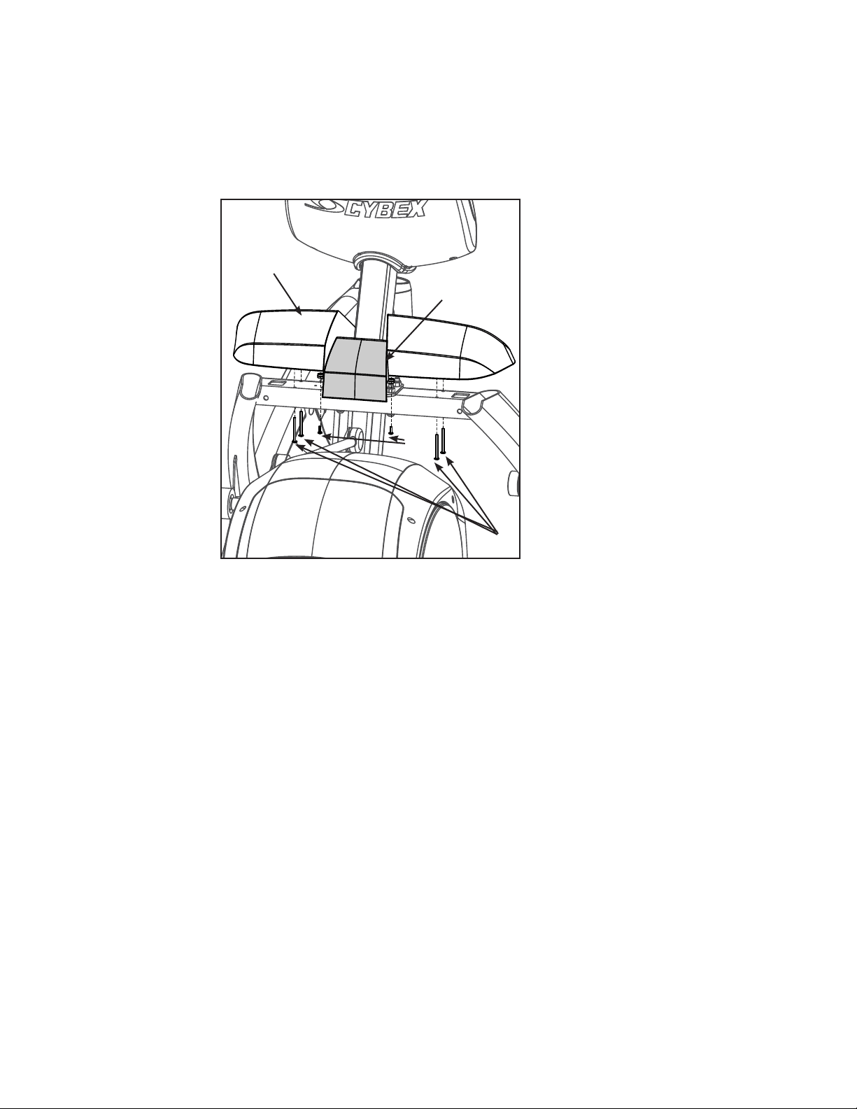
Cybex Arc Trainer 750A/750AT Owner’s Manual
26
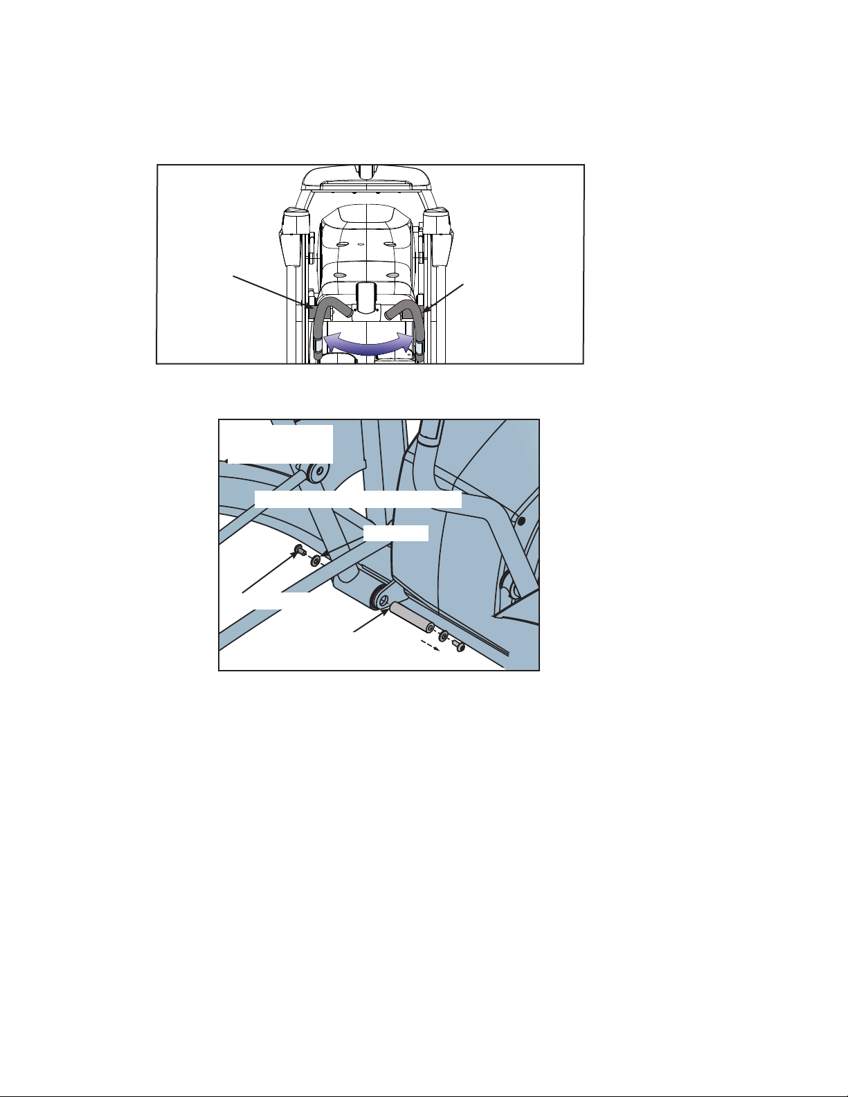
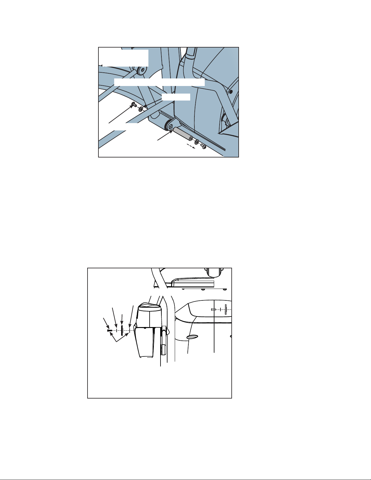
Remove left and right handle assembly
NOTE: The left and right handle assemblies are shipped in the reverse positions. The handle
assemblies must be removed and swapped for proper setup and assembly.
Shipping Position
Right
Handle
Assembly
Left
Handle
Assembly
750AT
Locate the screws and washers that secure each handle assembly to the main frame. 1.
Screw/Loctite
Washer
Pivot Pin
#21
(Both Sides–Left Side Shown)
750AT
Using a 7/32” Allen wrench (#15), remove the screws and washers from the right handle 2.
assembly. Refer to the above diagram.
Verify right handle assembly is mounted on the left side. Refer to diagram at top of page.3.
Cybex Arc Trainer 750A/750AT Owner’s Manual
27
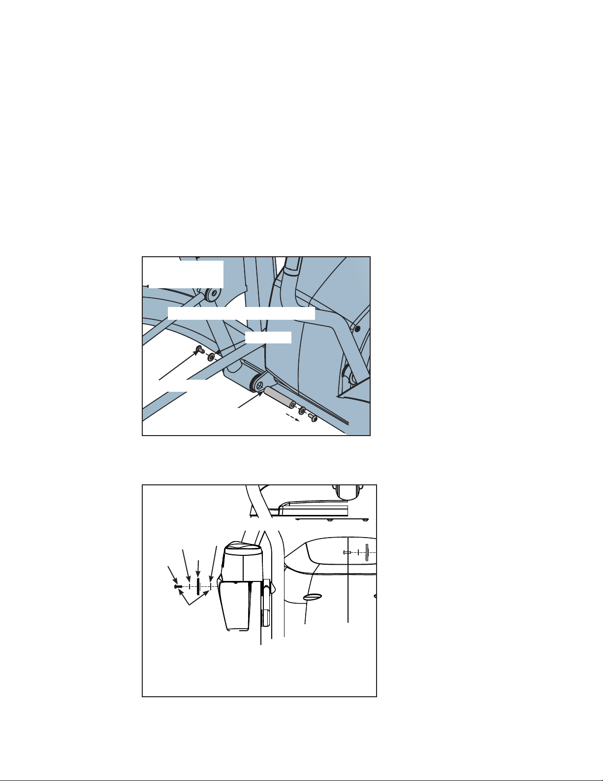
Slide pivot pin out, remove right handle assembly and set aside.4.
Using a 7/32” Allen wrench (#15), remove the screws and washers from the left handle assembly. 5.
Refer to the above diagram.
Verify left handle assembly is mounted on the right side.6.
Slide pivot pin out, remove left handle assembly and set aside.7.
Install the left handle assembly
Position the left handle assembly in the correct position on the left side where the right handle 1.
assembly was removed in step 4 of Remove left and right handle assembly .
Screw/Loctite
Washer
Pivot Pin
#21
(Both Sides–Left Side Shown)
750AT
Apply loctite (#16)2. to threads inside the arm and both screws removed in step 2 of Remove left
and right handle assembly.
(Both Sides–Left Side Shown)
#20
#17
#18
#19
Loctite
(#16)
NOTE: The SHCS .250-20 UNC-3A SS (#19)
must be tightened to a minimum
of 90 in/lbs.
750AT
Cybex Arc Trainer 750A/750AT Owner’s Manual
28
Place left handle assembly in position and slide pivot pin back in place. Refer to diagram under 3.
step one above.
Secure handle assembly with the screws and washers removed in step 2 of 4. Remove left and
right handle assembly . Refer to diagram under step one above.
Locate left linkage rod, left handle assembly, 5. linkage rod cap 2.00 OD (#20), flange spacer (#17),
SHCS .250-20 UNC-3A SS (#19), and flat washer .281 ID x .500 OD x .062 T (#18). Refer to
diagram under step two above.
Place a drop of loctite (#16) on each 6. SHCS .250-20 UNC-3A SS (#19) and another drop inside the
shaft into which the SHCS (#19) will be tightened.
Using a 3/16” Allen wrench (#7), secure linkage rod to handle assembly with 7. linkage rod cap 2.00
OD (#20), flange spacer (#17), SHCS .250-20 UNC-3A SS (#19) and at washer, .281 ID x .500
OD x .062 T (#18).
(Both Sides–Left Side Shown)
#20
#17
#18
#19
Loctite
(#16)
NOTE: The SHCS .250-20 UNC-3A SS (#19)
must be tightened to a minimum
of 90 in/lbs.
750AT
Verify the 8. SHCS .250-20 UNC-3A SS (#19) are tightened to a minimum of 90 in/lbs.
Cybex Arc Trainer 750A/750AT Owner’s Manual
29
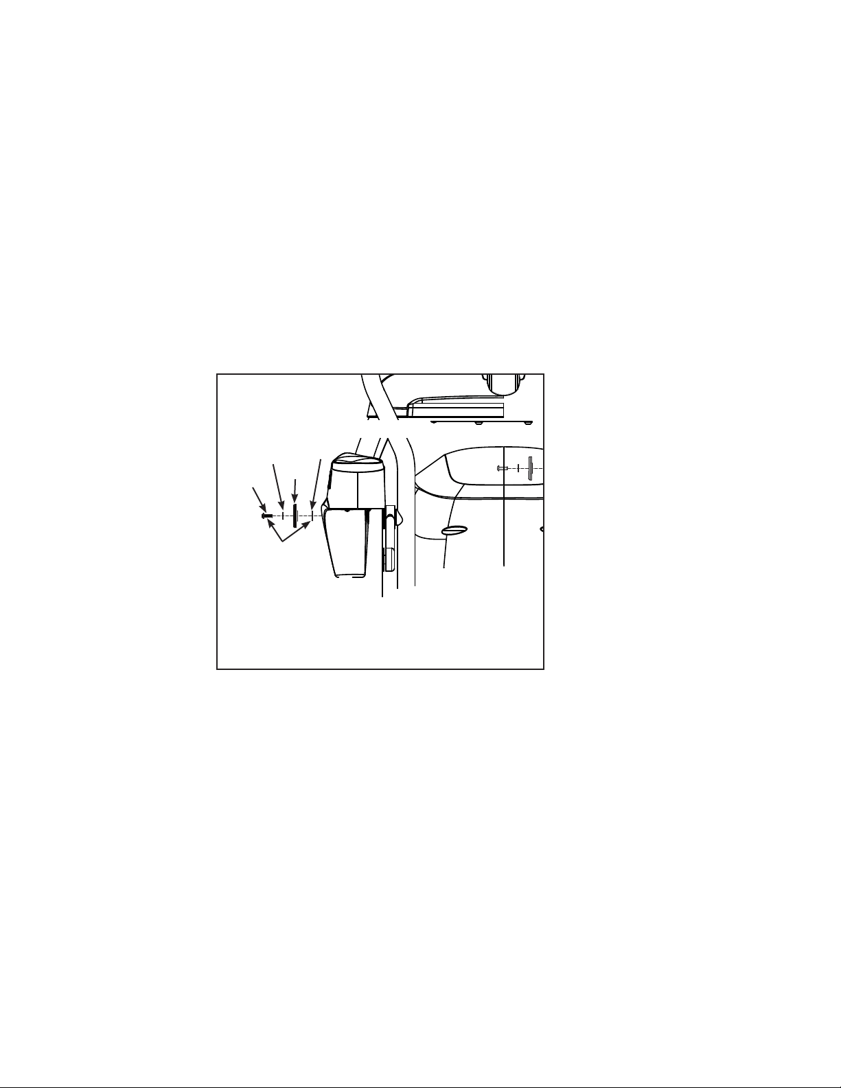
Install right handle assembly
Position the right handle assembly in the correct position on the right side where the left handle 1.
assembly was removed in step 7 of Removeleftandrighthandleassembly.
Screw/Loctite
Washer
Pivot Pin
#21
(Both Sides–Left Side Shown)
750AT
(Both Sides–Left Side Shown)
#20
#17
#18
#19
Loctite
(#16)
NOTE: The SHCS .250-20 UNC-3A SS (#19)
must be tightened to a minimum
of 90 in/lbs.
750AT
Apply loctite (#16)2. to threads inside the arm and screws removed in step two of Remove left and
righthandles.
(Both Sides–Left Side Shown)
#20
#17
#18
#19
Loctite
(#16)
NOTE: The SHCS .250-20 UNC-3A SS (#19)
must be tightened to a minimum
of 90 in/lbs.
750AT
Cybex Arc Trainer 750A/750AT Owner’s Manual
30
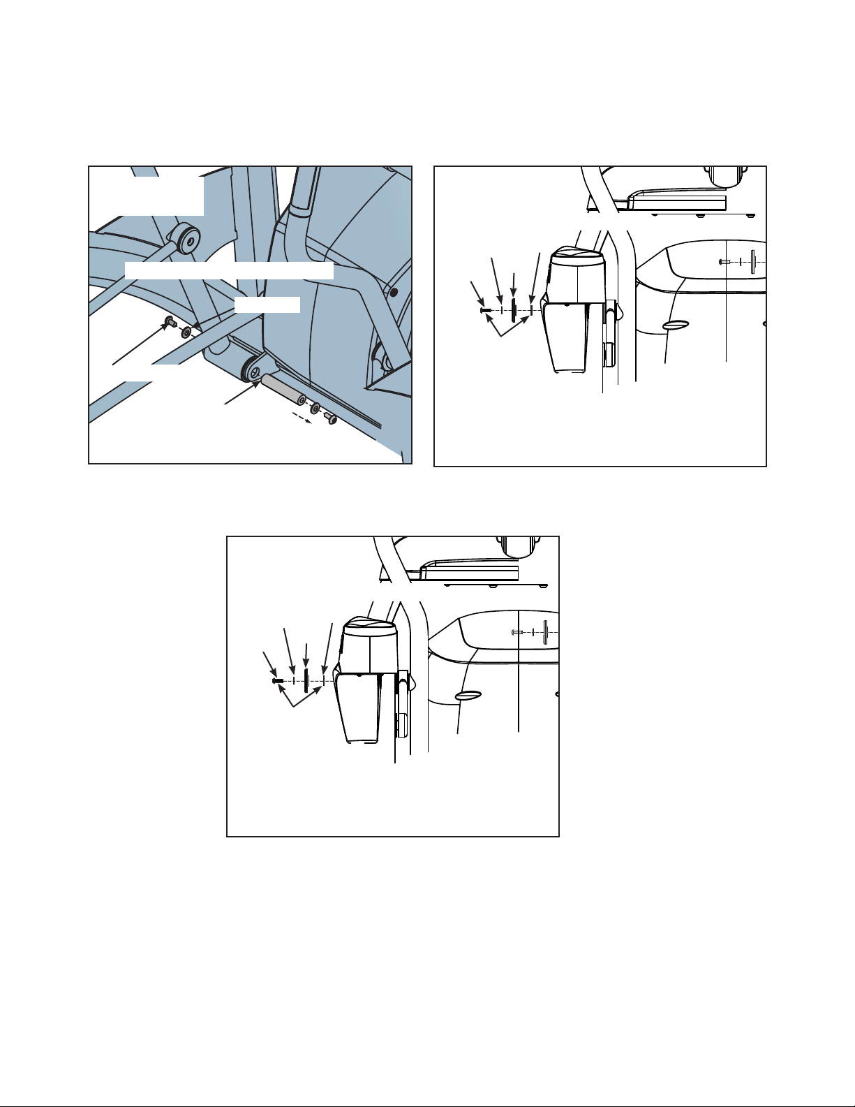
Place right handle assembly in position and slide pivot pin back in place.3.
Screw/Loctite
Washer
Pivot Pin
#21
(Both Sides–Left Side Shown)
750AT
Secure handle assembly with the screws and washers removed in step two of 4. Remove left and
righthandles. Refer to the above diagram.
Locate right linkage rod, right handle assembly, 5. linkage rod cap 2.00 OD (#20), flange spacer
(#17), SHCS .250-20 UNC-3A SS (#19), and flat washer .281 ID x .500 OD x .062 T (#18). Refer
to diagram at top of page.
Place a drop of threadlocker (#21) on each 6. SHCS .250-20 UNC-3A SS (#19) and another drop
inside the shaft into which the SHCS will be tightened.
Secure linkage rod to handle assembly with linkage rod cap7. 2.00OD (#20), flange spacer (#17), SHCS
.250-20UNC-3ASS (#19) and flatwasher.281IDx.500ODx.062T (#18). NOTE: The SHCS.250-20
UNC-3A SS (#19) must be tightened to a minimum of 90 in/lbs.
(Both Sides–Left Side Shown)
#20
#17
#18
#19
Loctite
(#16)
NOTE: The SHCS .250-20 UNC-3A SS (#19)
must be tightened to a minimum
of 90 in/lbs.
750AT
Cybex Arc Trainer 750A/750AT Owner’s Manual
31
Verify handle assemblies are now installed in the correct position.8.
Right
Handle
Assembly
Correct Position
Left
Handle
Assembly
750AT
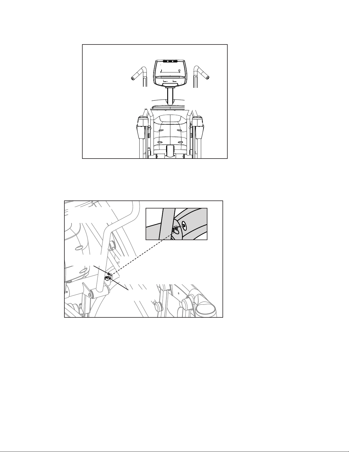
Connect 750AT contact heart rate cable
Locate contact heart rate cable exiting from the right handle assembly.1.
Heart Rate
Wire
Main Frame
Socket
NOTE: Position plug so handle
does not rub cable
during operation.
750AT
Plug right heart rate cable into main frame socket. Refer to the above diagram.2.
Cybex Arc Trainer 750A/750AT Owner’s Manual
32
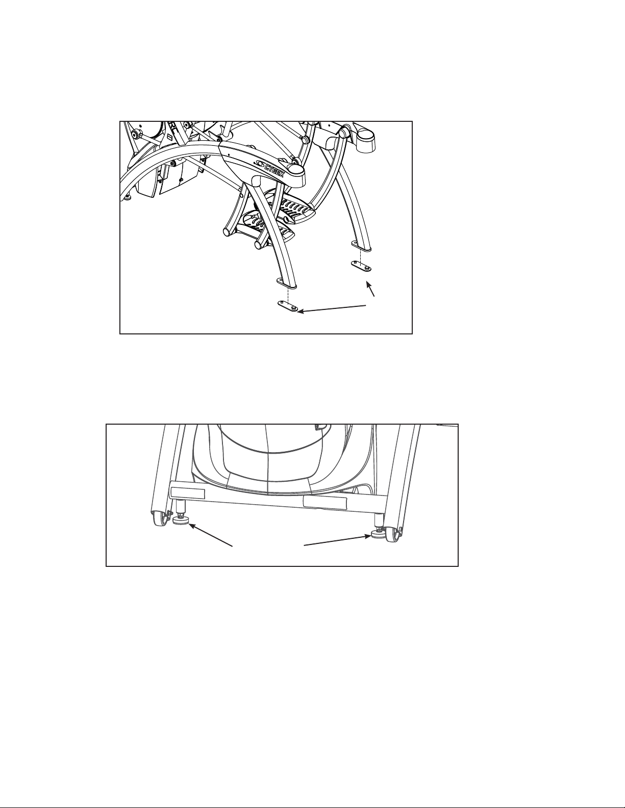
Attach foot pads
Have one person lift the unit while a second person places a foot pad (#3) under each of the two back
feet.
#3
Level unit
Conrm unit is on a level surface. If not, use a 9/16” open-end wrench to adjust the leveling feet up or
down.
Leveling Feet
Visually inspect unit
Carefully remove any package material from arms and rest of unit.1.
Carefully examine the unit to ensure assembly is correct and complete2. .

Cybex Arc Trainer 750A/750AT Owner’s Manual
33
Testing Operation
Use the following instructions to test the full resistance and incline range of the unit:
Plug the optional power cord into a power outlet from a grounded circuit. See 1. Electrical
Requirements in this chapter. NOTE: Coil up the remainder of the power cord and place it out of
the way.
Verify the control panel will illuminate and is in 2. Dormant Mode when using the optional power
adapter.
NOTE: If not using the optional AC power kit, the display will not illuminate until step 4.
Hold the handrails to steady self while stepping into the foot plates.3.
Begin striding.4.
Verify lower heart rate cable is not rubbing on handle during operation.5.
Press the QUICK START key.
Run unit through full resistance range. First press the 6. RESISTANCE + key until unit reaches its
highest load (the display will show “100”). Then press the RESISTANCE - key until unit reaches its
lowest load (the display will show “0”).
NOTE: When unit reaches the set incline and resistance, the displays will stop ashing and remain
steadily illuminated to indicate the desired settings have been reached.
Run unit through full incline range. First press the 7. INCLINE key until the unit reaches its highest
incline (the display will show “20”). Then press the INCLINE key until unit reaches its lowest
incline (the display will show “0”).
WARNING: Wait until all moving parts come to a complete stop before dismounting.
Press PAUSE/END twice to bring the incline back to its start position, end the workout review, and 8.
return the display to Dormant Mode.
Wait until foot plates come to a complete stop before dismounting unit. Hold handrails to steady 9.
self while stepping off unit.

Cybex Arc Trainer 750A/750AT Owner’s Manual
34
Setup Screen
Setup is a separate control screen that allow the user to dene multiple aspects of the unit’s
functions.
Set up can be opened from Dormant mode, Count Down, Lock and the CSAFE ID entry screens.
To open setup screen, press CLEAR, key sequence 7-5-0 and press ENTER.
Press ENTER to enter setup feature, allow changes and return to main menu. PAUSE/END can also
be used to reset and exit to Dormant mode.
Press the RESISTANCE keys to scroll forward or backward in the setup menu.
Press CLEAR to reset back to default or previously stored value.
MENU SET UP Options
1 - Language GERMAN FRENCH
SPANISH ENGLISH
JAPANESE SWEDISH
RUSSIAN
2 - Units ENGLISH (LB/MPH)
METRIC (KG/KPH)
3 - Clock Style 12 HR US DATE 24 HR EURO DATE
12 HR EURO DATE 24 HR US DATE
4 - Current Time 12 HR US DATE ‘HH:MM X MM/DD/YYYY’
24 HR EURO DATE ‘HH:MM DD-MM-YYYY’
12 HR EURO DATE ‘HH:MM X DD-MM-YYYY’
24 HR US DATE ‘HH:MM MM/DD/YYYY’
(Use keypad to enter values or toggle the LOAD
CONTROL key)
5 - Default Time Initial displayed
choice for
programs
requiring a time
setting.
DEFLT TIME 10 DEFLT TIME 60
DEFLT TIME 20 DEFLT TIME 90
DEFLT TIME 30 (default)
NOTE: Choices are limited to range of MAX time.
6 - Review Time Summary of
workout session
totals. Can be
seen as 1, 2 or 3
cycles
SHORT – 1 LONG – 1
SHORT – 2 LONG – 2
SHORT – 3 LONG – 3
7 - Max Time Limit user’s
workout time
MAX TIME = OFF MAX TIME = 50
MAX TIME = 20 MAX TIME = 60 (default)
MAX TIME = 30 MAX TIME = 90
MAX TIME = 40 MAX TIME = 120
MAX TIME = ZONED* (see below)

Cybex Arc Trainer 750A/750AT Owner’s Manual
35
8 - Pause Time Length of time unit
paused during a
workout and still
re-start where
user left off.
PAUSE = OFF (factory setting)
PAUSE = 01:00
PAUSE = 05:00
PAUSE = 10:00
9 - Sound TONE = ON (factory setting)
TONE = OFF
10 - Dormant Style Denes what
is displayed in
Dormant Mode
0 – DEFAULT (default) 3 – CLOCK
1 – TEXT MSG 4 – PROFILES
2 – OUT OF ORDER
11 - Dormant Text** Text is entered via
communications
link.
DORMANT MSG 1
DORMANT MSG 2
DORMANT MSG BOTH
12 - Active Mode
Text on/off**
Text is entered via
communications
link.
WORKOUT MSG ON (or OFF)
13 - Lock
Combination
Requires
correct entry of
combination.
Allows lock
combination to
be enabled and
edited.
Master factory
code is 4300.
Enter on rst set
up.
ENTER OLD CODE (Key in 4-digit code)
CODE _ _ _ _ ON (or OFF)
ENTER will allow code to be seen.
LOAD Control key toggles the lock on or off.
Use keypad to enter new code.
ENTER accepts new code.
14 - Custom
Programs
SAVE
Gives user
capability to
create and store
custom programs
by enabling or
disabling SAVE
button during
Review Mode.
SAVE PROG ON (or OFF). (factory default is OFF)

Cybex Arc Trainer 750A/750AT Owner’s Manual
36
*MAX TIME ZONED If choice is ZONED, choose the actual time for each zone to start and maximum
time setting.
HH:MM X is the actual time the zone starts, and YYY is the maximum time allowed during time zone.
Example:
Format Factory Default
ZONE1 HH:MM X
YYY
ZONE1 05:01A 60
ZONE2 HH:MM X
YYY
ZONE2 09:01A
OFF
ZONE3 HH:MM X
YYY
ZONE3 04:01P 60
ZONE4 HH:MM X
YYY
ZONE4 09:00P
OFF
** For more information on editing Display and Active Mode text, visit www.cybexintl.com/support/
resources/750

Cybex Arc Trainer 750A/750AT Owner’s Manual
37
Operation
Intended Use
Intended use of this exercise equipment is to aid or improve general physical tness and exercise.
Terms Used
Active Mode – Any time the unit is controlling resistance and accumulating workout data. Active
Mode begins after hitting QUICK START during the initial count-down screen, after
completing the setup for a program, or by default if the initial count-down screen times
out and enters QuickStart Manual mode.
Auto-Scan – Display automatically cycles through workout data.
Cool D own – A reduction of work load for a short duration allows user to gently reduce heart rate.
Cool Down occurs two minutes prior to completion of the program-controlled workout
sessions.
Count Down – The lower left INCLINE display shows a 5-0 count down. At the conclusion of the
count down, unit goes into Active Mode.
Dorma nt Mode – Occurs when unit is plugged in with optional AC adaptor and not in use.
Manua l Mode – The unit defaults to this mode if not in a program. Manual Mode allows the user to
adjust the Resistance (0-100) and Incline (0-20). Time will count up in Quick Start
Manual mode or count down to the chosen session time if desired by entering a
TIME or selecting the MANUAL button and completing the setup.
Pause Mode – Occurs only if the Pause feature is enabled and user selects the PAUSE/END key
from Active Mode.
Progra m Setup Mode – Begins after pressing PROGRAM, ADVANCED or MANUAL key. Upon
entering a program, user is prompted to adjust the appropriate settings.
Quick Start – By default, the unit will end up in Quick Start Manual Mode if the user begins striding
and allows the 5 second count-down to end. Also choose the QUICK START button
to enter into Quick Start Manual Mode, where the user controls the Resistance and
Incline as time counts up.
Worko ut Review – Review of the accumulated workout data will happen at the end of each workout
session.

Cybex Arc Trainer 750A/750AT Owner’s Manual
38
Read and understand all warnings and cautions in the Safety Section and all operation
instructions in this chapter before operating unit.
Mount and Dismount
WARNING: Wait until all moving parts come to a complete stop and foot plates are in
lowest position before mounting or dismounting.
To mount unit safely:
Verify unit is in 1. Dormant Mode and foot plates are completely stopped.
Grasp handrail and step carefully onto foot plates.2.
To dismount unit safely:
Wait until foot plates come to a complete stop.1.
Grasp handrails for support and carefully step off back of unit.2.
Emergency Dismount
If an emergency stop and dismount is required:
Grasp handrails for support.1.
Stop striding.2.
Wait until foot plates come to a complete stop.3.
Continue to hold handrails while carefully stepping off unit.4.
Cybex Arc Trainer 750A/750AT Owner’s Manual
39
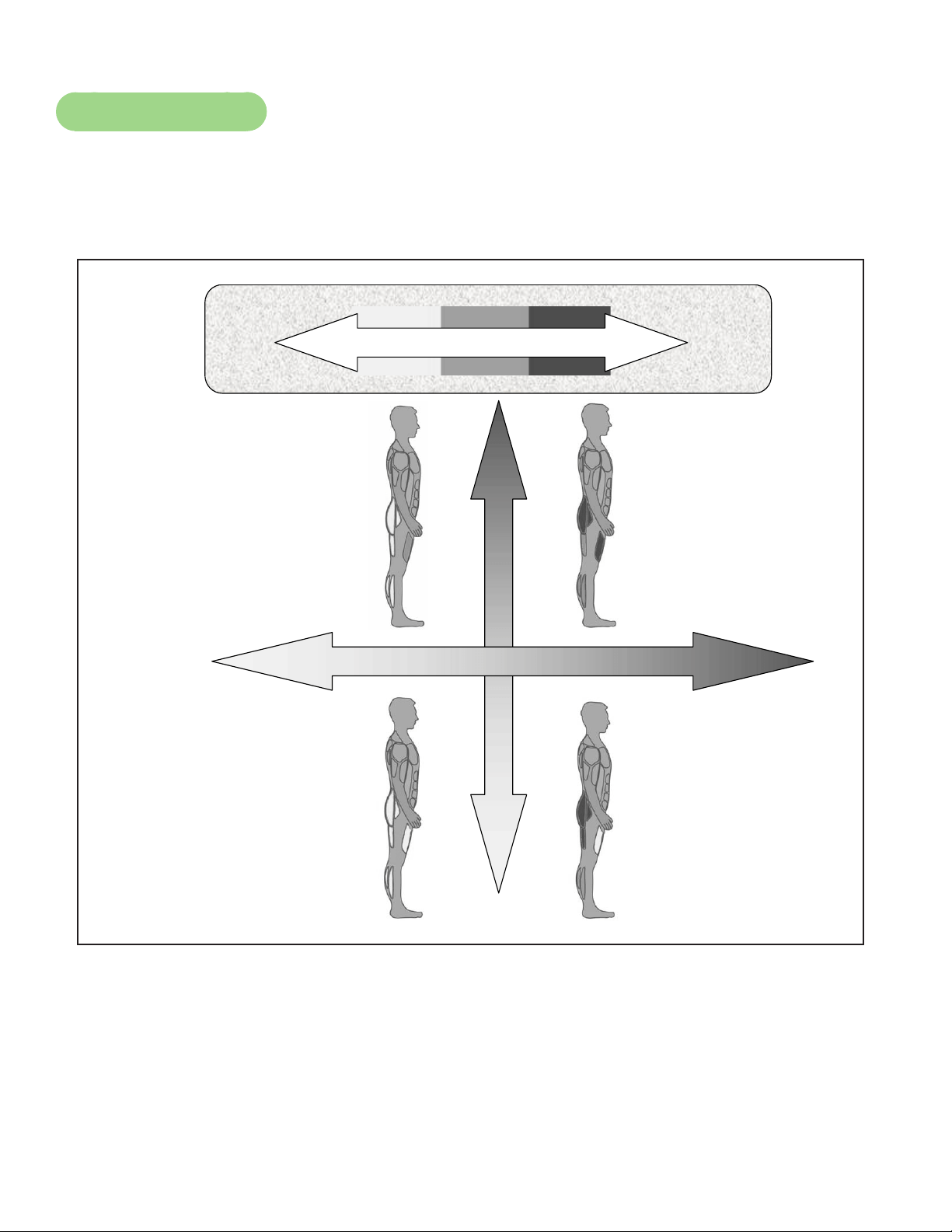
Range of Motion
The elevation is adjustable up or down in the shape of an arc. The lowest setting of 0 equates to
an arc of 12 degrees, where the highest setting of 20 equates to an arc of 34.5 degrees.There is no
difference in muscles used between different incline positions. Differences exist in the intensity of
muscle activity.
Incline
Resistance
Intensity
High
Low
High
HighLow
Low
Cybex Arc Trainer 750A/750AT Owner’s Manual
40
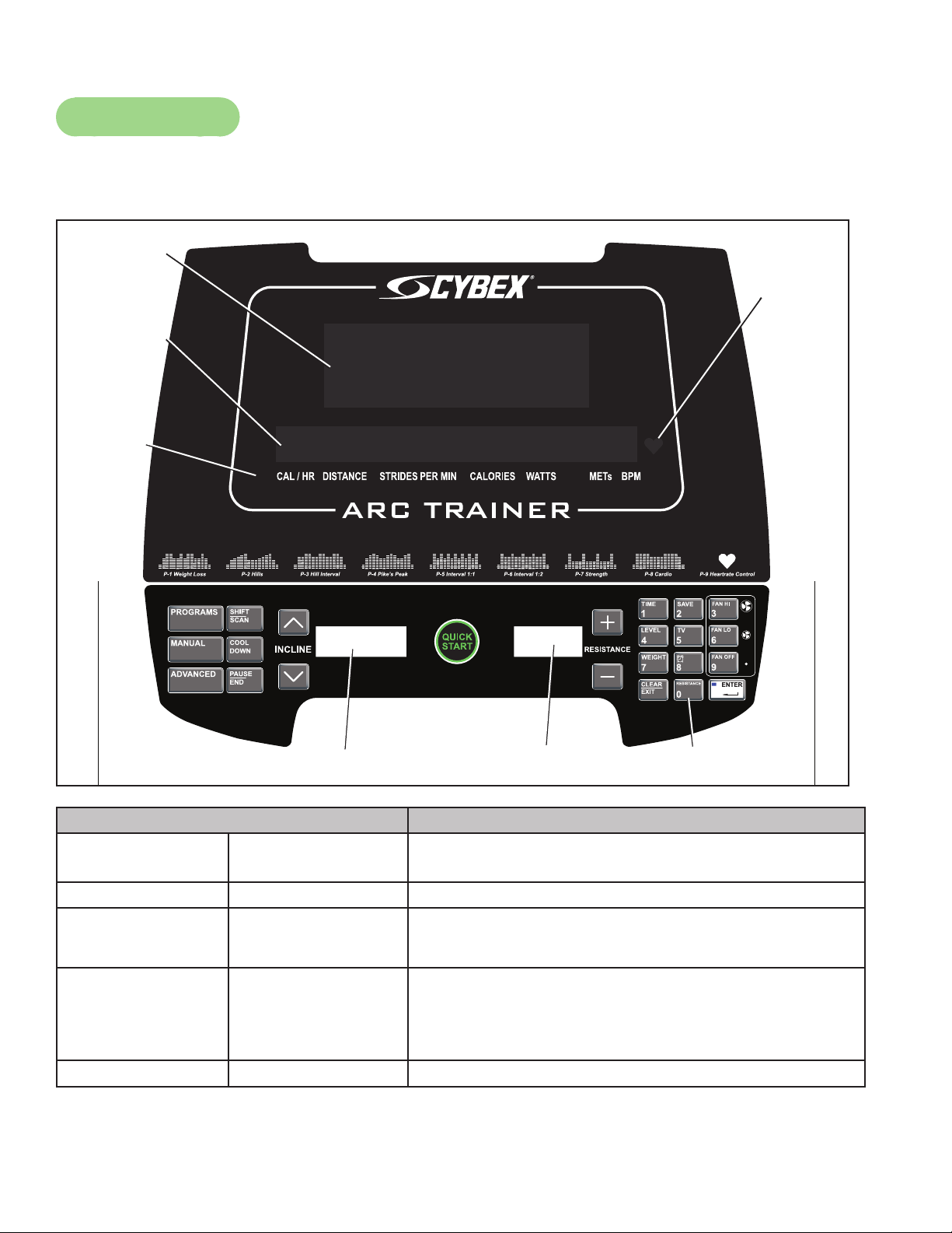
Console Keys
Control keys on the display are usable during operation and may be pressed at any time to make
adjustments in resistance, incline, data readouts or fan speed.
DE-20929-4
C
B Garber
DECAL, 750A, TOP,
ENGLISH
7/7/08
125
1:1
OWATONNA
MFG. APPR.
TECH. PUBS. APPR. D A T E
D A T E
REV.
DWG. NO.
SCALE
SIZE
CHECKED BY
DWG. BY
TITLE:
FINISH:
MATERIAL:
B
SHEET
OF
EXCEPT AS NOTED
GENERAL
TOLERANCES:
2 DECIMALS ± .03
3 DECIMALS ± .015
ANGLES ± 1°
FEATURES SHOWN
PERPENDICULAR OR
PARALLEL SHALL BE
SO WITHIN ± 1°
REMOVE ALL BURRS
BREAK SHARP EDGES
.005/.010 R
SURFACE FINISH
INDICATED PER
ANSI B46.1-1985
GENERAL
MACHINING
DIMENSIONS
IN INCHES
D A T E
D A T E
REMOVE CARBURIZATION
AND SCALE FROM LASER
AND PLASMA CUT EDGES
ALL MATERIAL MUST COMPLY TO
EUROPEAN UNION DIRECTIVE
2002/95/EC RoHS (RESTRICTION
OF HAZARDOUS SUBSTANCES)
1 1
SW-20928-4
REL
REVISIONS
DESCRIPTION
ECOREV
DATE APPROVALBY
THE INFORMATION CONTAINED IN THIS DRAWING IS THE SOLE PROPERTY OF CYBEX.
ANY REPRODUCTION IN PART OR WHOLE WITHOUT
THE WRITTEN PERMISSION OF CYBEX IS PROHIBITED.
.
. ..
.
MEMBRANE, 750A, BOTTOM,
ENGLISH
1 1
Please see SW-20928-X for revision history
6/27/08
_
NOTE:
1. SEE ENGINEERING DRAWING SW-20928-X FOR SPECIFICATIONS.
125
1:1
OWATONNA
MFG. APPR.
TECH. PUBS. APPR. D A T E
D A T E
R E V .
DWG. NO.
SCALE
SIZE
CHECKED BY
DWG. BY
TITLE:
FINISH:
MATERIAL:
B
SHEET
OF
EXCEPT AS NOTED
GENERAL
TOLERANCES:
2 DECIMALS ± .03
3 DECIMALS ± .015
ANGLES ± 1°
FEATURES SHOWN
PERPENDICULAR OR
PARALLEL SHALL BE
SO WITHIN ± 1°
REMOVE ALL BURRS
BREAK SHARP EDGES
.005/.010 R
SURFACE FINISH
INDICATED PER
ANSI B46.1-1985
GENERAL
MACHINING
DIMENSIONS
IN INCHES
D A T E
D A T E
REMOVE CARBURIZATION
AND SCALE FROM LASER
AND PLASMA CUT EDGES
ALL MATERIAL MUST COMPLY TO
EUROPEAN UNION DIRECTIVE
2002/95/EC RoHS (RESTRICTION
OF HAZARDOUS SUBSTANCES)
START
QUICK
ADVANCED
125
1:1
OWATONNA
MFG. APPR.
TECH. PUBS. APPR. DATE
DATE
REV.
DWG. NO.
SCALE
SIZE
CHECKED BY
DWG. BY
TITLE:
FINISH:
MATERIAL:
B
SHEET
OF
EXCEPT AS NOTED
GENERAL
TOLERANCES:
2 DECIMALS ± .03
3 DECIMALS ± .015
ANGLES ± 1°
FEATURES SHOWN
PERPENDICULAR OR
PARALLEL SHALL BE
SO WITHIN ± 1°
REMOVE ALL BURRS
BREAK SHARP EDGES
.005/.010 R
SURFACE FINISH
INDICATED PER
ANSI B46.1-1985
GENERAL
MACHINING
DIMENSIONS
IN INCHES
DATE
DATE
REMOVE CARBURIZATION
AND SCALE FROM LASER
AND PLASMA CUT EDGES
ALL MATERIAL MUST COMPLY TO
EUROPEAN UNION DIRECTIVE
2002/95/EC RoHS (RESTRICTION
OF HAZARDOUS SUBSTANCES)
DE-21240-4
1 1
MASK ENUNCIATOR,
ENGLISH
REL
6-18-08
NOTE:
1. SEE ENGINEERING DRAWING DE-21240-X FOR SPECIFICATIONS.
_
CALORIES
DISTANCE
WATTS
STRIDESCAL / HR PER MIN METs BPM
Heart Rate
Indicator
Bar Graph
Text Area
Data
Readouts
Time/Incline
Resistance
Key Pad
Console Keys Description
PROGRAMS Program Setup
Mode
Choose from nine programs or nine custom programs
MANUAL Manual Mode Go directly to Manual Mode set up
ADVANCED Advanced
Programs
Access Advanced Programs
SHIFT/SCAN Auto-scan Press to disable auto-scan and hold whatever is
being displayed. If auto-scan is on, press to toggle
the data display. If auto-scan is off, hold for three
seconds to reactivate auto-scan.
COOL DOWN Cool Down Mode Initiates the two minute cool-down sequence
Cybex Arc Trainer 750A/750AT Owner’s Manual
41
PAUSE/END Stop Exit Active Mode and go to Pause Mode if enabled.
If Pause Mode is not enabled, work out ends and
Review Mode is entered.
INCLINEΛV Set incline Toggle (Λ V) to increase or decrease incline
QUICK START Quick Start Manual
Mode
Go directly to Quick Start Manual Mode
RESISTANCE + - Adjust resistance Toggle (+ - ) to increase or decrease resistance
Keypad (Program Setup)
TIME Workout time Adjust workout time
LEVEL Workout level Adjust program level (1-10)
WEIGHT User’s Weight When pressed, number keypad is active to allow
keying in body weight
CLEAR/EXIT Multiple uses Reset an entry, back out of a menu, exit the TV’s
EPG mode or reset workout data if in Active Mode
SAVE Save program Save recorded custom workout
TV TV Channel Allows keying in TV channels
ALARM CLOCK Workout alarm
clock
Activate or deactivate workout alarm clock
RESISTANCE Choose resistance Allows direct entry of resistance 0-100
FAN HI High setting Set fan to high setting
FAN LO Low setting Set fan to low setting
FAN OFF Turn fan off Default
ENTER Accept any setting Moves setup process forward
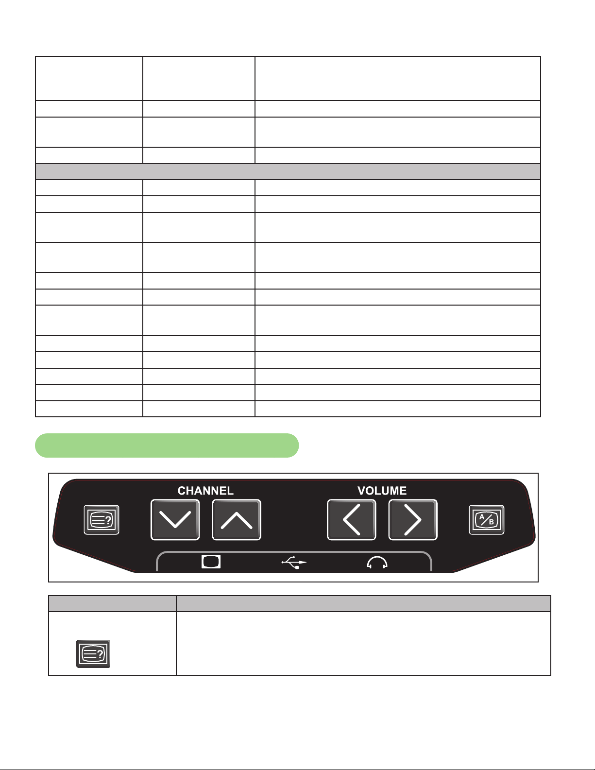
Audio Visual (AV) Key Pad - Optional
Console Key Description
EPG
SW-20813-4
B 5
BGarber
2 OF 2
REVISIONS
DESCRIPTION
ECOREV
DATE APPROVALBY
10 TROTTER DRIVE
MEDWAY, MA
REV.
SHEET
SIZE
APPROVALS
DRAWN BY
MATERIAL
FINISH
ADOBE GENERATED DRAWING
DO NOT MANUALLY UPDATE
CHECKED
RESP ENG
MFG ENG
QUAL ENG
DATE
DWG. NO.
UNLESS OTHERWISE SPECIFIED
DIMENSIONS ARE IN INCHES
TOLERANCES ARE:
FRACTIONS DECIMALS ANGLES
± .XX ± .02 ± 1
.XXX ± .005
FINISH: 125 RMS
SCALE: 1=1 THIS FILE IS IN ADOBE ILLUSTRATOR
DO NOT SCALE DRAWING
THE INFORMATION CONTAINED IN THIS DRAWING IS THE SOLE PROPERTY OF CYBEX.
ANY REPRODUCTION IN PART OR WHOLE WITHOUT
THE WRITTEN PERMISSION OF CYBEX IS PROHIBITED.
.
.
.
. ..
.
.
. . .
.
.
. . .
.
MEMBRANE
A/V CONTROLS,
ENGLISH
5 of 8
Please see Page 1 for revision history
6/20/08
?
B
A
CHANNEL VOLUME
= 70-93
= 94-120
= 121-170
= 171 & UP
Beats Per Minute
HEART RATE ZONE
= 0-69
= 70-93
= 94-120
= 121-170
= 171 EN HOGER
?
B
A
If an Electronic Program Guide (EPG) is available, this will be
displayed on the TV. Use the CHANNEL ΛVand VOLUME < > keys
to navigate in the EPG, ENTER to accept any selections, and CLEAR/
EXIT to exit the EPG mode.
Cybex Arc Trainer 750A/750AT Owner’s Manual
42
CHANNEL
SW-20813-4
B 5
BGarber
2 OF 2
REVISIONS
DESCRIPTION
ECOREV
DATE APPROVALBY
10 TROTTER DRIVE
MEDWAY, MA
REV.
SHEET
SIZE
APPROVALS
DRAWN BY
MATERIAL
FINISH
ADOBE GENERATED DRAWING
DO NOT MANUALLY UPDATE
CHECKED
RESP ENG
MFG ENG
QUAL ENG
DATE
DWG. NO.
UNLESS OTHERWISE SPECIFIED
DIMENSIONS ARE IN INCHES
TOLERANCES ARE:
FRACTIONS DECIMALS ANGLES
± .XX ± .02 ± 1
.XXX ± .005
FINISH: 125 RMS
SCALE: 1=1 THIS FILE IS IN ADOBE ILLUSTRATOR
DO NOT SCALE DRAWING
THE INFORMATION CONTAINED IN THIS DRAWING IS THE SOLE PROPERTY OF CYBEX.
ANY REPRODUCTION IN PART OR WHOLE WITHOUT
THE WRITTEN PERMISSION OF CYBEX IS PROHIBITED.
.
.
.
. ..
.
.
. . .
.
.
. . .
.
MEMBRANE
A/V CONTROLS,
ENGLISH
5 of 8
Please see Page 1 for revision history
6/20/08
?
B
A
CHANNEL VOLUME
= 70-93
= 94-120
= 121-170
= 171 & UP
Beats Per Minute
HEART RATE ZONE
= 0-69
= 70-93
= 94-120
= 121-170
= 171 EN HOGER
?
B
A
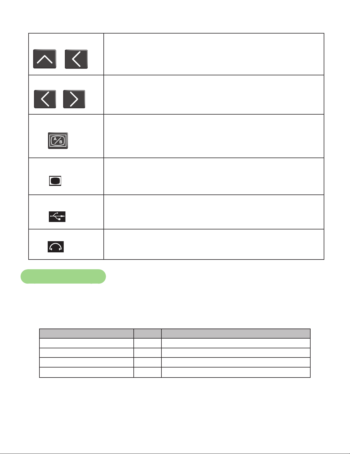
Toggle down or up to change channel (beeping will occur).
VOLUME
SW-20813-4
B 5
BGarber
2 OF 2
REVISIONS
DESCRIPTION
ECOREV
DATE APPROVALBY
10 TROTTER DRIVE
MEDWAY, MA
REV.
SHEET
SIZE
APPROVALS
DRAWN BY
MATERIAL
FINISH
ADOBE GENERATED DRAWING
DO NOT MANUALLY UPDATE
CHECKED
RESP ENG
MFG ENG
QUAL ENG
DATE
DWG. NO.
UNLESS OTHERWISE SPECIFIED
DIMENSIONS ARE IN INCHES
TOLERANCES ARE:
FRACTIONS DECIMALS ANGLES
± .XX ± .02 ± 1
.XXX ± .005
FINISH: 125 RMS
SCALE: 1=1 THIS FILE IS IN ADOBE ILLUSTRATOR
DO NOT SCALE DRAWING
THE INFORMATION CONTAINED IN THIS DRAWING IS THE SOLE PROPERTY OF CYBEX.
ANY REPRODUCTION IN PART OR WHOLE WITHOUT
THE WRITTEN PERMISSION OF CYBEX IS PROHIBITED.
.
.
.
. ..
.
.
. . .
.
.
. . .
.
MEMBRANE
A/V CONTROLS,
ENGLISH
5 of 8
Please see Page 1 for revision history
6/20/08
?
B
A
CHANNEL VOLUME
= 70-93
= 94-120
= 121-170
= 171 & UP
Beats Per Minute
HEART RATE ZONE
= 0-69
= 70-93
= 94-120
= 121-170
= 171 EN HOGER
?
B
A
Press appropriate keys to increase or decrease volume. There is no
display interaction.
VIDEO SOURCE
SW-20813-4
B 5
BGarber
2 OF 2
REVISIONS
DESCRIPTION
ECOREV
DATE APPROVALBY
10 TROTTER DRIVE
MEDWAY, MA
REV.
SHEET
SIZE
APPROVALS
DRAWN BY
MATERIAL
FINISH
ADOBE GENERATED DRAWING
DO NOT MANUALLY UPDATE
CHECKED
RESP ENG
MFG ENG
QUAL ENG
DATE
DWG. NO.
UNLESS OTHERWISE SPECIFIED
DIMENSIONS ARE IN INCHES
TOLERANCES ARE:
FRACTIONS DECIMALS ANGLES
± .XX ± .02 ± 1
.XXX ± .005
FINISH: 125 RMS
SCALE: 1=1 THIS FILE IS IN ADOBE ILLUSTRATOR
DO NOT SCALE DRAWING
THE INFORMATION CONTAINED IN THIS DRAWING IS THE SOLE PROPERTY OF CYBEX.
ANY REPRODUCTION IN PART OR WHOLE WITHOUT
THE WRITTEN PERMISSION OF CYBEX IS PROHIBITED.
.
.
.
. ..
.
.
. . .
.
.
. . .
.
MEMBRANE
A/V CONTROLS,
ENGLISH
5 of 8
Please see Page 1 for revision history
6/20/08
?
B
A
CHANNEL VOLUME
= 70-93
= 94-120
= 121-170
= 171 & UP
Beats Per Minute
HEART RATE ZONE
= 0-69
= 70-93
= 94-120
= 121-170
= 171 EN HOGER
?
B
A
Press to toggle between video source A for cable channels and video
source B for external inputs, such as an iPod
®
video.
VIDEO PORT
SW-20813-4
B 5
BGarber
2 OF 2
REVISIONS
DESCRIPTION
ECOREV
DATE APPROVALBY
10 TROTTER DRIVE
MEDWAY, MA
REV.
SHEET
SIZE
APPROVALS
DRAWN BY
MATERIAL
FINISH
ADOBE GENERATED DRAWING
DO NOT MANUALLY UPDATE
CHECKED
RESP ENG
MFG ENG
QUAL ENG
DATE
DWG. NO.
UNLESS OTHERWISE SPECIFIED
DIMENSIONS ARE IN INCHES
TOLERANCES ARE:
FRACTIONS DECIMALS ANGLES
± .XX ± .02 ± 1
.XXX ± .005
FINISH: 125 RMS
SCALE: 1=1 THIS FILE IS IN ADOBE ILLUSTRATOR
DO NOT SCALE DRAWING
THE INFORMATION CONTAINED IN THIS DRAWING IS THE SOLE PROPERTY OF CYBEX.
ANY REPRODUCTION IN PART OR WHOLE WITHOUT
THE WRITTEN PERMISSION OF CYBEX IS PROHIBITED.
.
.
.
. ..
.
.
. . .
.
.
. . .
.
MEMBRANE
A/V CONTROLS,
ENGLISH
5 of 8
Please see Page 1 for revision history
6/20/08
?
B
A
CHANNEL VOLUME
= 70-93
= 94-120
= 121-170
= 171 & UP
Beats Per Minute
HEART RATE ZONE
= 0-69
= 70-93
= 94-120
= 121-170
= 171 EN HOGER
?
B
A
Video capable port allows personal entertainment device or other
composite video input.
USB PORT
SW-20813-4
B 5
BGarber
2 OF 2
REVISIONS
DESCRIPTION
ECOREV
DATE APPROVALBY
10 TROTTER DRIVE
MEDWAY, MA
REV.
SHEET
SIZE
APPROVALS
DRAWN BY
MATERIAL
FINISH
ADOBE GENERATED DRAWING
DO NOT MANUALLY UPDATE
CHECKED
RESP ENG
MFG ENG
QUAL ENG
DATE
DWG. NO.
UNLESS OTHERWISE SPECIFIED
DIMENSIONS ARE IN INCHES
TOLERANCES ARE:
FRACTIONS DECIMALS ANGLES
± .XX ± .02 ± 1
.XXX ± .005
FINISH: 125 RMS
SCALE: 1=1 THIS FILE IS IN ADOBE ILLUSTRATOR
DO NOT SCALE DRAWING
THE INFORMATION CONTAINED IN THIS DRAWING IS THE SOLE PROPERTY OF CYBEX.
ANY REPRODUCTION IN PART OR WHOLE WITHOUT
THE WRITTEN PERMISSION OF CYBEX IS PROHIBITED.
.
.
.
. ..
.
.
. . .
.
.
. . .
.
MEMBRANE
A/V CONTROLS,
ENGLISH
5 of 8
Please see Page 1 for revision history
6/20/08
?
B
A
CHANNEL VOLUME
= 70-93
= 94-120
= 121-170
= 171 & UP
Beats Per Minute
HEART RATE ZONE
= 0-69
= 70-93
= 94-120
= 121-170
= 171 EN HOGER
?
B
A
Universal Serial Bus (USB) allows different devices to be connected
using a single standardized interface port for charging only.
HEADPHONE PORT
SW-20813-4
B 5
BGarber
2 OF 2
REVISIONS
DESCRIPTION
ECOREV
DATE APPROVALBY
10 TROTTER DRIVE
MEDWAY, MA
REV.
SHEET
SIZE
APPROVALS
DRAWN BY
MATERIAL
FINISH
ADOBE GENERATED DRAWING
DO NOT MANUALLY UPDATE
CHECKED
RESP ENG
MFG ENG
QUAL ENG
DATE
DWG. NO.
UNLESS OTHERWISE SPECIFIED
DIMENSIONS ARE IN INCHES
TOLERANCES ARE:
FRACTIONS DECIMALS ANGLES
± .XX ± .02 ± 1
.XXX ± .005
FINISH: 125 RMS
SCALE: 1=1 THIS FILE IS IN ADOBE ILLUSTRATOR
DO NOT SCALE DRAWING
THE INFORMATION CONTAINED IN THIS DRAWING IS THE SOLE PROPERTY OF CYBEX.
ANY REPRODUCTION IN PART OR WHOLE WITHOUT
THE WRITTEN PERMISSION OF CYBEX IS PROHIBITED.
.
.
.
. ..
.
.
. . .
.
.
. . .
.
MEMBRANE
A/V CONTROLS,
ENGLISH
5 of 8
Please see Page 1 for revision history
6/20/08
?
B
A
CHANNEL VOLUME
= 70-93
= 94-120
= 121-170
= 171 & UP
Beats Per Minute
HEART RATE ZONE
= 0-69
= 70-93
= 94-120
= 121-170
= 171 EN HOGER
?
B
A
Headphone port allows personal headphones.
Program Selection
There are nine different pre-programmed options from which to choose. Speed is never
predetermined. Change speed by changing stride.
Foracompletedescriptionandproleofeachprogram(P1-P8)SeeProgramOverview.
Program Levels Settings
P1 Weight Loss 10 Select time, level and weight.
P2 Hills 10 Select time, level and weight.
P3 Hill Interval 10 Select time, level and weight.
P4 Pike’s Peak 10 Select time, level and weight.

Cybex Arc Trainer 750A/750AT Owner’s Manual
43
P5 Interval 1:1 10 Select time, level and weight.
P6 Interval 1:2 10 Select time, level and weight.
P7 Strength 10 Select time, level and weight.
P8 Cardio 10 Select time, level and weight.
P9 Heart rate Control (HRC) N/A Select time, age, target heart rate and weight.
Navigation
The keypad is active during program setup to key in time, level and weight values. The RESISTANCE
+ - and INCLINE ΛVkeys are also active to adjust the displayed program value (up or down). Hold
down key to accelerate rate of increments.
Press the ENTER key after each step to accept values entered and to move forward in the setup
process.
The QUICK START key may be pressed at any time during this process to accept all program
defaults. If no activity is performed after a program is selected, the unit will default to the settings of
the current program selected.
Press the CLEAR key at anytime to go back to the start of the program list.
Programs P1 – P9 Setup
Press 1. PROGRAMS key to cycle through program choices. Each press of the key will choose
the next program in the list. The number keypad is active to accept a single-digit (1-9) for direct
program access.
Select desired workout time when Text Area prompts “SET PROGRAM TIME XXX”.2.
Select desired workout level when Text Area prompts “SELECT LEVEL 1-10”3.
For P9 - HRC Program only: 4.
Using the number keypad, key in user’s accurate age when Text Area prompts ‘ENTER YOUR AGE •
TO CALCULATE TARGET HEART RATE”. Valid age range values are
13 - 113.
Adjust target heart rate when Text Area scrolls “75% = XXX BPM” and “TARGET BPM AT •
75% = XXX BPM”.
NOTE: Target heart rate is calculated at 75% of Max, where Max Heart rate is calculated at 220
minus the user’s age. Adjust the Target HR up or down from the default 75% value presented
or accept as is.
Using the number keypad, key in user’s accurate weight when Text Area prompts “ENTER YOUR 5.
WEIGHT”. Valid weight range is 50 - 400 lbs (23-181 kgs).

Cybex Arc Trainer 750A/750AT Owner’s Manual
44
Manual and Quick Start Program Setup
NOTE: The Manual and Quick Start programs have no associated prole or level. Program and Level
selection are not available.
Select MANUAL key and enter desired workout time and user’s accurate weight.
Select QUICK START key to directly enter Active Mode. Program is similar to Manual Program
without the option of a congured session time. Time counts up to Max Time.
Advanced Programs A1 – A2 Setup
Press ADVANCED key to cycle through program choices. Each press of the key will choose the next
program in the list.
Program Settings
A1 Constant Power Select time, power level and weight.
A2 Power Training Select time, level and weight.
A1 – Constant Power Setup
Press 1. ADVANCED programs key.
Scroll to (or key in) #1.2.
Enter desired workout time.3.
Select power level when Text Area scrolls “SELECT POWER 50-900 WATTS”. Valid range of 4.
Watts is 50-900 in increments of ve.
Enter user’s accurate weight.5.
A2 – Power Training Setup
Press 1. ADVANCED programs key.
Scroll to (or key in) #2.2.
Enter desired workout time.3.
Enter desired Level (1-21).4.
Enter user’s accurate weight.5.

Cybex Arc Trainer 750A/750AT Owner’s Manual
45
Custom Programs
A maximum of nine custom programs can be created from any workout session. The unit
automatically records incline and resistance; anticipating storing the workout as a custom program
when completed.
Enable the SAVE function by rst entering Setup mode. To enter Setup mode, key sequence
CLEAR, 7-5-0, ENTER during the initial Count Down mode. Pressing the CLEAR key will halt the
countdown to help facilitate keying in 7-5-0, ENTER in sufcient time.
From the menu, use +/- keys to navigate to menu item SAVE PROGRAM and press ENTER to allow
editing the feature.
NOTE: If unit is equipped with an optional power supply, Set Up mode can also be entered during the
Dormant mode.
See Assembly and Set Up for more information on Set Up mode.
To save custom program
During 1. Review Mode, press the SAVE key within the rst ve seconds. The text area will display
“SAVE AS PROG 0X”. X represents the next available slot (01-09).
Using the keypad, enter a number (01 to 09). The 2. +/- keys are available to scroll through the nine
custom program slots.
Press 3. ENTER key to accept and store program.
If nine custom programs already exist, no slots are available; the text area will display “REPLACE
PROG 0X name.” The 0X represents the rst custom program in the list. Use the keypad or LEVEL
keys as described above to select program number.
To play back custom program
Press the Programs key and use the key pad to key in 01 – 09, then press ENTER key.
Note that these programs do not prompt the entry of level or time, as these are aspects that were
saved as part of the program itself.
To delete a custom program
Custom programs require a minimum of one minute, anything less than one minute effectively erases
the program location.
Start a workout session (such as Quick Start) and end before one minute has elapsed.1.
During 2. Review Mode, press SAVE and choose the program slot to be deleted.
Press 3. ENTER.

Cybex Arc Trainer 750A/750AT Owner’s Manual
46
Data Readouts
As the user exercises, the unit keeps track of and displays the following data:
125
1:1
OWATONNA
MFG. APPR.
TECH. PUBS. APPR. DATE
DATE
REV.
DWG. NO.
SCALE
SIZE
CHECKED BY
DWG. BY
TITLE:
FINISH:
MATERIAL:
B
SHEET
OF
EXCEPT AS NOTED
GENERAL
TOLERANCES:
2 DECIMALS ± .03
3 DECIMALS ± .015
ANGLES ± 1°
FEATURES SHOWN
PERPENDICULAR OR
PARALLEL SHALL BE
SO WITHIN ± 1°
REMOVE ALL BURRS
BREAK SHARP EDGES
.005/.010 R
SURFACE FINISH
INDICATED PER
ANSI B46.1-1985
GENERAL
MACHINING
DIMENSIONS
IN INCHES
DATE
DATE
REMOVE CARBURIZATION
AND SCALE FROM LASER
AND PLASMA CUT EDGES
ALL MATERIAL MUST COMPLY TO
EUROPEAN UNION DIRECTIVE
2002/95/EC RoHS (RESTRICTION
OF HAZARDOUS SUBSTANCES)
DE-21240-4
1 1
MASK ENUNCIATOR,
ENGLISH
REL
6-18-08
NOTE:
1. SEE ENGINEERING DRAWING DE-21240-X FOR SPECIFICATIONS.
_
CALORIES
DISTANCE
WATTS
STRIDESCAL / HR PER MIN METs BPM
Calories Per Hour (CAL/HR) – Calculation of present workload’s energy exertion in Calories per
Hour.
Distanc e – The total accumulated distance during workout. Depending on the defaults chosen, this
measurement will show in English (miles) or Metric (kilometers). The unit uses a xed 24”
(61 cm) stroke, giving a travel distance of 48” (122 cm) per revolution.
Distance = Strides per Minute x 24” (61 cm) x Time
Strides per Minute – The average number of strides per minute at current speed.
Calories – The total accumulated calories burned during workout.
WATTS – Present workload energy exertion.
Metabo lic Equivalent (METs) – Displayed only if no BPM signal is present. A MET is the metabolic
equivalent of the energy expended by the human body at rest.
Anything over one MET is considered exertion. METs are calculated
by the display and updated every 1 – 1.2 seconds.
METs = Cal/Hr X 2.2 / User Weight
Beats P er Minute (BPM) – User’s current heart rate. Heart rate will appear when a signal is
introduced.
Heart Rate Indicator
SW-20813-4
B 5
BGarber
2 OF 2
REVISIONS
DESCRIPTION
ECOREV
DATE APPROVALBY
10 TROTTER DRIVE
MEDWAY, MA
REV.
SHEET
SIZE
APPROVALS
DRAWN BY
MATERIAL
FINISH
ADOBE GENERATED DRAWING
DO NOT MANUALLY UPDATE
CHECKED
RESP ENG
MFG ENG
QUAL ENG
DATE
DWG. NO.
UNLESS OTHERWISE SPECIFIED
DIMENSIONS ARE IN INCHES
TOLERANCES ARE:
FRACTIONS DECIMALS ANGLES
± .XX ± .02 ± 1
.XXX ± .005
FINISH: 125 RMS
SCALE: 1=1 THIS FILE IS IN ADOBE ILLUSTRATOR
DO NOT SCALE DRAWING
THE INFORMATION CONTAINED IN THIS DRAWING IS THE SOLE PROPERTY OF CYBEX.
ANY REPRODUCTION IN PART OR WHOLE WITHOUT
THE WRITTEN PERMISSION OF CYBEX IS PROHIBITED.
.
.
.
. ..
.
.
. . .
.
.
. . .
.
MEMBRANE
A/V CONTROLS,
ENGLISH
5 of 8
Please see Page 1 for revision history
6/20/08
?
B
A
CHANNEL VOLUME
= 70-93
= 94-120
= 121-170
= 171 & UP
Beats Per Minute
HEART RATE ZONE
= 0-69
= 70-93
= 94-120
= 121-170
= 171 EN HOGER
?
B
A
Contact Heart Rate – Lightly hold hand grips on the handlebar ensuring that hands are clean and
contact both the front and back sensors of each grip. A heart rate will display in typically 30 seconds
or less.
Factors that interfere with heart rate signal:
hand lotions•
oils or body powder•
excessive dirt•
excessive movement•
body composition•

Cybex Arc Trainer 750A/750AT Owner’s Manual
47
hydration•
too loose grip•
too tight grip•
resting or leaning on grips•
Wireless Display – To use this feature, a Polar® compatible heart rate transmitter belt (not included)
must be worn.
DE-21243-4
B 2
BGarber
2 OF 2
REVISIONS
DESCRIPTION
ECOREV
DATE APPROVALBY
10 TROTTER DRIVE
MEDWAY, MA
REV.
SHEET
SIZE
APPROVALS
DRAWN BY
MATERIAL
FINISH
ADOBE GENERATED DRAWING
DO NOT MANUALLY UPDATE
CHECKED
RESP ENG
MFG ENG
QUAL ENG
DATE
DWG. NO.
UNLESS OTHERWISE SPECIFIED
DIMENSIONS ARE IN INCHES
TOLERANCES ARE:
FRACTIONS DECIMALS ANGLES
± .XX ± .02 ± 1
.XXX ± .005
FINISH: 125 RMS
SCALE: 1=1 THIS FILE IS IN ADOBE ILLUSTRATOR
DO NOT SCALE DRAWING
THE INFORMATION CONTAINED IN THIS DRAWING IS THE SOLE PROPERTY OF CYBEX.
ANY REPRODUCTION IN PART OR WHOLE WITHOUT
THE WRITTEN PERMISSION OF CYBEX IS PROHIBITED.
.
.
.
. ..
.
.
. . .
.
.
. . .
.
DECAL, 750C,
TOP, ENGLISH
3 of 3
Please see Page 1 for revision history
5/16/08
Once the actual heart rate is determined, the LED to the right of the Text Area is blinking
to the displayed BPM and the Heart LED lights up. The color of the light represents a
scale of low to high target heart rate.
White Valid BPM not yet available
Blue 0 – 69 BPM
Green 70 – 93 BPM
Yellow 94 – 119 BPM (Fat Burn Zone)
Blood Orange 120 – 169 (Cardio Zone)
Magenta 170 and higher
Fan Control
The fan defaults at the “OFF” setting. The user can change to “LO” or “HI” setting by pressing the
appropriate control key. NOTE: User must be striding faster than 70 strides per minute for fan to
operate.

Cybex Arc Trainer 750A/750AT Owner’s Manual
48
Alarm Set
To set up an alarm to sound during workout:
Press key #8 on the keypad, also labeled with an alarm clock icon. Text Area will display “ALARM 1.
AT HH:MM Y”. Initially, this display reects actual time.
Use keypad to enter a direct time. Press the ENTER key after each entry to accept and move 2.
forward.
HH (Hour) MM (Minutes) Y=A (AM) or P (PM)
NOTE: The +/- RESISTANCE control keys are also active to scroll the blinking time value up or down.
Hold down key to accelerate rate of increment.
Once alarm is set, the solid blue LED will light on the ENTER key. To cancel the alarm before it
sound, press #8 ALARM key once.
Once alarm time occurs, the display will show “ALARM” and start beeping. Press the CLEAR, ENTER
or #8 ALARM key to reset.
Battery Sentry
Battery Sentry uses display feedback (speed signal, key presses and heart rate) to determine user
presence. If a user is not detected within 20 seconds, the display beeps and inquires “ARE YOU
THERE?”.
Resume striding, grab the contact heart rate grips or press any key within a pre-selected time to
resume workout.

Cybex Arc Trainer 750A/750AT Owner’s Manual
49
Program Overviews
P1 Weight Loss
The Weight Loss program is a ve-minute core program designed for low to medium intensity training
that the user can sustain for an extended period of time. It builds from a low intensity baseline to
include short bursts of higher resistance while the elevation increases by fty percent for two-minutes.
The constant variety provides for periods of higher expenditure and training effect without the
introduction of undue fatigue allowing the user to perform for longer periods of time. See table
Weight Loss
Time
:30 :30 :30 :30 1:00 1:00 1:00 1:00 1:00 :30 :30 :30 :30
Warm Up Program Segments Cool Down
Resistance
1 2 3 4 1 2 3 4 5 1 2 3 4
10 5 10 15 20 25 45 45 25 45 20 15 10 5
9 5 10 15 20 25 40 40 25 40 20 15 10 5
8 5 10 15 20 25 35 35 25 35 20 15 10 5
7 5 5 10 15 25 40 40 25 40 15 10 5 5
6 5 5 10 15 25 35 35 25 35 15 10 5 5
5 5 5 10 15 25 30 30 25 30 15 10 5 5
4 5 5 5 10 15 25 25 15 25 10 5 10 8
3 5 5 5 10 15 20 20 15 20 10 5 10 8
2 5 5 5 5 5 15 15 5 15 5 4 3 3
1 5 5 5 5 5 10 10 5 10 5 4 3 3
Warm Up
Program Segments
Cool Down
Elevation
1 2 3 4 1 2 3 4 5 1 2 3 4
10 8 8 8 8 8 12 12 8 8 8 8 8 8
9 8 8 8 8 8 12 12 8 8 8 8 8 8
8 6 6 6 6 6 12 12 6 6 6 6 6 6
7 6 6 6 6 6 8 8 6 6 6 6 6 6
6 6 6 6 6 6 8 8 6 6 6 6 6 6
5 6 6 6 6 6 8 8 6 6 6 6 6 6
4 4 4 4 4 4 6 6 4 4 4 4 4 4
3 4 4 4 4 4 6 6 4 4 4 4 4 4
2 4 4 4 4 4 6 6 4 4 4 4 4 4
1 4 4 4 4 4 6 6 4 4 4 4 4 4
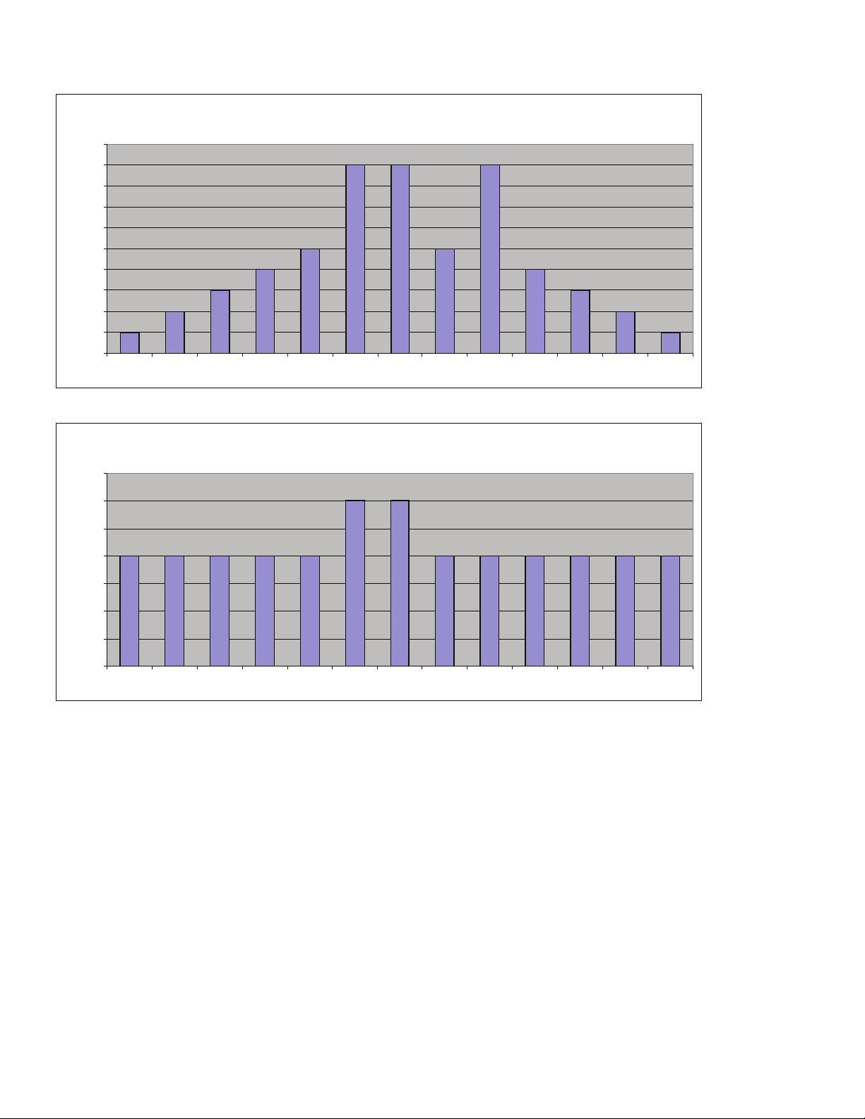
Cybex Arc Trainer 750A/750AT Owner’s Manual
50
Weight Loss
0
5
10
15
20
25
30
35
40
45
50
:30 :30 :30 :30 1:00 1:00 1:00 1:00 1:00 :30 :30 :30 :30
Resistance
Weight Loss
0
2
4
6
8
10
12
14
:30 :30 :30 :30 1:00 1:00 1:00 1:00 1:00 :30 :30 :30 :30
Elevation

Cybex Arc Trainer 750A/750AT Owner’s Manual
51
P2 Hills
The Hills program is a three-minute thirty-second core program designed to give the user an intense
workout. Users will experience moderate resistance and elevation at the beginning to simulate the
start of a climb and will crest at peak elevation gain and difcult resistance after two-minutes. The
resistance then returns to the preliminary level and the core program repeats itself for the next hill.
See table.
Hills
Time
:30 :30 :30 :30 :30 :30 :30 :30 :30 :30 :30 :30 :30 :30 :30
Warm Up Program Segments
Cool Down
Resistance
1 2 3 4 1 2 3 4 5 6 7 1 2 3 4
10 20 30 40 50 50 55 65 75 80 50 50 50 40 30 20
9 20 30 40 45 45 50 60 70 75 45 45 45 40 30 20
8 20 30 35 40 40 45 55 65 75 40 40 40 35 30 20
7 15 25 35 35 35 45 50 60 70 35 35 35 35 25 15
6 15 25 30 35 35 40 50 55 65 35 35 35 30 25 15
5 15 25 30 30 30 35 45 50 60 30 30 30 30 25 15
4 10 20 25 30 25 30 40 50 55 25 25 30 25 20 10
3 10 20 25 25 20 30 40 45 50 20 20 25 25 20 10
2 10 15 20 25 20 25 35 40 45 20 20 25 20 15 10
1 10 10 15 15 20 20 30 35 40 20 20 15 15 10 10
Warm Up
Program Segments Cool Down
Elevation
1 2 3 4 1 2 3 4 5 6 7 1 2 3 4
10 6 8 10 12 16 16 18 20 20 10 10 12 10 8 6
9 6 6 8 10 14 16 16 18 20 10 10 10 8 6 6
8 6 6 8 8 14 14 16 18 18 10 10 8 8 6 6
7 6 6 8 8 12 14 14 16 18 10 10 8 8 6 6
6 6 6 6 8 12 12 14 16 16 10 10 8 6 6 6
5 6 6 6 6 10 12 12 14 16 10 10 6 6 6 6
4 4 4 4 6 10 10 12 14 14 10 10 6 4 4 4
3 4 4 4 6 8 10 10 12 14 10 10 6 4 4 4
2 4 4 4 4 8 8 10 12 12 10 10 4 4 4 4
1 4 4 4 4 6 8 8 10 12 10 10 4 4 4 4
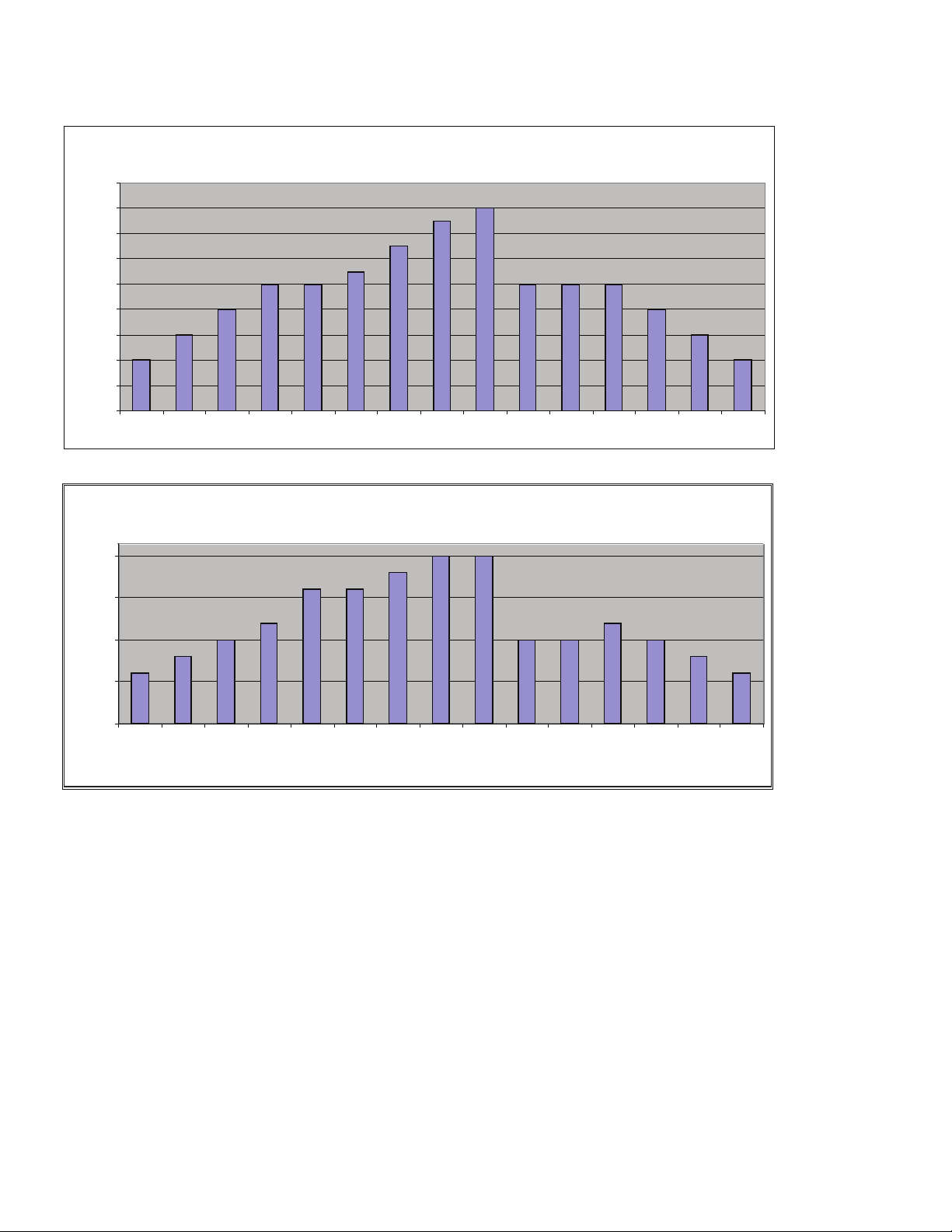
Cybex Arc Trainer 750A/750AT Owner’s Manual
52
Hills
0
10
20
30
40
50
60
70
80
90
:30 :30 :30 :30 :30 :30 :30 :30 :30 :30 :30 :30 :30 :30 :30
Resistance
Hills
0
5
10
15
20
:30 :30 :30 :30 :30 :30 :30 :30 :30 :30 :30 :30 :30 :30 :30
Elevation

Cybex Arc Trainer 750A/750AT Owner’s Manual
53
P3 Hill Interval
The Hills program is a four-minute core program designed for medium intensity workouts. Users will
experience intervals of moderate resistance and elevation at the beginning to simulate the start of a
climb and greater resistance and steeper elevation after two-minutes. The resistance then returns to
the preliminary level and the core program repeats itself for the next interval. See table.
Hill Interval
Time :30 :30 :30 :30 2:00 2:00 :30 :30 :30 :30
Warm Up Cool Down
Warm Up
Cool Down
Program
Segments
Program
Segments
Resistance
1 2 3 4 1 2 1 2 3 4
10 20 25 30 35 40 60 35 30 25 20
9 20 25 30 35 40 50 35 30 25 20
8 15 20 25 30 35 45 30 25 20 15
7 15 20 25 30 35 40 30 25 20 15
6 15 15 20 25 30 35 25 20 15 15
5 15 15 20 25 30 25 25 20 15 15
4 10 10 15 20 25 30 20 15 10 10
3 10 10 15 20 25 25 20 15 10 10
2 10 10 10 15 20 20 15 10 10 10
1 10 10 10 10 15 15 10 10 10 10
Elevation 1 2 3 4 1 2 1 2 3 4
10 6 8 10 12 12 20 12 10 8 6
9 6 6 8 10 10 20 10 8 6 6
8 6 6 8 10 10 18 10 8 6 6
7 6 6 6 8 8 18 8 6 6 6
6 6 6 6 8 8 16 8 6 6 6
5 6 6 6 6 6 16 6 6 6 6
4 6 6 6 6 6 14 6 6 6 6
3 4 4 6 6 6 14 6 6 4 4
2 4 4 6 6 6 12 6 6 4 4
1 4 4 6 6 6 12 6 6 4 4
Program
Segments
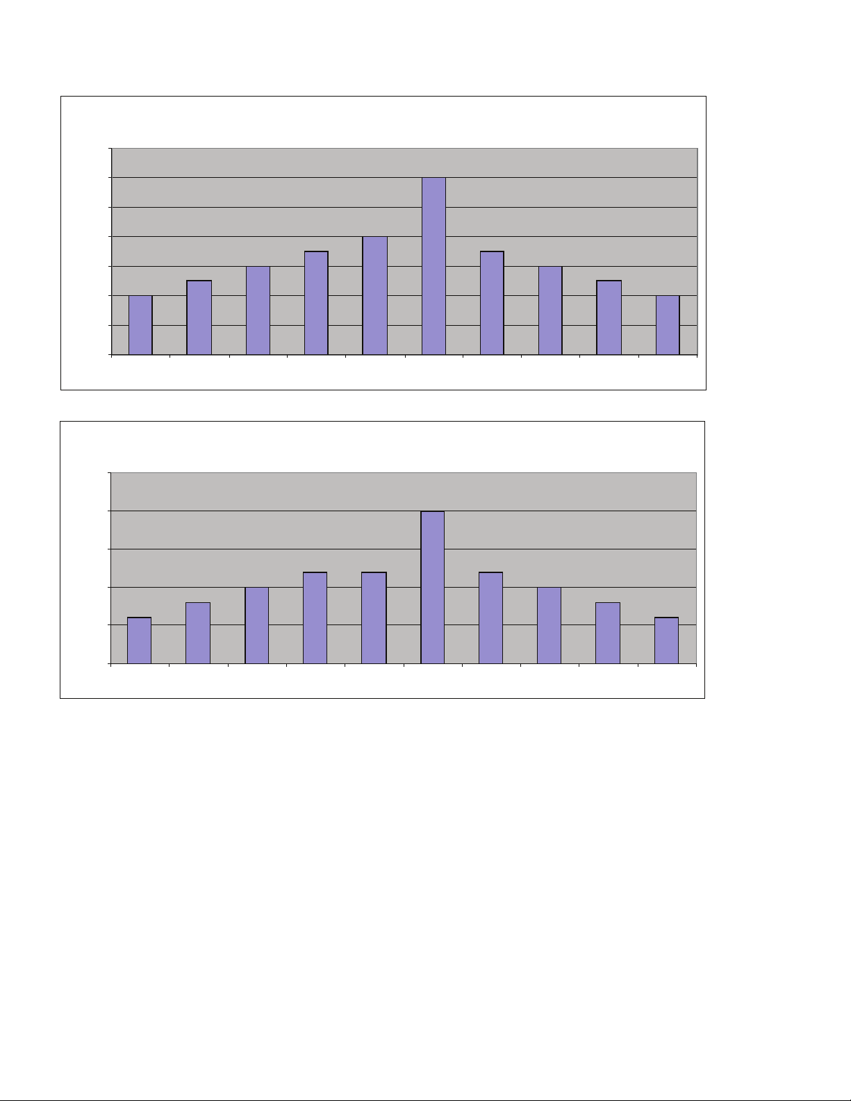
Cybex Arc Trainer 750A/750AT Owner’s Manual
54
Hill Interval
0
10
20
30
40
50
60
70
:30 :30 :30 :30 2:00 2:00 :30 :30 :30 :30
Resistance
Hill Interval
0
5
10
15
20
25
:30 :30 :30 :30 2:00 2:00 :30 :30 :30 :30
Elevation

Cybex Arc Trainer 750A/750AT Owner’s Manual
55
P4 Pikes Peak
Pikes Peak is a ve-minute core program that begins at a low intensity level and incrementally
increases both resistance and elevation until peaking after three-minutes and remains at that level
for one-minute before ramping back down to the initial level. The repetitive program is designed to
encourage a transition in training intensity to encourage the development of aerobic and anaerobic
energy systems.
Pikes Peak
Time
:30 :30 :30 :30 1:00 1:00 1:00 1:00 1:00 :30 :30 :30 :30
Warm Up Program Segments Cool Down
Resistance
1 2 3 4 1 2 3 4 5 1 2 3 4
10 20 25 30 40 50 65 80 65 50 40 30 25 20
9 20 25 30 35 50 60 75 60 50 35 30 25 20
8 20 25 30 35 45 55 70 55 45 35 30 25 20
7 15 20 25 35 45 50 65 50 45 35 25 20 15
6 15 20 25 30 40 45 60 45 40 30 25 20 15
5 10 15 20 20 40 40 55 40 40 20 20 15 10
4 10 10 15 15 30 35 50 35 30 15 15 10 10
3 5 10 10 15 30 30 45 30 30 15 10 10 5
2 5 5 10 10 20 20 40 20 20 10 10 5 5
1 5 5 10 10 15 20 35 20 15 10 10 5 5
Warm Up
Program Segments
Cool Down
Elevation
1 2 3 4 1 2 3 4 5 1 2 3 4
10 6 8 10 10 12 16 20 16 12 10 10 8 6
9 6 8 10 10 11 15 19 15 11 10 10 8 6
8 6 8 8 8 10 14 18 14 10 8 8 8 6
7 6 6 8 8 9 13 17 13 9 8 8 6 6
6 6 6 8 8 8 12 16 12 8 8 8 6 6
5 6 6 8 8 7 11 14 11 7 8 8 6 6
4 6 6 8 8 6 9 12 9 6 8 8 6 6
3 6 6 8 8 5 8 10 8 5 8 8 6 6
2 6 6 8 8 4 6 8 6 4 8 8 6 6
1 6 6 8 8 3 5 6 5 3 8 8 6 6
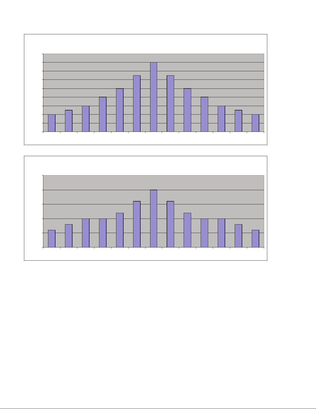
Cybex Arc Trainer 750A/750AT Owner’s Manual
56
Pikes Peak
0
10
20
30
40
50
60
70
80
90
:30 :30 :30 :30 1:00 1:00 1:00 1:00 1:00 :30 :30 :30 :30
Resistance
Pikes Peak
0
5
10
15
20
25
:30 :30 :30 :30 1:00 1:00 1:00 1:00 1:00 :30 :30 :30 :30
Elevation

Cybex Arc Trainer 750A/750AT Owner’s Manual
57
P5 Interval 1:1
The Interval 1:1 program is a two-minute core program utilizing a 1:1 work to rest ratio. It is designed
to improve both aerobic and anaerobic capabilities as users will face a high level of resistance for one
minute followed by a one-minute recuperation period before performing the work interval again. The
elevation remains constant throughout the program. See table.
Warm Up
Warm Up
Program
Segments
Cool Down
Interval 1:1
Warm Up
Cool Down
Program
Segments
Time
:30 :30 :30 :30 1:00 1:00 :30 :30 :30 :30
Resistance
1 2 3 4 1 2 1 2 3 4
10 20 30 35 40 80 50 40 35 30 20
9 15 25 30 35 75 50 35 30 25 15
8 15 20 25 30 75 45 30 25 20 15
7 10 20 25 30 70 45 30 25 20 10
6 10 20 25 30 70 40 30 25 20 10
5 10 15 20 25 65 40 25 20 15 10
4 15 20 20 25 65 35 25 20 20 15
3 10 10 15 20 60 35 20 15 10 10
2 5 10 15 20 60 30 20 15 10 5
1 5 10 15 15 55 30 15 15 10 5
Elevation
1 2 3 4 1 2 1 2 3 4
10 8 8 12 16 20 20 16 12 8 8
9 8 8 12 16 20 20 16 12 8 8
8 8 8 12 12 16 16 12 12 8 8
7 8 8 12 12 16 16 12 12 8 8
6 8 8 12 12 16 16 12 12 8 8
5 8 8 8 12 12 12 12 8 8 8
4 8 8 8 8 12 12 8 8 8 8
3 8 8 8 8 12 12 8 8 8 8
2 8 8 8 8 8 8 8 8 8 8
1 8 8 8 8 8 8 8 8 8 8
Interval 1:1
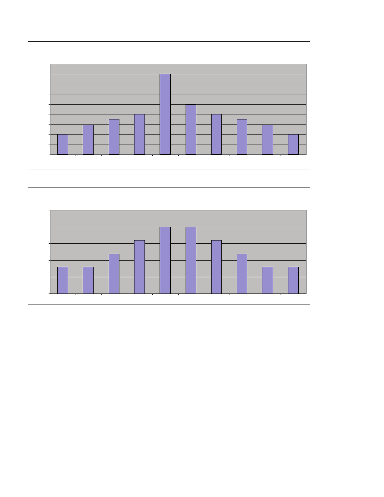
Cybex Arc Trainer 750A/750AT Owner’s Manual
58
Interval 1:1
0
10
20
30
40
50
60
70
80
90
:30 :30 :30 :30 1:00 1:00 :30 :30 :30 :30
Resistance
Interval 1:1
0
5
10
15
20
25
:30 :30 :30 :30 1:00 1:00 :30 :30 :30 :30
Elevation

Cybex Arc Trainer 750A/750AT Owner’s Manual
59
P6 Interval 1:2
The Interval 1:2 program uses a 1:2 work to rest ratio. It is designed for high resistance training with
longer rest periods than the 1:1 program. Users will face a high level of resistance for thirty-seconds
followed by a one minute recuperation period before performing the interval again. The elevation
remains constant throughout the program.
Interval 1:2
Repeat
Time
:30 :30 :30 :30 :30 :30 :30 :30 :30 :30 :30
Warm Up Program Segments Cool Down
Resistance
1 2 3 4 1 2 3 1 2 3 4
10 35 45 55 65 70 45 45 40 35 30 20
9 35 40 50 60 65 40 40 35 30 25 15
8 30 40 50 55 60 35 35 30 25 20 15
7 30 35 45 50 55 30 30 30 25 20 10
6 25 35 40 45 50 30 30 30 25 20 10
5 25 30 35 40 45 25 25 25 20 15 10
4 20 25 30 35 40 25 25 25 20 15 10
3 20 25 30 30 35 20 20 20 15 10 10
2 15 20 25 30 30 20 20 20 15 10 5
1 10 15 20 20 25 15 15 15 15 10 5
Warm Up Program Segments Cool Down
Elevation
1 2 3 4 1 2 3 1 2 3 4
10 8 8 12 16 20 20 20 16 12 8 4
9 8 8 12 16 20 20 20 16 12 8 4
8 8 8 12 12 16 16 16 12 12 8 4
7 8 8 12 12 16 16 16 12 12 8 4
6 8 8 12 12 16 16 16 12 12 8 4
5 8 8 8 12 12 12 12 12 8 8 4
4 8 8 8 8 12 12 12 8 8 8 4
3 8 8 8 8 12 12 12 8 8 8 4
2 8 8 8 8 8 8 8 8 8 8 4
1 8 8 8 8 8 8 8 8 8 8 4
Cybex Arc Trainer 750A/750AT Owner’s Manual
60
Interval 1:2
0
10
20
30
40
50
60
70
80
:30 :30 :30 :30 :30 :30 :30 :30 :30 :30 :30
Resistance
Interval 1:2
0
5
10
15
20
25
:30 :30 :30 :30 :30 :30 :30 :30 :30 :30 :30
Elevation

Cybex Arc Trainer 750A/750AT Owner’s Manual
61
P7 Strength
The Strength program is designed with the specic goal of raising the users’ lactic acid threshold.
The program uses a 1:3 work to rest ratio with fteen-second intervals for maximum power
development and forty-ve second rest periods for recuperation. See table.
Strength
Time
:30 :30 :30 :30 :15 :15 :15 :15 :30 :30 :30 :30
Warm Up
Program Segments Cool Down
Resistance
1 2 3 4 1 2 3 4 1 2 3 4
10 25 30 40 45 100 35 35 35 30 25 20 15
9 25 30 35 40 95 35 35 35 30 25 20 15
8 25 30 35 40 90 35 35 35 30 25 20 15
7 25 30 35 40 85 30 30 30 25 20 20 15
6 20 25 30 35 80 30 30 30 25 20 20 15
5 20 25 30 35 75 30 30 30 25 20 15 10
4 20 25 30 35 70 25 25 25 20 20 0 0
3 20 20 25 30 65 25 25 25 20 20 0 0
2 15 20 25 30 60 20 20 20 15 0 10 5
1 15 15 20 25 55 20 20 20 15 0 10 5
Warm Up Program Segments Cool Down
Elevation
1 2 3 4 1 2 3 4 1 2 3 4
10 10 12 16 18 20 20 20 20 18 16 12 10
9 10 12 16 18 20 20 20 20 18 16 12 10
8 10 12 14 16 18 18 18 18 16 14 12 10
7 10 12 14 16 18 18 18 18 16 14 12 10
6 10 12 14 16 18 18 18 18 16 14 12 10
5 8 10 12 14 16 16 16 16 14 12 10 8
4 8 10 12 14 16 16 16 16 14 12 10 8
3 8 10 12 14 16 16 16 16 14 12 10 8
2 6 8 10 12 14 14 14 14 12 10 8 6
1 6 8 10 12 14 14 14 14 12 10 8 6
Cybex Arc Trainer 750A/750AT Owner’s Manual
62
Strength
0
20
40
60
80
100
120
:30 :30 :30 :30 :15 :15 :15 :15 :30 :30 :30 :30
Resistance
Strength
0
5
10
15
20
25
:30 :30 :30 :30 :15 :15 :15 :15 :30 :30 :30 :30
Elevation

Cybex Arc Trainer 750A/750AT Owner’s Manual
63
P8 Cardio
The Cardio program is designed to maintain a high total demand with two-minutes with high
resistance and low elevation and two minutes at medium resistance with higher elevation for a
total four-minute core program. The prolonged exertion period takes advantage of the long term
energy stores and total aerobic capability when associated with speeds that require a high sustained
cardiovascular demand. See table.
Warm Up
Program
Segments
Cool Down
Warm Up Cool Down
Cardio
Time
:30 :30 :30 :30 2:00 2:00 :30 :30 :30 :30
Resistance
1 2 3 4 1 2 1 2 3 4
10 30 35 45 55 80 60 55 45 35 30
9 25 35 45 55 75 55 55 45 35 25
8 25 30 40 45 70 50 45 40 30 25
7 20 25 35 40 65 45 40 35 25 20
6 15 20 30 35 60 40 35 30 20 15
5 15 20 25 30 55 35 30 25 20 15
4 10 15 20 25 50 30 25 20 15 10
3 5 10 15 20 45 30 20 15 10 5
2 0 5 10 15 40 25 15 10 5 0
1 0 0 5 10 35 20 10 5 0 0
Elevation
1 2 3 4 1 2 1 2 3 4
10 6 8 10 12 10 16 12 10 8 6
9 6 6 8 10 10 16 10 8 6 6
8 6 6 8 8 10 14 8 8 6 6
7 6 6 8 8 8 14 8 8 6 6
6 6 6 6 8 8 12 8 6 6 6
5 6 6 6 6 8 12 6 6 6 6
4 4 4 4 6 6 10 6 4 4 4
3 4 4 4 6 6 10 6 4 4 4
2 4 4 4 4 4 8 4 4 4 4
1 4 4 4 4 4 8 4 4 4 4
Program
Segments
Cybex Arc Trainer 750A/750AT Owner’s Manual
64
Cardio
0
10
20
30
40
50
60
70
80
90
:30 :30 :30 :30 2:00 2:00 :30 :30 :30 :30
Resistance
Cardio
0
2
4
6
8
10
12
14
16
18
:30 :30 :30 :30 2:00 2:00 :30 :30 :30 :30
Elevation

Cybex Arc Trainer 750A/750AT Owner’s Manual
65
Preventive Maintenance
Warnings
Read all warnings in this chapter and in the Safety Section.
Observe the following warnings and cautions:
All maintenance activities shall be performed by qualied personnel. Failure to do so could result in •
serious injury.
To prevent electrical shock, verify unit is unplugged from the electrical outlet before performing any •
cleaning or maintenance procedures. NOTE: A charge can remain after unplugging the power cord.
Keep wet items away from inside parts of unit.•
Performance level of equipment can be maintained only if it is examined regularly for damage and •
wear. NOTE: Pay special attention to components most susceptible to wear.
Replace worn or damaged components immediately and/or keep the equipment out of use until •
repair is completed.
Cleaning Unit
Spray a clean cloth with a mild cleaning agent, such as a water and dish soap solution.1.
Wipe unit.2.
NOTE: Do not spray cleaning solution directly on unit. Direct spraying could cause damage to
electronics and may void warranty.
After Each Use:
Wipe up any liquid spills immediately.•
Wipe up any remaining perspiration from handles and painted surfaces.•
Be careful not to spill or get excessive moisture on the console and display overlays, as this might •
create an electrical hazard or cause failure of the electronics.
Clean heart rate grips using a cloth dampened with a cleaning solution containing alcohol.•
NOTE: The heart rate grips are the only part of the unit where a cleaning solution containing alcohol
should be used.
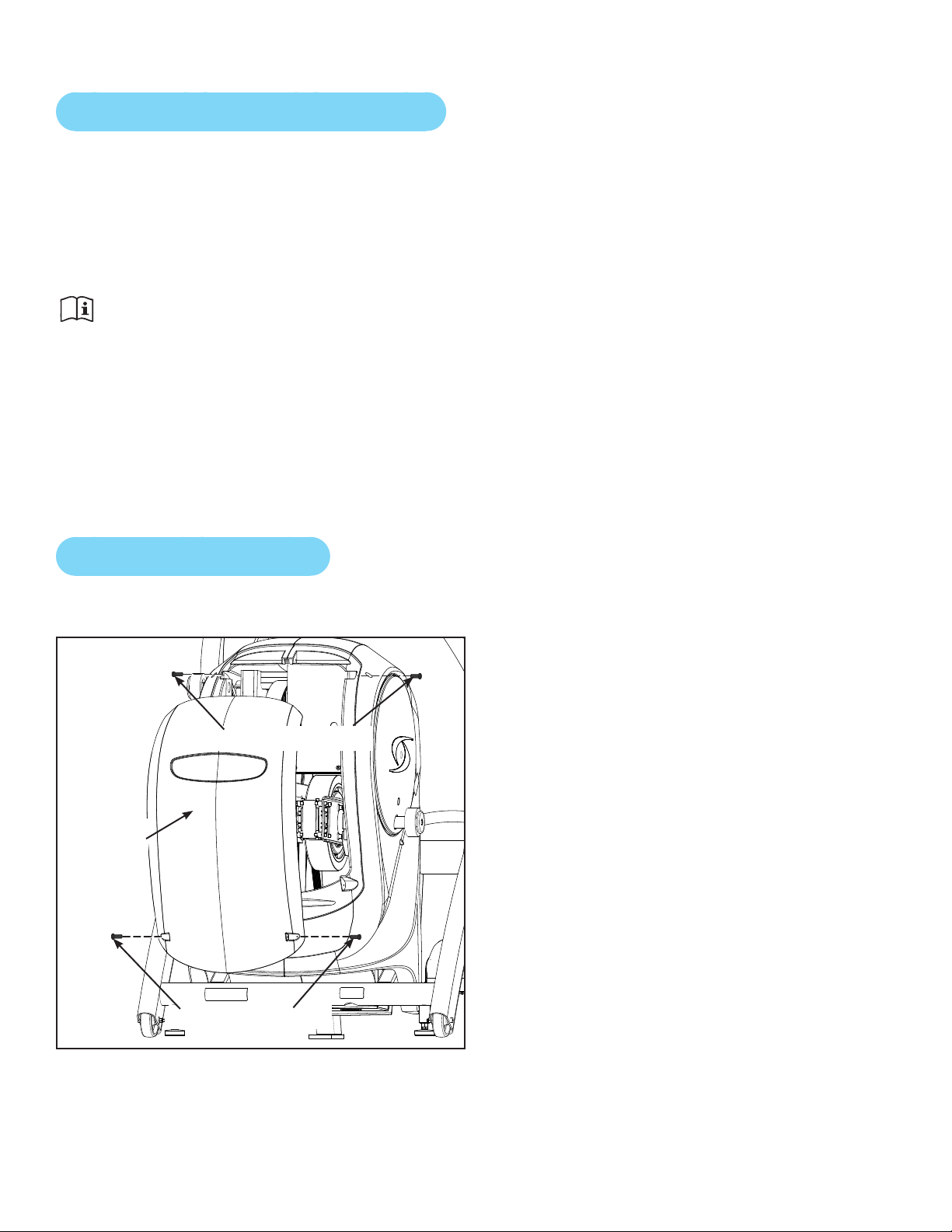
Cybex Arc Trainer 750A/750AT Owner’s Manual
66
Preventive Maintenance Activities
Perform regular preventive maintenance to ensure normal operation of unit. Keep a log of all
maintenance actions to assist in staying current with all preventive maintenance activities.
NOTE: Cybex is not responsible for performing regular inspection and maintenance actions of this
unit. Instruct all personnel in equipment, inspection and maintenance. Require all personnel to
report and record all accidents.
Read and understand warnings listed in this chapter and in the Safety Section. Read and
understand all instructions in this section.
During maintenance, disconnect the external power source. If unit has the optional AC Power Kit,
unplug the power cord from the power outlet.
For some maintenance activities it will be necessary to remove and replace the access cover.
Tool Required
Phillips screwdriver
Remove Access Cover
Using a Phillips screwdriver, remove the two lower screws securing the access cover.1.
Lower Screws (2)
Access
Cover
Upper Screws (2)
Using a Phillips screwdriver, remove two upper screws securing the access cover. Refer to the 2.
above diagram.
Remove the access cover.3.
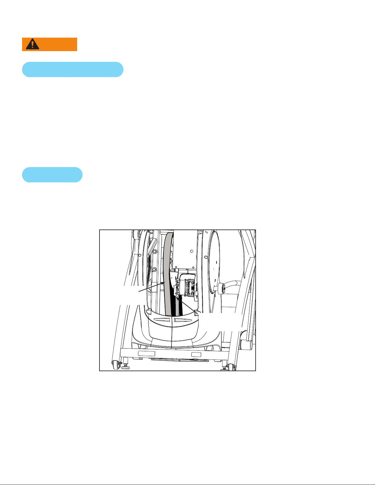
Cybex Arc Trainer 750A/750AT Owner’s Manual
67
WARNING: The ywheel may be hot. Wait until it cools before servicing.
Attach Access Cover
NOTE: Do not over tighten screws.
Using a Phillips screwdriver, replace and tighten the two upper screws removed in step 2 1. Remove
Access Cover.
Using a Phillips screwdriver, replace and tighten the two lower screws removed in step 1 2. Remove
Access Cover.
Test unit for proper operation.3.
Drive Belts
There are two drive belts that may become loose, worn or cracked.
Unless the belts have been removed and not replaced properly, it is unlikely the belts will come loose
or need to be re-tensioned.
Primary
Drive Belt
Secondary
Drive Belt
NOTE: If a belt has cracks or appears worn, it must be replaced immediately by a qualied service
technician.
Primary Belt – The wider of the two belts. It has grooves that keep it aligned on the large upper
pulley.
Secondary Belt – The narrower of the two belts. It has gooves that keep it aligned on the ywheel’s
drive pulley.

Cybex Arc Trainer 750A/750AT Owner’s Manual
68
Recommended Service Schedule
To determine mileage start striding:
During initial countdown, press CLEAR, key in 9-9-9 and pressENTER. The rst menu item is
ODOMETER.
Press ENTER to view accumulated distance.
First 500 Miles (800 KM)
Follow this procedure to ensure the belts are tensioned properly and in good condition.
Remove access cover. (See previous procedure1. Remove Access Cover)
Pull down and roll each belt to examine the condition. If a belt has cracks or appears worn, it must 2.
be replaced immediately by a qualied service technician.
Attach access cover. (See previous procedure3. Attach Access Cover)
Every 5000 Miles (8000 KM)
Check drive belts for tension and wear. (See procedure First 500 Miles)
Move unit and vacuum underneath. Lift the rear of unit and roll it back from its present
position. Vacuum underneath and return unit to normal position.
Clean inside unit.
Remove access cover. (See previous procedure 1. Remove Access Cover)
Using a vacuum cleaner attachment or hand vacuum, clean the exposed components.2.
Remove dirt and debris from internal components.3.
Using a 4. dry cloth, wipe all exposed areas.
Attach access cover. (See procedure5. Attach Access Cover)
Every 20,000 Miles (32000 KM)
Contact qualied service technician to check elevation assembly, replace any worn parts and
lubricate elevation bushings.

Cybex Arc Trainer 750A/750AT Owner’s Manual
69
Statistics
The Statistics screen allows tracking of equipment usage.
Open Statistics screen from Count Down, Lock, CSAFE ID Entry or Dormant Modes
Press Clear, key in 9-9-9 and pressENTER.
Data features can also be accessed from the CSAFE port.
Use the ENTER key to advance to next screen.
Use the RESISTANCE keys to scroll forward or backward in the menu.
Statistics Menu
Display
ST1 –
ODOMETER
KM XXXX.X or
MI XXXX.X
0.0 – 999,999.9 (X=total accumulated miles or KM)
ST2 – HOURS HOURS
XXXXXX
0 – 99999 (X=total user session time)
ST3 – STARTS STARTS
XXXXXX
0 – 999,999 (X=total number of user sessions)
ST4 – MOVES MOVES
XXXXXX
0 – 9,999,999 (X=number of incline moves in 1%
increments)
ST5 – BATTERY BATTERY
XXXXXX
0 – 999,999 (X=total whole minutes the battery has
been used)
ST6 – ERRORS X ERR X HH:MM
M-DD-YY
Tracks error codes in a rolling log of 20 entries, each
stamped with time and date
ST7 – PROGRAM
USAGE
PR Y XXXXXX Y= program number
XXXXX=number of times program was chosen, set
completed and unit entered active mode.
Clear data by holding Pause/End key for three seconds, listen for double beep, and press CLEAR.

Cybex Arc Trainer 750A/750AT Owner’s Manual
70
Error Codes
When an error has occurred, “ERROR #” will appear on the text display alternating with the message
“OUT OF ORDER.”
NOTE: Log number will show in the Incline Display as L-01 through L-20.
Press CLEAR button and hold to clear all errors in log. The display reads “NO ERRORS” when log is
empty.
Press enter to exit out.
NOTE: See contact information in Customer Service for all maintenance and service activities.
Incline and low battery errors are as follows:
Error Number Cause Display Reset/Remedy
24: Incline
moving
too slowly
Incline is commanded to
move, yet the change in
feedback is slower than the
minimum allowed.
None, stored error
only
Inspect and lubricate the •
lead screw.
Re-calibrate the incline.•
Measure the incline •
potentiometer output.
The potentiometer
could be ‘bad’.
Replace the battery. •
25: Incline
movement
feedback
stopped
Incline is commanded to
move yet the feedback
indicates the value is not
changing or ceases to
change as expected.
Dashes shown in
incline window.
Display attempts to
re-calibrate incline
position on entry to
Dormant Mode.
26: Incline
disabled
Incline feedback problems
could not be remedied by
re-calibrating after an Error
25.
Dashes shown in
incline window.
Incline is disabled.
Contact service
technician.
27: Low
Battery
Battery voltage is reported
to be below the limit of
10.7v DC and the controller
has issued the low battery
warning.
Dashes shown in
incline window.
Incline is disabled.
Further use will re-
charge the battery
and the error condition
will be cleared
automatically.

Cybex Arc Trainer 750A/750AT Owner’s Manual
71
Rechargeable Battery
The unit is designed with a 12 volt Lead-Acid rechargeable battery. The battery will recharge during
regular operation of unit or when the optional power adapter is plugged in.
The display will indicate dashes in the incline display if the battery fails to provide enough energy. The
unit will still function normally other than the disabling of the incline feature.
If the battery is completely discharged, the workout review will also be truncated if the user is not
striding during the time period. See Customer Service for contact information to replace the battery
or purchase the optional AC adapter kit.
WARNING: Battery replacement shall be performed by qualied service technician.
Removebatteryanddisposeofsafelybeforeunitdisposal.
Environment
Humidity and Static Electricity
The unit is designed to function normally in an environment with a relative humidity range of 30% to
75%. The unit can be shipped and stored in a relative humidity range of 10% to 90%.
Climatic dry air may cause static electricity. During workout, user may experience a shock due to
build-up of static electricity on the body and the discharge path of the unit. If static electricity is
experienced, increase humidity to a comfortable level through the use of a humidier.
NOTE: Do not install, use or store the unit in an area of high humidity, such as in the vicinity of a
steam room, sauna, indoor pool or outdoors. Exposure to extensive water vapor, chlorine and/
or bromine could adversely affect the electronics as well as other parts of the unit.
Temperature
The unit is designed to function normally in an environment with an ambient temperature range of 50°
F (10° C) to 104° F (40° C). The unit can be shipped and stored in an environment with an ambient
temperature range of 32° F (0° C) to 140° F (60° C).

Cybex Arc Trainer 750A/750AT Owner’s Manual
72
Customer Service
Product Registration
To register product do the following:
Visit 1. www.cybexintl.com.
Locate Product Registration in the Support section.2.
Fill out form completely.3.
Click the Submit button to register product.4.
Contacting Service
Hours of phone service are Monday through Friday from 8:30 a.m. to 6:00 p.m. Eastern Standard
Time.
For Cybex customers living in the USA, contact Cybex Customer Service at 888-462-9239.
For Cybex customers living outside the USA, contact Cybex Customer Service at 508-533-4300 or
fax 508-533-5183.
Find information on the web at www.cybexintl.com or e-mail at [email protected].
The following information located on the serial number decal will assist our Cybex representatives in
serving you.
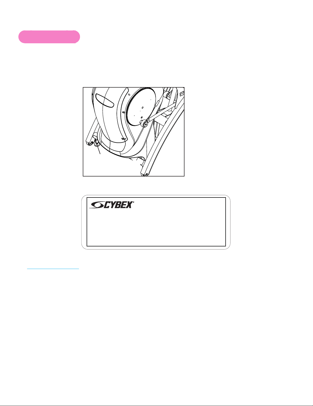
Cybex Arc Trainer 750A/750AT Owner’s Manual
73
Serial Number
The serial number is located on the unit as shown below.
Record serial number below for reference when calling Cybex Customer Service.
Serial Number________________________________
Serial Number location
Unit Serial Number, Product Name and Model Number•
This product may be produced under
one or more of the following patents
5,628,715 5,643,152 5,616,107
5,722,921 5,620,402 6,488,612
6,743,158 7,179,209 7,335,139
7,338,415 7,503,882 D480,773
D481,428 D486,535 D490,127
D490,128 D490,865 D491,237
D491,238 D497,190 6,033,350
7,727,128 7,717,831
1975 24th Ave SW Owatonna,MN. 55060 1-888-462-9239
Made in U.S.A.
MODEL# 8810-90
SERIAL# XXXXXXXXXXXXX
125
1:1
OWATONNA
MFG. APPR.
TECH. PUBS. APPR. DATE
DATE
REV.
DWG. NO.
SCALE
SIZE
CHECKED BY
DWG. BY
TITLE:
FINISH:
MATERIAL:
B
SHEET
OF
1 1
EXCEPT AS NOTED
GENERAL
TOLERANCES:
2 DECIMALS ± .03
3 DECIMALS ± .015
ANGLES ± 1°
FEATURES SHOWN
PERPENDICULAR OR
PARALLEL SHALL BE
SO WITHIN ± 1°
REMOVE ALL BURRS
BREAK SHARP EDGES
.005/.010 R
SURFACE FINISH
INDICATED PER
ANSI B46.1-1985
GENERAL
MACHINING
DIMENSIONS
IN INCHES
DATE
DATE
REMOVE CARBURIZATION
AND SCALE FROM LASER
AND PLASMA CUT EDGES
Serial Number 8800 Decal
REL 2/4/2011
ALL MATERIAL MUST COMPLY TO
EUROPEAN UNION DIRECTIVE
2002/95/EC RoHS (RESTRICTION
OF HAZARDOUS SUBSTANCES)
Part Description and Part Number if you have it. All parts can be found on the web at •
www.cybexintl.com
Shipping Address•
Contact Name•
In addition to your shipping address and contact name, your account number is helpful but not
required. You may also fax orders to 508-533-5183.

Cybex Arc Trainer 750A/750AT Owner’s Manual
74
Ordering Parts
To order parts online go to www.cybexintl.com. Select Support > Parts / Ordering. In the left
navigation panel, click Parts Diagrams - Current Products. Select from the drop down boxes.
To speak with a customer service representative, call 888-462-9239 (for customers living within the
USA) or 508-533-4300 (for customers outside the USA). You may also contact us through e-mail at
Servicing of Double-Insulated Products
In a double-insulated product, two systems of insulation are provided instead of grounding. No
grounding means is provided on a double-insulated product, nor should a means for grounding be
added to the product.
Servicing a double-insulated product requires extreme care and knowledge of the system, and should
be done only by qualied service personnel. Replacement parts for a double-insulated product must
be identical to the parts they replace. A double-insulated product is marked with the words
“DOUBLE INSULATION” or “DOUBLE INSULATED.” The symbol (square within a square) may also
be marked on the product.
Symbol Description
Double-Insulated symbol
BF
Return Material Authorization (RMA)
The Return Material Authorization (RMA) system is used when returning material for placement,
repair or credit. The system assures that returned materials are properly handled and analyzed.
Follow the following procedures carefully.
Contact your authorized Cybex dealer on all warranty-related matters. Your local Cybex dealer will
request a RMA from Cybex, if applicable. Under no circumstances will defective parts or equipment
be accepted by Cybex without proper RMA and an Automated Return Service (ARS) label.
Call the Customer Service Hot Line 888-462-9239 for the return of any item that is defective.

Cybex Arc Trainer 750A/750AT Owner’s Manual
75
Provide the technician with a detailed description of the problem you are having or the defect in the
item you wish to return. Provide the model and serial number of your Cybex equipment.
At Cybex’s discretion, the technician may request that you return the problem part(s) to Cybex for
evaluation and repair or replacement. The technician will assign you a RMA number and will send
you an ARS label. The ARS label and the RMA numbers must be clearly displayed on the outside
of the package that contains the item(s) to be returned. Include the description of the problem, the
serial number of the equipment and the name and address of the owner in the package along with the
part(s).
Forward the package through UPS to Cybex.
Attn: Customer Service Department
Cybex International, Inc.
1975 24th Ave SW
Owatonna, MN 55060
Merchandise returned without an RMA number on the outside of the package or shipments sent COD
will not be accepted by the Cybex receiving department.
Damaged Parts
Materials damaged in shipment should not be returned for credit. Shipping damages are the
responsibility of the carrier (UPS, Federal Express, trucking companies, etc.)
Apparent Damage
Upon receipt of your shipment, check all items carefully. Any damage seen with a visual check must
be noted on the freight bill and signed by the carrier’s agent. Failure to do so will result in the carriers
refusal to honor your damage claim. The carrier will provide you with the required forms for ling such
claims.
Concealed Damage
Damage not seen with a visual check upon receipt of a shipment but notices later must be reported
to the carrier as soon as possible. Upon discovery of the damage, a written or phone request to
the carrier asking them to perform an inspection of the materials must be made within ten days of
the delivery date. Keep all shipping containers and packing materials as they will be needed in the
inspection process. The carrier will provide you with an inspection report and the necessary forms for
ling a concealed damage claim. Concealed damage claim is the carrier’s responsibility.


10 Trotter Drive Medway, MA 02053 • 508-533-4300 • FAX 508-533-5183
www.cybexintl.com • [email protected]